EDIXA - Edixa Reflex Repair
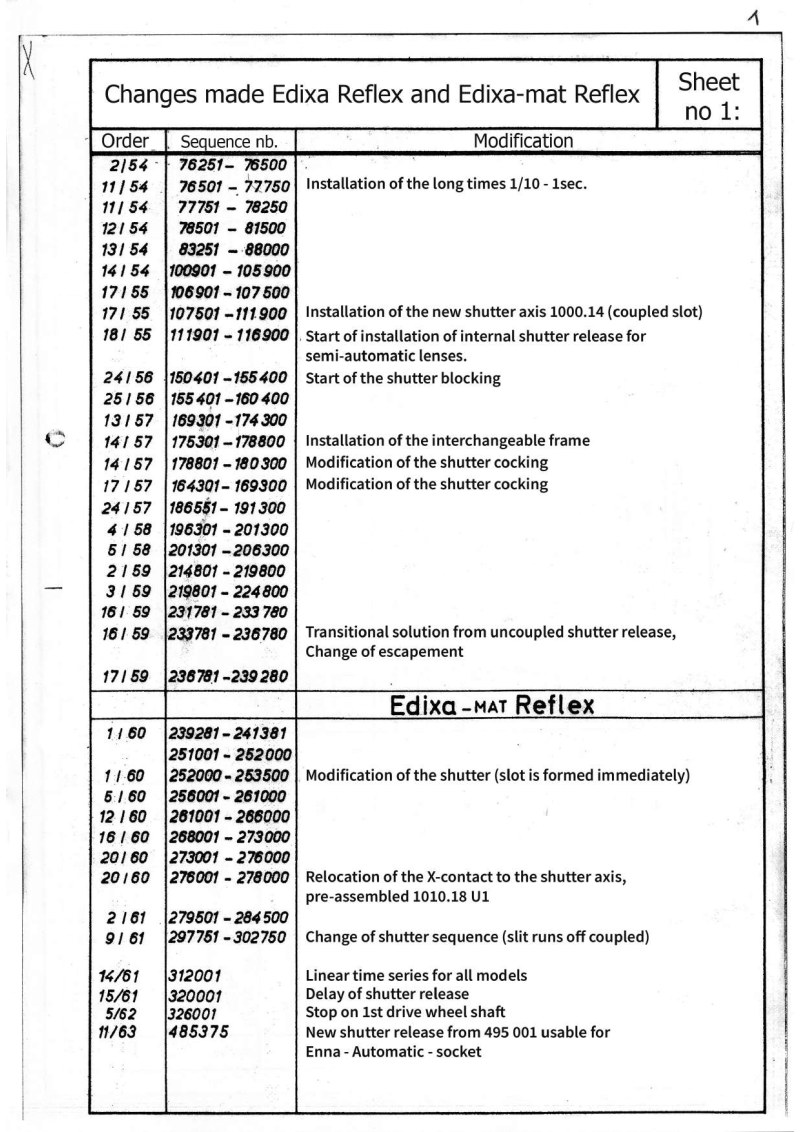
Comprehensive repair manual for EDIXA Reflex and EDIXA-mat Reflex cameras, specifically designed for professional repair shops and technicians. This detailed guide provides step-by-step instructions for disassembling, adjusting, and reassembling all major mechanical components of the camera. Coverage includes procedures for removing cover caps and base plates, regulator installation and setup, shutter speed adjustment across the 1/8 to 1 second range, M and X contact synchronization for flash, mirror box adjustment, and winding mechanism setup. Each section features precise technical specifications and schematic diagrams illustrating correct component positioning, required operating clearances, and alignment procedures. The manual addresses common errors and their root causes, alongside comprehensive troubleshooting guidance. Technical illustrations demonstrate proper part placement, functional tolerances, and detailed adjustment sequences. A modifications record documenting changes to these camera models is included at the front. An indispensable resource for technicians performing repairs or restorations on these professional-grade reflex cameras.
Table of Contents:
- 1. General information
- 2. Locking lever, riveted 1000.05 - U 24.
- 3. Contact lever 1000.05 - U 19 and U 20.
- 4. MX board and flash sockets 1000.05 -U2
- 5. Time setting lever 1000.05 - 98 Br
- 6. Shutter plate 1000. 11 release lock and release button
- 7. Time setting 1000.19 and safety axle S 581
- 8. Mounting parts and assemblies no. 2-7
- 9. Transport drum, mounted 1000.16
- 10. Winding axle, mounted 1000.17 (pre-assembly)
- 11. Locking axle, mounted 1000.18
- 12. Elevator axle, mounted 1000.17
- 13. Built-in parts and assemblies of no. 9 - 12
- 14. Roller blind, mounted 1000, U 5, U5 and U 10 (shutter adjustment)
- 15. Mounting bracket, mounted 1000.05- U 22
- 16. Adjusting M- and X-contact (synchronisation)
- 17. Brake lever 1000.05 - U 13 and driver lever 1000.05- U23
- 18. Mounting parts and assemblies no. 14 -17
- 19. Mirror box, mounted 1000.06, 1002.02 and 5 588
- 20. Right cover cap 1000.15
- 21. Left cover, 1000.6, rewind axle and rewind knob
- 22. Film stage 1000.05- 106
- 23. Back plate 1000.01
- 24. Built-in parts and assemblies of no. 19 - 23
- 25. Escapement 1000.07
- 26. Base plate 1000.03 and S 597
- 27. Lens connection ring 1000.14
- 28. Matte screen lens 1000.53
- 29. Built-in parts and assemblies of no. 25- 28
- 30. Exposure meter 2 M/ Wi
- 31. Advance mechanism 1000. 03
- 32. Built-in parts and assemblies no. 30- 31
- 33. Parts list of the assemblies with subassemblies and individual parts
Documentation must be downloaded on a computer (PC, Mac, or Linux).
Do not use a smartphone or tablet to download documentation; they generally lack sufficient memory capacity to handle large files, and few users know how to locate the download folder on these devices.
Once downloaded, you can use it right away and even print the pages you need, or use your smartphone in photo mode to translate into the language of your choice: Google Translate
Document Details
- Format
- Pages
- 55
- Size
- 8.0 MB
- Category
- Photography