Audio & HiFi - Service Manuals
Service manuals for Bang & Olufsen, Revox, Nagra, Studer, Rock-Ola — amplifiers, tape recorders, turntables, jukeboxes and Hi-Fi equipment. PDF.
Our Audio & Hi-Fi category brings together technical documentation for the great names in sound reproduction. High-end hi-fi and studio: Bang & Olufsen, Accuphase, Nagra, Studer Revox, Tandberg, Neumann. Consumer electronics: Pioneer, Kenwood, Marantz, Technics, Sony, Yamaha, Sansui. Vintage jukeboxes: Rock-Ola, Seeburg, Rowe, AMI, Wurlitzer. Professional tape recorders: Revox, Uher, TEAC, Akai. Service manuals, schematics and parts lists in PDF format.
Browse by Brand
ACCUPHASE
4 manuals
AKAI
15 manualsALPS
1 manualAMI
1 manualAMPEX
1 manualBANG & OLUFSEN
43 manualsBARTHE
1 manualCOOPER SOUND
4 manualsDENON
7 manualsDUAL
1 manualDYNAVOX
2 manualsGRUNDIG
39 manualsHARMAN KARDON
6 manualsKENWOOD
9 manualsKORG
2 manualsLENCO
5 manualsLPB
5 manualsLUXMAN
10 manualsMANLEY
1 manualMARANTZ
7 manualsMONTARBO
2 manualsNAD
1 manual
NAGRA
12 manualsNEUMANN
1 manualONKYO
3 manualsPANASONIC
1 manualPEAVEY
14 manualsPHILIPS
10 manuals
PIONEER
18 manualsROCK-OLA
5 manualsROLAND
1 manualROTEL
5 manualsROWE
1 manualSANSUI
25 manualsSANYO
1 manualSCOTT
43 manualsSEEBURG
20 manualsSHARP
1 manualSONORO
3 manualsSONY
7 manuals
STUDER REVOX
162 manualsTANDBERG
2 manualsTEAC
1 manualTECHNICS
11 manualsTELEFUNKEN
1 manual
TEPPAZ
19 manualsTHORENS
3 manuals
UHER
23 manualsWURLITZER
9 manualsYAMAHA
8 manualsZOOM
1 manualAll Audio & HiFi Manuals (50)
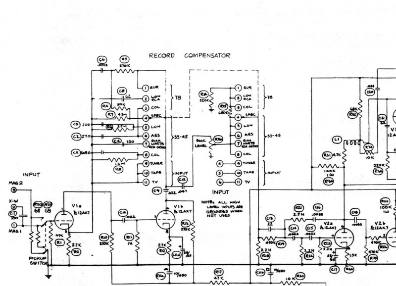
210-D Dynaural Amplifier Schematic
Complete electrical schematic diagram for the Scott 210-D Dynaural Amplifier — an essential service resource for technicians and enthusiasts restoring this classic tube amplifier. The schematic presents the full circuit architecture including the input stage, record compensator, dynamic range control circuit, bass and treble tone control sections, record monitor circuit, power output stage with tube complement, speaker connection topology, and complete power supply design. Component identification and interconnection routing are clearly marked throughout, enabling detailed troubleshooting, repair, and restoration work on this vintage audio component.
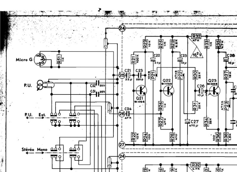
4TR10 Stereo Amplifier Electronic Schematic
Complete electronic schematic for the Barthe 4TR10 stereo amplifier, detailing the dual-channel left and right audio signal paths with full component-level circuit diagrams. Covers transistors, vacuum tubes (H.P. 8A), output transformers, resistors, capacitors, and all associated passive and active circuitry. Specifies power supply connections for 110V, 220V, 127V, and 240V inputs alongside output impedance ratings of 20 Kohms per Volt. Includes voltage reference table for alignment and quality control verification. Essential repair and maintenance reference for servicing this classic stereo amplifier design.
A700 Remote Control Tape Drive Operating Instructions
Operating instructions for the Revox A700 remote control unit, a specialized remote control system designed for synchronized slide presentations. This workshop manual covers remote operation of tape transport functions including rewind, fast forward, play, stop, and record modes. It explains slide synchronization control with sync-pulse recording capabilities, allowing you to advance slides in perfect timing with stereophonic audio playback. The manual details auxiliary functions such as repeat, automatic advance, and pause modes for flexible presentation control, and provides comprehensive technical guidance for simultaneous recording of sync-pulses alongside stereophonic sound tracks on both 4-track and 2-track recorders. Also included are sync-pulse cancellation procedures, detailed technical specifications for slide advance pulse recording, and a complete electrical schematic diagram of the remote control unit showing timer selector and pilot head connections. Essential service documentation for anyone operating or maintaining this professional slide-tape synchronization equipment.
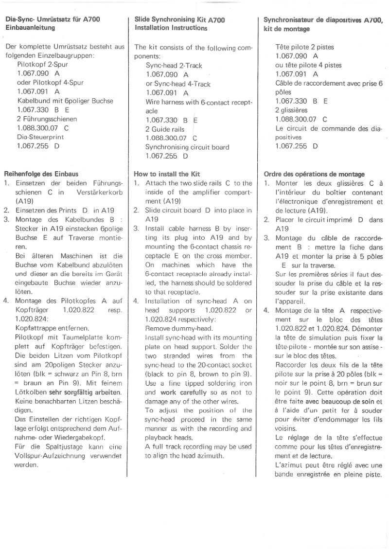
A700 Slide Synchronizer Kit - Installation & Schematic
Installation and schematic guide for the Revox A700 Slide Synchronizer Kit (model 1.067.255). This workshop manual provides complete assembly instructions for both 2-track and 4-track recorder configurations, a detailed component list, wiring diagrams, and circuit board layout with labeled test points and voltage specifications for troubleshooting and verification. Essential reference for technicians setting up or servicing this synchronization module.
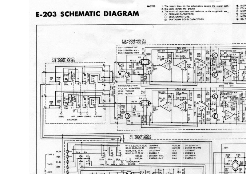
Accuphase E203 Schematic Diagram
Schematic diagram for the Accuphase E203 integrated amplifier. This single-page service reference provides detailed electronic circuit schematics with tube and transistor components, tracing the complete audio signal paths from input through the preamp and power amp stages, along with the power supply circuits and control sections. Essential for servicing, troubleshooting, or performing maintenance on the E203. Ideal as a companion to the full service manual for component-level repair work.
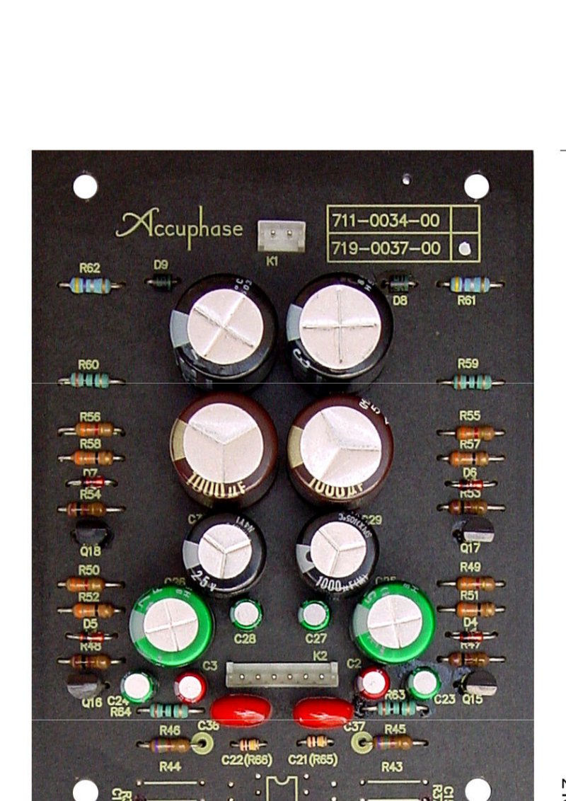
Accuphase E210 Schematic Diagram and Component List
Complete schematic diagrams and comprehensive parts list for the Accuphase E210 integrated amplifier. This technical documentation provides front panel layout, PCB component placement, equalizer assembly schematic detailing transistor configuration, power amplifier assembly schematic with tube complement, and full component specifications including manufacturer part numbers. An essential reference for anyone servicing or restoring this classic amplifier, offering the detailed circuit information and parts identification needed for maintenance, repair, or component replacement. Covers all signal stages from input through final output amplification.
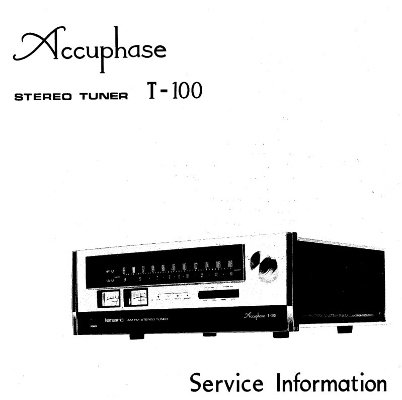
Accuphase T-100 Stereo Tuner Service Manual
Complete service and repair documentation for the Accuphase T-100 AM/FM stereo tuner, an essential workshop manual for technicians servicing this professional-grade receiver. This 24-page service manual delivers detailed block diagrams, external and internal component views, and exploded mechanical assembly illustrations that clarify the construction of all major circuits and subassemblies. Coverage includes the power supply, AM/FM front-end stages, intermediate-frequency amplifier modules, audio output sections, and dial tuning mechanism. Full schematic diagrams, technical specifications, and resistor color code references support accurate troubleshooting and circuit-level repair. Dedicated sections walk through meter replacement procedures and dial mechanism restringing, with component-level parts lists enabling precise identification of every resistor, capacitor, and mechanical element. A comprehensive parts list and technical reference material make this a complete repair guide for maintaining and restoring the T-100 to factory specifications.
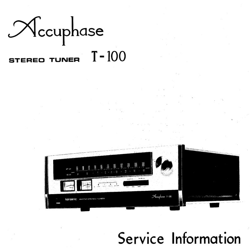
Accuphase T100 Stereo Tuner Service Manual
Comprehensive service manual for the Accuphase T100 stereo tuner, providing full technical documentation for technicians and experienced repair professionals. Covers block diagram architecture, external and internal construction views, detailed exploded parts diagrams, and step-by-step dial mechanism restringing procedures. Includes meter replacement guidance, power supply assembly breakdown with complete PCB layout schematics, front-end AM/FM circuitry with full component identification lists, delay fuse assembly details, multiplex and subcircuit assembly information, AM intermediate frequency stage assembly, audio amplifier section, detailed circuit descriptions, resistor color code reference, semiconductor lead identification, and the complete schematic diagram with full electrical specifications. Essential reference for maintenance, troubleshooting, and component-level repair of this classic high-fidelity AM/FM tuner. Table of Contents: - Block Diagram - External View - Internal View - Exploded View - Miscellaneous - How to Restring the Dial Mechanism - How to Replace the Meters - Power Supply Assembly - AM FM Front-End - FM Printed Circuit Board, AM Printed Circuit Board - Delay Fuse Assembly - FM IF and Meter Circuit Assembly - MPX and Subcircuit Assembly - AM IF Assembly - Audio Amp. Assembly - Circuit Description - Resistor Color Code - Semi-Conductor Leads - Schematic Diagram - Specifications
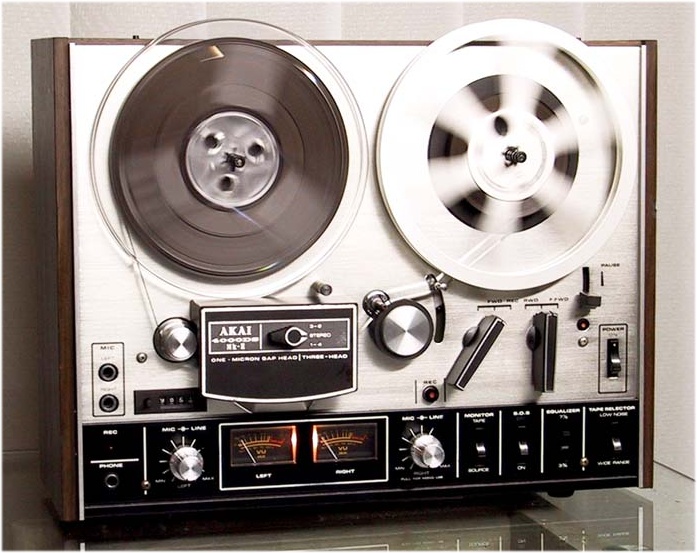
AKAI 4000 DS/DB Reel-to-Reel Descriptive Article
This descriptive article covers the AKAI 4000 DS/DB reel-to-reel tape recorder, a professional-grade audio recording and playback machine built to exacting standards. The guide walks through the unit's architecture, control layout, and operational modes—essential reading for technicians performing maintenance or repair work, as well as for vintage audio collectors and enthusiasts evaluating these machines. You'll find clear explanations of the recording and playback capabilities, the mechanical and electronic control elements, and the key performance characteristics that define this respected AKAI model. The content is organized to help you understand how the 4000 DS/DB functions across its various configurations, making it invaluable whether you're troubleshooting an issue, documenting specifications, or building knowledge of professional tape machine design from this era. A solid reference for anyone working with or collecting reel-to-reel recorders of this class.
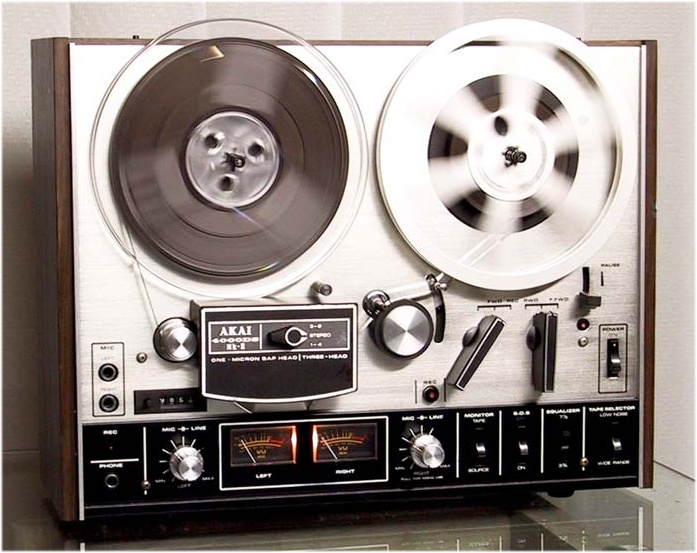
AKAI 4000DS MKII Troubleshooting Manual
Comprehensive troubleshooting and service documentation for the AKAI 4000DS and 4000DS Mark II stereo reel-to-reel tape recorder. This workshop manual brings together three critical sections essential for maintenance, repair, and diagnostics. The service manual section covers complete technical specifications and detailed measurement procedures including tape speed deviation, wow and flutter analysis, frequency response testing, signal-to-noise ratio verification, distortion measurement, crosstalk assessment, and erase ratio evaluation. Disassembly instructions walk through transport and amplifier unit removal step by step. Mechanical adjustment procedures address pinch wheel pressure tuning, supply and take-up reel assembly alignment, and recording and playback mechanism setup. Head alignment work encompasses height positioning, slant correction, and azimuth calibration across erase, recording, and playback heads. Amplifier adjustment guidance covers playback and recording level calibration, bias frequency tuning, bias voltage settings, high frequency deviation correction, and erase voltage specification. The parts list section organizes all components by functional block—head block, reel table block, motor block, and additional assemblies—with full reference numbering and visual component illustrations. Electrical documentation includes complete schematic diagrams and printed circuit board layouts with comprehensive component identification to support diagnostics and component-level troubleshooting.
Akai AM-2350 Stereo Integrated Amplifier Service Manual
Complete service manual for the Akai AM-2350 stereo integrated amplifier, a robust audio component rated at 35 watts per channel. This workshop manual provides everything needed for professional servicing: detailed technical specifications, full disassembly and reassembly procedures with step-by-step photographic guidance, and complete identification of all front and rear panel controls. Principal parts location diagrams and block schematics clarify signal flow through each amplification stage. You'll find level diagrams, input sensitivity and impedance data for phono, auxiliary, tuner, and tape inputs, frequency response plots, and tone control calibration ranges. Dedicated sections cover level meter adjustment procedures, including instrument connection diagrams and proper measurement technique. Printed circuit board composition is fully documented with detailed schematics for troubleshooting and component-level repair. An essential reference for anyone performing maintenance, alignment, or repair work on this classic integrated amplifier.
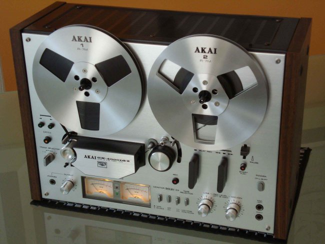
AKAI GX-4000 D/DB Troubleshooting Manual & Schematics
Comprehensive troubleshooting guide and schematic documentation for the AKAI GX-4000 D/DB professional stereo tape recorder. This service manual provides detailed circuit diagrams mapping the electronic architecture, including wiring schematics for amplifier circuits, microphone preamplifier stages, oscillation and recording sections, and mode control circuits. The schematics identify key active components including SC 458 LG and SC 945 L tubes in the amplification stages, along with audio transformers, gain control networks, and acoustic window assemblies. The manual includes tube equivalency tables and comprehensive front and rear panel connector diagrams with speaker connection wiring codes. An essential repair resource for technicians, electronics specialists, and collectors working on vintage tape machines from the 1960s–70s era.
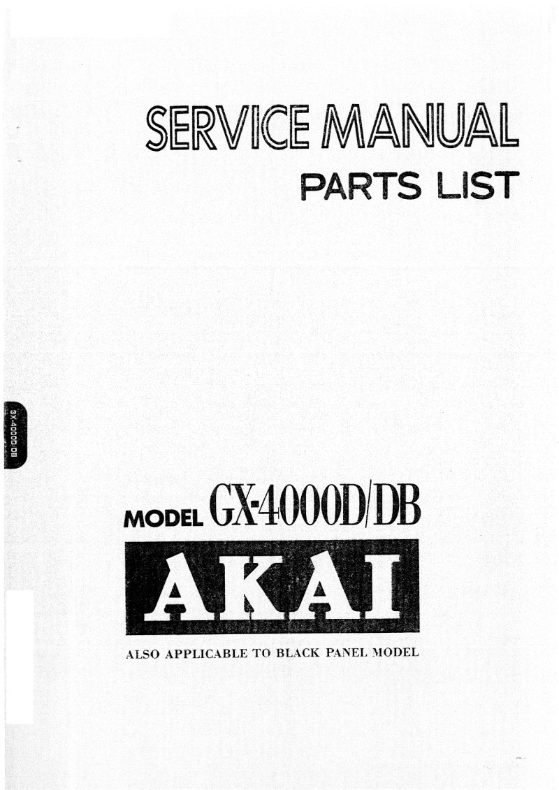
Akai GX-4000D/DB Stereo Tape Deck Service Manual and Parts List
Complete service manual and parts list for the Akai GX-4000D and GX-4000DB stereo tape decks. This workshop manual provides technical specifications for both models, detailed dismantling instructions with photographs, control panel layout documentation, and parts location diagrams. Mechanism adjustment procedures cover pinch roller pressure, reel table block tension, drive belt positioning, and head alignment. The manual includes amplifier adjustment charts, full schematic diagrams, and printed circuit board composition details. Coverage extends to head height, azimuth and angle alignment, playback and recording head specifications, and operating point adjustments for automatic shut-off functions. An essential maintenance reference for technicians servicing these professional-grade cassette decks.
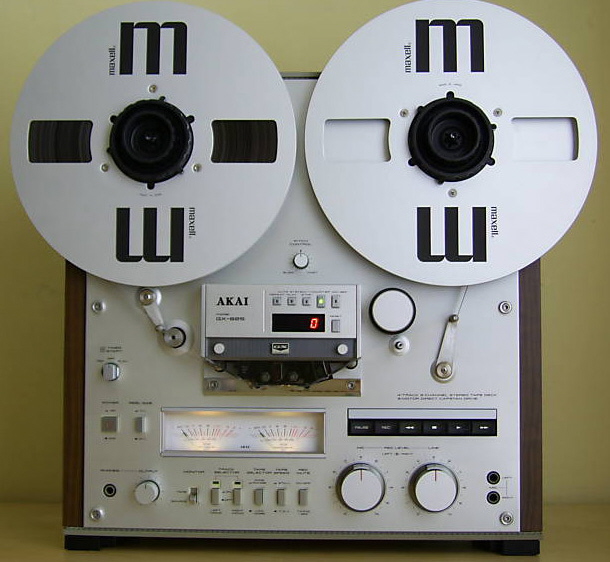
AKAI GX-625 Reel-to-Reel Repair Manual
Complete service manual for the AKAI GX-625 reel-to-reel tape recorder, essential for anyone performing maintenance or repair on this professional-grade audio equipment. This comprehensive workshop manual is organized into three major sections: detailed service information, an extensive parts list with illustrations, and complete electrical schematics. The service documentation covers full technical specifications including track configuration, reel capacity, tape speeds, and frequency response characteristics. Step-by-step dismantling procedures are provided with photographic guidance for removing the complete unit. All front and rear panel controls are identified and thoroughly explained. The manual details circuit operating principles across key systems: the LM8529 counter circuit, pulse generation mechanisms, servo braking, and capstan drive motor operation. Essential mechanical adjustments are documented with precision requirements for tape guide height alignment, reel table positioning, tension arm setup, and brake band calibration. DC resistance values for all motor coils and solenoids are tabulated for quick reference during troubleshooting. Printed circuit board classification data and AC inlet system information are included for multiple regional power cord configurations (CEE, JPN, CSA, AAL). Electrical schematics present detailed IC block diagrams and complete circuit layouts for all amplifier and control subsystems, making this repair manual an indispensable reference for technicians servicing the GX-625.
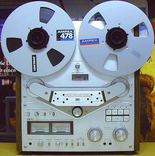
AKAI GX-635D Reel-to-Reel Troubleshooting Manual
Comprehensive service and troubleshooting manual for the AKAI GX-635D reel-to-reel tape recorder. This authoritative workshop reference covers all critical maintenance and adjustment procedures essential for professional servicing and restoration of this vintage tape transport. Detailed sections walk through transport mechanism calibration, including reel table height settings, capstan shaft loose play specification, and capstan tension regulation to ensure reliable tape speed stability. The brake system receives thorough coverage with precise instructions for brake band positioning and tension adjustment (550 ± 50 g), complemented by microswitch alignment guidelines for consistent braking response. Roller block adjustment procedures address guide roller loose play tolerances and tension microswitch calibration to maintain smooth tape guidance. Pinch roller positioning, pressure adjustment, and verification procedures ensure proper tape contact and consistent transport performance. Pause plunger calibration receives dedicated attention for accurate function. Complete technical illustrations, full wiring schematics, and control system diagrams support every maintenance operation with visual clarity. Parts list and detailed component specifications enable accurate identification and replacement of worn elements. An essential troubleshooting and parts reference for audio technicians, recording engineers, and vintage tape recorder enthusiasts undertaking professional-level service work on this legendary machine.
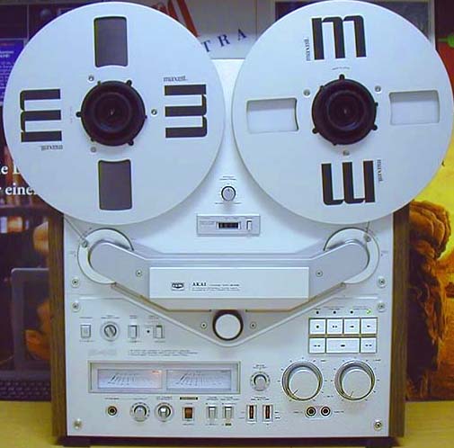
AKAI GX-646 Reel-to-Reel Troubleshooting Manual
Comprehensive service manual for the AKAI GX-646 stereo reel-to-reel tape deck, covering both standard and black panel model variants. This professional workshop manual is organized into three core sections: detailed service procedures, complete parts list, and full electrical schematic diagrams. The service documentation includes precise adjustment instructions for all critical mechanical systems: reel table height, capstan shaft play, pinch roller positioning and pressure in both play and pause modes, brake band alignment and tension, and complete head alignment for playback, recording, and erase functions. Every adjustment procedure is accompanied by detailed technical illustrations with exact millimeter specifications to ensure proper calibration. Technical data for the Capstan motor (SCM-20D) and comprehensive tape guide adjustment guidelines are included throughout. The parts list provides clear identification of all deck components for accurate replacement and sourcing. Complete electrical schematics document the power supply, control circuits, microphone amplifier, equalization networks, and all auxiliary circuits needed for thorough troubleshooting and repair of the entire unit. An essential reference for technicians and experienced users maintaining this classic tape deck.
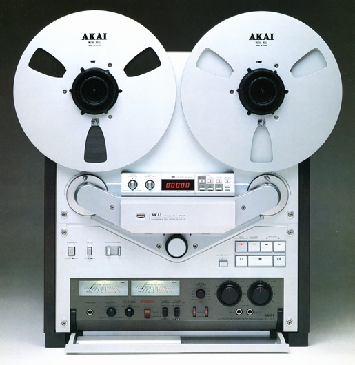
AKAI GX-747 Reel-to-Reel Troubleshooting Manual
Comprehensive troubleshooting and repair manual for the AKAI GX-747 reel-to-reel tape recorder. This workshop manual provides everything needed to service and maintain this professional-grade 4-track, 2-channel stereo system with 10-inch reel capacity. The document is organized into three core sections: a detailed service manual with full technical specifications, a complete parts list with reference illustrations, and comprehensive electrical schematics. The service section covers systematic disassembly procedures and detailed identification of all controls and mechanical assemblies. You'll find in-depth explanations of the recording and playback circuits, electronic control systems, and motor brake operation. The manual walks through precise mechanical adjustments including guide roller clearance, microswitch positioning, reel table height, capstan shaft slack, brake band alignment, and pinch roller pressure—each adjustment explained with the tolerances and tools required. A dedicated electrical adjustment section addresses clock frequency calibration, phototransistor sensitivity tuning, and DC resistance verification across the circuit. The parts catalog systematically organizes over 200 individual components by functional block, with clear reference diagrams showing how each part fits into the transport and electronic systems. Complete electrical schematics include integrated circuit diagrams and full power and control circuit layouts, making it straightforward to trace signal paths, identify component failures, and verify circuit operation. Whether you're diagnosing transport problems, audio issues, or electronic faults, this manual provides the technical foundation to understand how the GX-747 works and how to restore it to proper operation.
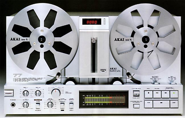
AKAI GX-77 Reel-to-Reel Troubleshooting Manual
Comprehensive troubleshooting and repair manual for the AKAI GX-77 stereo reel-to-reel tape recorder. This detailed service manual covers every aspect of maintaining and diagnosing faults in this professional-grade audio equipment. You'll find essential safety guidance, step-by-step mechanical and electronic adjustment procedures, and technical diagrams that walk you through fault identification. The manual is structured around three core sections: the service manual itself, which explains operating principles and how each mode functions; a complete parts list with technical illustrations showing how each assembly unit is constructed; and full electrical schematics including system block diagrams and detailed printed circuit board layouts. The adjustment procedures address practical work—setting brake band position, adjusting mechanical tension, aligning playback and recording heads, calibrating the servo motor, and tuning the amplifier. You also get technical specifications for winding resistances and safety-critical components. Throughout, timing diagrams, mode-specific terminal conditions, and output waveform specifications help you verify correct performance. This is the go-to reference for maintenance technicians, repair professionals, and experienced enthusiasts who service vintage tape machines. The combination of detailed parts identification, circuit descriptions, and systematic adjustment guidelines makes it invaluable for both routine upkeep and complex troubleshooting work.
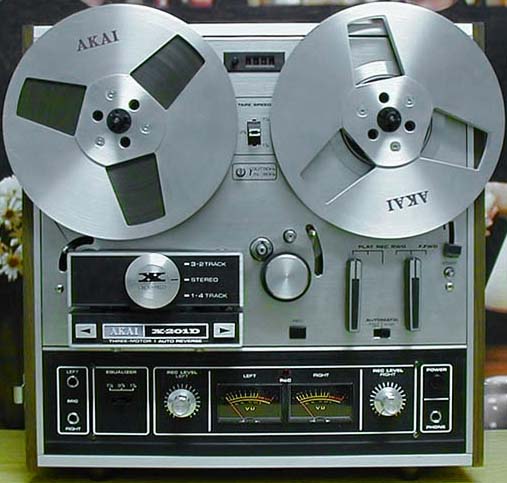
AKAI X-200D & X-201D Reel-to-Reel Troubleshooting Manual
Complete troubleshooting and operating manual for the AKAI X-200D and X-201D stereo reel-to-reel tape recorders. This comprehensive workshop manual provides detailed technical guidance for diagnosing, maintaining, and operating these professional-grade audio machines. The service manual begins with clearly illustrated control panel identification and labeling, followed by thorough explanations of the proprietary Crossfield™ recording technology, the 4-track stereo recording system, and available tape speeds (19, 9.5, and 4.75 cm/s). Dedicated sections address all essential recording and playback functions—stereo and mono recording, playback operation, fast forward and rewind switching systems, automatic stop mechanisms, and tape transport control. Practical instructions cover microphone recording, recording from external audio sources, transcription workflows, and direct record player integration. The maintenance guide includes procedures for magnetic head cleaning, demagnetization of tape path components, and equalizer calibration. A substantial technical section provides complete performance specifications and electrical data. Extensive professional schematics and functional block diagrams illustrate the internal circuitry and mechanical design of both models. Warranty documentation and user registration information are included. An essential reference for service technicians, maintenance engineers, and experienced operators requiring authoritative documentation of these precision stereo recording systems.

AKAI X-200D Service Manual
Service manual for the AKAI X-200D tape recorder. This workshop manual provides schematic diagrams and technical specifications needed for troubleshooting, maintenance, and repair work. Includes detailed electronic schematics and component-level guidance for qualified technicians servicing this model.

Akai X-201-D Service Manual
Service manual for the Akai X-201-D audio equipment. This workshop manual consists entirely of blank pages, which may indicate a reproduction or archival copy where the original content was not successfully captured or printed. Despite the blank interior, this document retains value for collectors and enthusiasts seeking to complete a documentation set for this model. The X-201-D is a vintage Akai audio device, and locating any service documentation—even incomplete copies—can be challenging. Suitable for reference purposes or as a placeholder in a complete repair manual collection.
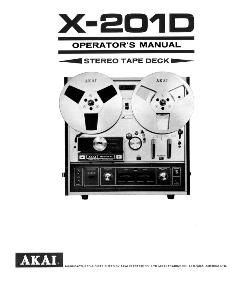
Akai X-201D Stereo Tape Deck Operator's Manual
Complete operator's manual for the Akai X-201D stereo tape deck, a professional reel-to-reel tape recorder built for serious audio work. This service and maintenance guide covers everything you need to operate this machine—detailed control descriptions, voltage and cycle conversion settings for use anywhere in the world, tape loading procedures, and tape speed selection with equalizer adjustments. You'll find thorough instructions for recording and playback in stereo and monaural modes, with particular attention to the X-201D's cross-field head recording system that delivers extended frequency response. The manual walks you through automatic and manual reverse playback, pause control, fast forward and rewind operations, and monitoring functions. Technical specifications, operating precautions, and troubleshooting sections address common issues like dirty erase heads or magnetized heads, with detailed steps for head cleaning and demagnetization. Diagrams show the control layout, rear panel connections, and correct tape threading—everything you need to get consistent performance from this professional-grade tape recording equipment. An essential workshop reference for any operator working with this classic transport.
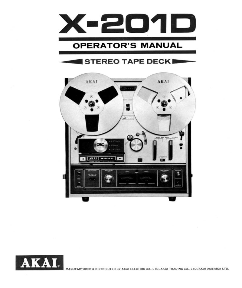
Akai X-201D Stereo Tape Deck Operator's Manual
Complete operator's manual for the Akai X-201D stereo tape deck, serving as an essential repair and maintenance reference for users and technicians. Provides detailed guidance on identifying and operating all front-panel controls, understanding the cross-field head recording system for enhanced audio fidelity, configuring voltage and cycle conversion settings for different regional power standards, and executing proper tape loading procedures. Covers tape speed selection with corresponding equalizer settings to optimize playback quality across different tape formulations, fast forward and rewind operation, automatic stop and shut-off features to protect tape and equipment, and pause control functionality. Details the 4-track recording and playback system capable of stereo or monaural operation modes, automatic and manual reverse playback options for convenient tape navigation, and recording techniques from microphone inputs and external audio sources. Includes essential maintenance procedures such as tape splicing and editing methods, head cleaning protocols, and demagnetizing techniques to preserve recording and playback performance. Supplemented with complete technical specifications and standard accessories information to support troubleshooting and component identification.
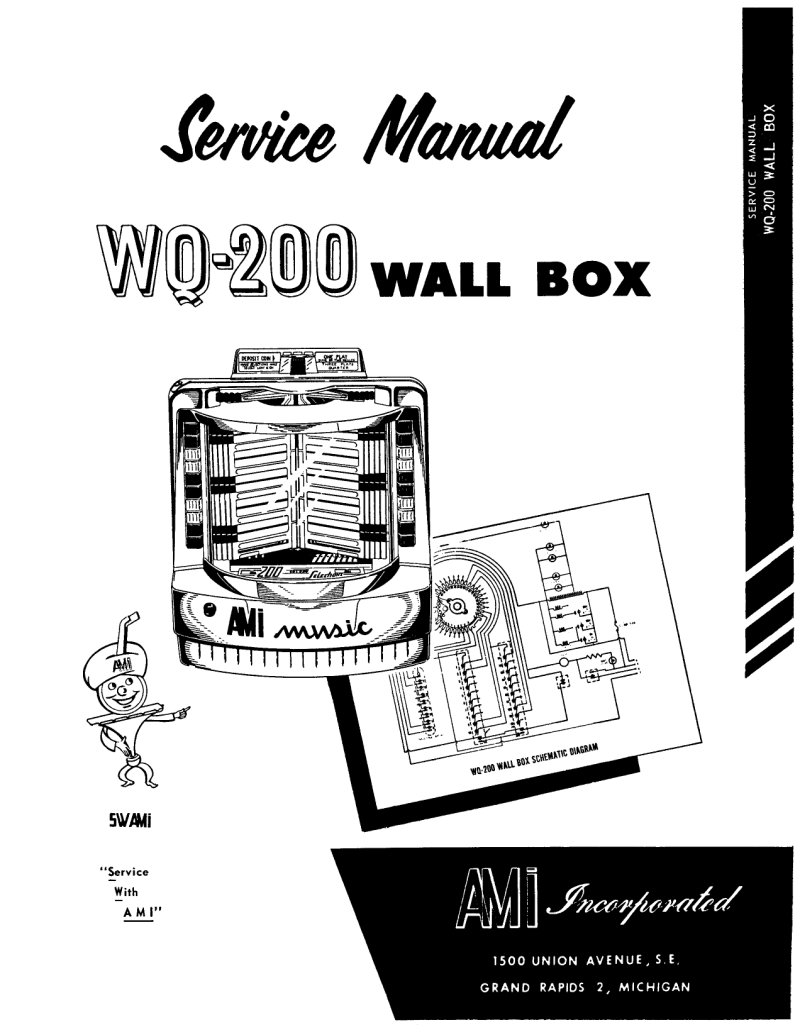
AMI WQ-200 Wall Box Service Manual
Service manual for the AMI WQ-200 wall box, a remote control unit designed to interface with the G-200 phonograph. This workshop manual covers operating principles, the credit unit mechanism, motor control switch adjustment procedures, wiper arm positioning, pushbutton bank controls, and wall box connection diagrams. Includes mechanical adjustment specifications and detailed circuit operation information for managing pulse transmission to the phonograph unit. An essential repair and maintenance reference for technicians working with AMI remote jukebox control systems.
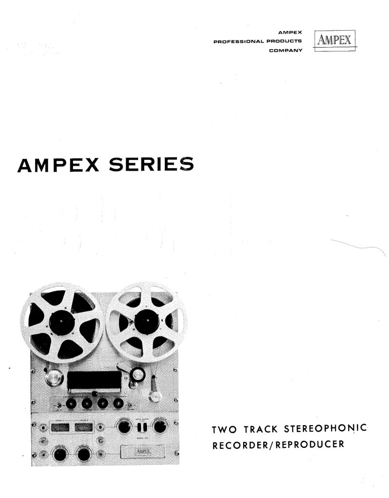
Ampex Series 354 Two-Track Stereophonic Recorder/Reproducer Manual
Complete service manual for the Ampex Series 354 two-track stereophonic tape recorder/reproducer, a professional-grade instrument from 1960. This comprehensive workshop guide covers operation and maintenance in full detail, including machine description and performance characteristics, installation procedures, and operational techniques for studio and broadcast environments. The manual provides thorough coverage of tape transport mechanisms, head assemblies, and electronic circuits—record and reproduce amplifiers, bias and erase oscillators, and power supply systems. Technical specifications document tape width of 1/4 inch, speed pairs of 3 3/4-7 1/2 ips and 7 1/2-15 ips, frequency response, signal-to-noise ratios, and flutter and wow measurements across each speed setting. Dedicated sections address the physics of magnetic tape recording, tape transport maintenance and calibration adjustments, troubleshooting procedures for record and reproduce amplifier circuits, and comprehensive parts lists for both electronic assemblies and mechanical tape transport components. An essential reference for technicians maintaining or restoring this classic professional recorder.
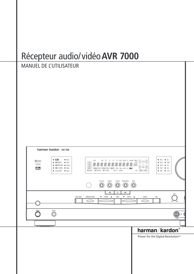
AVR 7000 Audio/Video Receiver User Manual
Complete user manual for the Harman Kardon AVR 7000 audio/video receiver. This comprehensive guide covers all aspects of setup and daily operation: front and rear panel controls, surround mode configuration including Logic 7 and VMAX processing, speaker placement and calibration, AM/FM tuner operation with RDS data functionality, remote control programming, and multi-room control system management. Detailed sections address Dolby Digital and DTS decoding, HDCD playback on compatible sources, discrete 5.1 channel inputs, and digital audio I/O specifications. Troubleshooting section helps diagnose and resolve common issues. Essential reference for installation, configuration, and maintenance of this high-end home theater receiver.
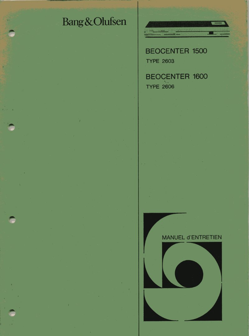
Bang & Olufsen Beocenter 1500/1600 Service Manual
Complete service manual for the Bang & Olufsen Beocenter 1500 (Type 2603) and Beocenter 1600 (Type 2606) audio receivers. This workshop manual provides the technical foundation needed to service and repair these integrated amplifier-tuner units, with detailed schematic diagrams showing complete signal paths from tuner input through tape recording circuitry to speaker output stages. Precise component identification is provided throughout, along with DC voltage measurement points at critical nodes and alignment procedures for both FM and AM tuner sections, including sensitivity specifications. The tape recorder section covers recording and playback electronics in detail, including left and right channel amplification stages, output transformer configurations, and load conditions. Technical specifications include resistor tolerances, polyester and ceramic capacitor ratings, and measurement conditions across the full output level range. An essential reference for technicians performing alignment, troubleshooting, component replacement, and understanding the complete electronic architecture of these receivers.
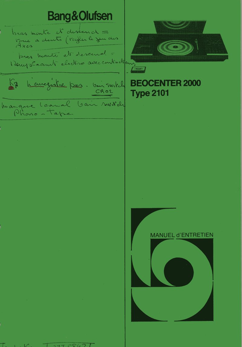
Bang & Olufsen Beocenter 2000 Type 2101 Service Manual
Complete service manual for the Bang & Olufsen Beocenter 2000 Type 2101, a premium integrated audio system combining turntable, cassette deck, and receiver in one sophisticated unit. This workshop manual provides the electrical schematics and circuit diagrams essential for professional technicians performing maintenance and repair work on this Danish-manufactured equipment. The documentation covers main amplifier circuits, power supply design, tone control and equalization stages, recording and playback amplifiers for both channels, and the turntable and tape deck subsystems built into the unit. Detailed circuit diagrams show preamplifier stages, phono input circuits, microphone inputs, and complete stereo output amplification featuring Dolby noise reduction. Technicians will find comprehensive schematic pages mapping all major functional blocks and component-level circuit information needed for proper troubleshooting and servicing of this high-end audio system.
Bang & Olufsen Beocenter 2300 Service Manual
Complete service manual for the Bang & Olufsen Beocenter 2300 audio receiver, covering all variants from model 2611 through 2620. This workshop manual provides detailed circuit diagrams and schematics essential for servicing and repairing this premium audio equipment. Diagram A maps the complete FM/AM tuner front-end circuitry, including RF and IF decoder stages with full component detail. Diagram F presents the microcomputer control architecture built around the IC5 PCF8583 processor, with memory organization and data bus routing clearly marked. Diagram G covers the display and keyboard interface system, featuring the eight-character LCD display with contrast voltage regulation and LED backlight driver circuits. The manual also documents muting and stereo detection circuits, signal processing amplifier stages, and detector configurations throughout the signal chain. Every schematic page includes component designations, reference values, and connection points needed to diagnose and repair this receiver effectively.

Bang & Olufsen Beocenter 2800 and 4600 Service Manual
Complete service manual for the Bang & Olufsen Beocenter 2800 (Type 2630) and Beocenter 4600 (Type 2631) audio receivers. This comprehensive workshop documentation covers repair, adjustment, and maintenance procedures for these high-end integrated amplifiers and tuner systems. Includes detailed circuit diagrams and schematics for FM and AM tuner sections, power amplification stages, tape recording electronics, and control circuits. Test point measurements and voltage reference specifications support systematic troubleshooting and bench alignment. Full system schematics paired with individual module diagrams allow technicians to trace signal flow, identify components, and verify interconnections with precision. Essential reference for electronics technicians and service professionals maintaining vintage Bang & Olufsen audio equipment.

Bang & Olufsen Beocenter 3300 Type 1604 Service Manual
Complete service manual for the Bang & Olufsen Beocenter 3300, model 1604. This workshop repair documentation provides comprehensive technical guidance for maintaining and troubleshooting this integrated stereo receiver system. The manual covers circuit diagnosis, index drive operation, and preset tuning adjustment procedures essential for field service work. Detailed electrical schematics illustrate component placement, tuner circuits, stereo decoder topology, and amplification stages. Full-color PCB circuit diagrams show component values and color-coded part identification, with dedicated connector and socket location drawings for accurate assembly reference. Sections on power supply design and control circuitry logic support efficient fault isolation and component verification. Technical illustrations clarify the internal architecture across all major subsystems: electronic modules, power transformers, amplifier stages, and tuner control mechanisms. Dedicated sections address maintenance and repair of the magnetic tape transport system, supplemented by complete signal flow diagrams and intercircuit connections throughout the receiver. An index guides technicians to specific systems and adjustment points for rapid problem resolution.

Bang & Olufsen Beocenter 5000 Service Manual Types 1802-1804
Complete service manual for the Bang & Olufsen Beocenter 5000 audio receiver, covering model types 1802 and 1804. This workshop documentation delivers the technical depth required for professional repair and maintenance of these high-end integrated amplifiers. Five detailed circuit diagrams form the core of the manual, breaking down the tuner front-end, amplification stages, stereo decoder circuits, power supply topology, and control logic. You'll find full schematic diagrams for all electronic circuits, precise component identification with values, and wiring layouts across both channels. The troubleshooting section walks through diagnosis procedures that service technicians rely on to isolate faults in audio output, tuning performance, and power delivery. Bilingual presentation in English and French makes this repair reference accessible to technicians across European markets. Essential for anyone maintaining or restoring these classic Beocenter units to original specification.
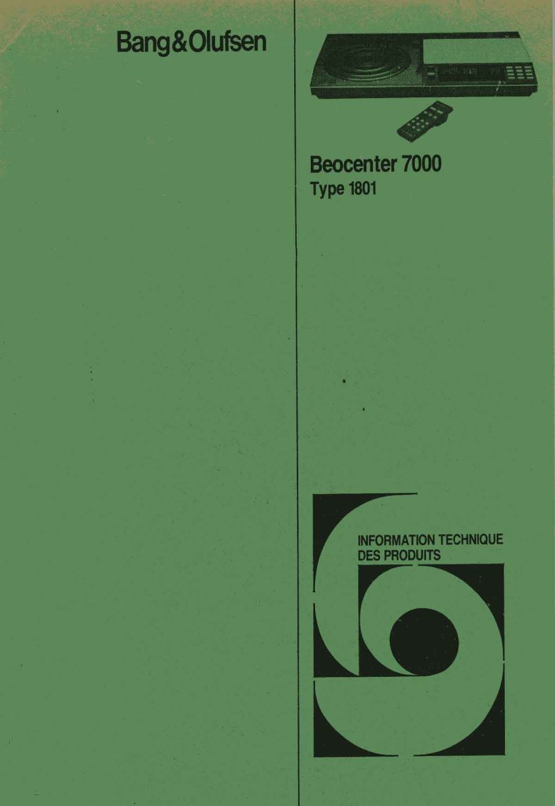
Bang & Olufsen Beocenter 7000 Type 1801 Service Manual
Complete service manual for the Bang & Olufsen Beocenter 7000 Type 1801, a premium integrated audio receiver and turntable system. This technical documentation provides everything needed for systematic maintenance, troubleshooting, and repair of this sophisticated equipment. Detailed schematic diagrams cover the tuner section, amplifier stages, stereo decoder circuits, control modules, and FM preset mechanisms with all component values clearly marked. Comprehensive block diagrams trace signal flow through the amplification chain and control logic, essential for understanding system operation during diagnostics. The manual includes specific procedures for lamp replacement, hinge adjustment, and index drive mechanism specifications, along with function tables documenting control module states across playback, recording, and preset tuning modes. Circuit schematics span multiple pages to capture the full complexity of this receiver's design. This workshop manual is the authoritative reference for qualified technicians performing restoration, repair, or detailed maintenance on this classic Bang & Olufsen audio system.
Bang & Olufsen Beocord 1700/2200 Service Manual
Comprehensive service manual for the Bang & Olufsen Beocord 1700 and 2200 tape recorders (types 4603 and 4601), designed as an essential workshop reference for technicians performing maintenance and repair of these professional-grade audio recording systems. The manual provides complete electrical schematics and circuit diagrams throughout, with every component clearly numbered and referenced so you can quickly locate specific stages—amplification, recording, playback, motor control, and power supply circuits. Component values and part numbers are marked directly on each schematic, eliminating guesswork during troubleshooting or component replacement. The detailed block diagrams break down the signal path and mechanical control architecture, making it straightforward to diagnose faults, perform alignments, and restore full functionality. Whether you're tracking down an intermittent audio issue, replacing worn resistors or capacitors, or verifying motor speed regulation, this documentation gives you the precise technical information needed to complete the job correctly. An indispensable reference for any shop handling these premium tape recorder models.
Bang & Olufsen Beocord 6000 Service Manual
Complete workshop and service documentation for the Bang & Olufsen Beocord 6000 tape recorder and the full Beocord series. This professional-level repair manual covers the Beocord 6000 (Types 4831–4837), Beocord 8002 (Types 4841–4847), Beocord 6002 (Types 4851–4857), and Beocord 8004 (Types 4861–4867) in full technical detail. The manual provides circuit schematics, component location diagrams, and detailed electrical specifications for all amplifier stages, bias rectifier circuits, and Dolby noise reduction implementation. Technicians will find complete pin configurations and function tables for integrated circuits, functional operation tables for microcomputer control systems, and specifications covering the various recording formats these decks support. This is the authoritative technical reference for anyone servicing or maintaining these professional recording machines.
Bang & Olufsen Beogram 1102-1902 Service Manual
Complete service and maintenance manual for the Bang & Olufsen Beogram 1102-1902 turntables, covering both Type 5715 and 5711 models. This technical documentation includes detailed electrical schematics and circuit diagrams showing all internal components and wiring configurations essential for understanding the turntable's electronics. A comprehensive electrical parts list identifies resistors, capacitors, inductors, transformers, and diodes with their specific part numbers and specifications for accurate component replacement and sourcing. The manual provides three focused sections on tonearm adjustment: basic tonearm setup with proper disc placement and 3 mm spacing adjustment, balanced tonearm configuration for optimal tracking force, and parallelism adjustment procedures using calibration tools. Technical diagrams illustrate pickup arm positioning and mechanical adjustment mechanisms. An invaluable reference for technicians performing maintenance, repairs, or restoration work on these classic Bang & Olufsen turntables.
Bang & Olufsen Beogram 1700 Service Manual
Comprehensive service manual for Bang & Olufsen Beogram 1700 turntable models 5731 and 5733, covering complete technical documentation for repair and maintenance work. The manual extends support to three additional Beogram models: 2202 (Type 5741), 2402 (Type 5742), and 3404 (Type 5747). Full circuit schematics are provided for power supply, motor control, switching mechanisms, and audio amplification stages. Detailed pickup arm schematics include contact pin configurations and operational specifications for turntable speeds at different RPM settings. A printed circuit board layout diagram shows the copper-foil side view with precise component placement. The documentation covers both mechanical and electrical systems with reference guides enabling technicians to identify components and troubleshoot issues systematically. This workshop manual serves as an essential resource for anyone performing adjustments, repairs, or routine maintenance on these classic Bang & Olufsen turntable models.

Bang & Olufsen Beogram 6000 Service Manual
Complete service and maintenance manual for the Bang & Olufsen Beogram 6000 record player, covering models Type 5751, 5753, and 5754. This technical workshop manual provides detailed guidance on installation, adjustment, and operation of the turntable system for service technicians and maintenance personnel. The manual includes comprehensive information on pickup arm assembly, with specific instructions for height adjustment, balance calibration, and parallelism verification—critical for accurate tracking and stylus alignment. Technical sections cover proper placement and handling of 30 cm records with detailed diagrams showing platter assembly and transport safety locks to prevent damage during shipping and setup. Pickup arm adjustment procedures are illustrated with precise technical drawings demonstrating correct spacing and alignment requirements for optimal performance. Additional content includes full schematic diagrams of the electronic circuitry and a detailed function table for the Datalink decoder system, enabling technicians to understand control signals and operational parameters. An essential reference for anyone responsible for maintaining or repairing this premium audio equipment.
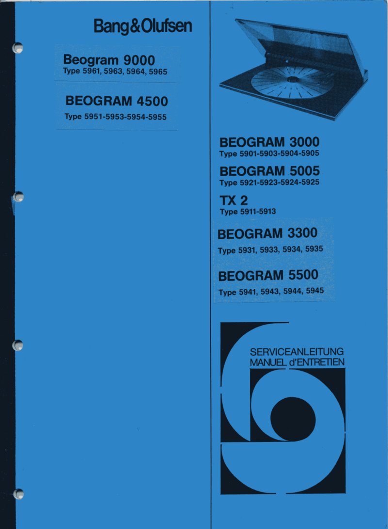
Bang & Olufsen Beogram 9000 Service Manual
Comprehensive service manual for the Bang & Olufsen Beogram 9000 turntable and related models (types 5961, 5963, 5964, 5965), along with documentation covering the Beogram 4500, Beogram 3000, Beogram 5005, TX 2, Beogram 3300, and Beogram 5500 product lines. This workshop manual provides detailed electrical schematics and circuit diagrams essential for maintenance and repair of these vintage turntables. Technical sections cover motor control systems, servo motor mechanisms, and complete electronic circuit layouts with precise component specifications. Originally published in German with multilingual support, this is essential reference material for service technicians and qualified repair professionals working on classic Bang & Olufsen audio equipment. Includes complete troubleshooting data and technical specifications for comprehensive turntable servicing.
Bang & Olufsen Beomaster 1100 Type 2609 Service Manual
Complete technical service manual for the Bang & Olufsen Beomaster 1100 Type 2609 integrated amplifier and tuner. This workshop documentation provides detailed schematic diagrams, circuit board layouts, and comprehensive component specifications essential for service, maintenance, and repair work. The manual covers the FM tuner circuit architecture, amplification stages for both left and right channels, and all control systems with precise component values, tube and transistor identifications, and interconnection diagrams needed for proper assembly and troubleshooting. Technical specifications include FM reception sensitivity, frequency response measurements, audio level calibration points, brightness adjustment procedures, and mechanical switch configurations. A valuable resource for technicians and service professionals working on classic Bang & Olufsen audio equipment restoration and long-term maintenance.
Bang & Olufsen Beomaster 2200 Type 1601 Service Manual
Comprehensive service manual for the Bang & Olufsen Beomaster 2200 Type 1601, a premium FM/AM stereo receiver from the renowned Danish manufacturer. This workshop documentation provides detailed schematic diagrams across multiple circuit boards, covering the tuning circuit, stereo decoder, audio amplification stages, and power supply architecture. Component-level circuit diagrams display all resistors, capacitors, transistors, and integrated circuits with clear labeling. Technical specifications and troubleshooting guidance support field diagnosis and repair procedures. The manual includes complete PCB layouts and interconnection schematics for major functional blocks: left and right audio channels, phono input stages, tape recorder interface circuits, and the full power supply module. An invaluable reference for technicians and service engineers needing to understand the Beomaster 2200's internal design and operation at the repair and maintenance level.
Bang & Olufsen Beovox Beolab Service Manual - Circuit Diagrams
Comprehensive service manual with complete circuit diagrams and technical schematics for Bang & Olufsen Beovox Beolab loudspeaker systems. Essential reference documentation for technicians and experienced users performing maintenance, troubleshooting, and repair work on these premium audio components. Includes detailed electrical diagrams to support component-level diagnostics and circuit analysis.
Bang & Olufsen Beovox/Beolab Service Manual
Complete service manual for Bang & Olufsen Beovox 3000, 5000 and Beolab speaker systems. This workshop documentation covers technical repair and maintenance procedures for these premium audio components, including detailed troubleshooting guidance, internal schematic diagrams, and component-level repair information. Essential reference for technicians servicing B&O speaker systems and audio enthusiasts undertaking speaker restoration or maintenance work. Covers electrical circuits, mechanical assembly, driver replacement, and system calibration procedures.
Beocenter 1400 Type 2604 Service Manual
Comprehensive service manual for the Bang & Olufsen Beocenter 1400 Type 2604 audio receiver, covering complete disassembly, troubleshooting, and maintenance procedures essential for workshop and field service. This technical documentation provides detailed guidance on cursor drive mechanisms and includes precise calibration data using the B&O RV7 voltmeter within the X1 measurement scale. The manual specifies output and power transistor characteristics—including models 2TR22, 2TR23, 2TR25, and 2TR33—with impedance, winding configurations, and exact ohmic measurements for accurate diagnostics. Multiple schematic diagrams illustrate the MF/IF/ZF decoder section, LF/AF/NF audio amplification circuits, and tape recorder assembly integration. Capacitor designations clearly distinguish polysterene, metallized plastic, plaquette, high-Q ceramic, and ceramic types, ensuring correct component replacement during repairs. FM sensitivity measurements are documented at specified output levels and frequencies, with voltage and impedance data provided for normal operating conditions and tape recorder engaged mode. An indispensable reference for technicians performing alignment, circuit analysis, and restoration work on this compact receiver system.
Beocenter 3500 Type 2401 Service Manual
Complete service manual for the Bang & Olufsen Beocenter 3500 Type 2401 turntable system. This technical workshop documentation provides detailed schematic diagrams, wiring layouts, and component identification necessary for troubleshooting and repair work on this classic stereo audio equipment. The manual includes comprehensive circuit diagrams across multiple pages with precise electrical specifications, voltage references, and measurement points clearly marked for technician reference. Two main diagram sections illustrate the full audio system architecture, covering stereo amplification stages, control circuits, and turntable interface components. Both mechanical and electrical aspects of the unit are addressed, making this an essential repair guide and reference resource for service technicians working on Bang & Olufsen audio systems of this era.

Beocenter 4000 Type 1603 Service Manual
Comprehensive service manual for the Bang & Olufsen Beocenter 4000 Type 1603 receiver. This technical documentation supplies detailed circuit diagrams, component schematics, and maintenance procedures essential for servicing this professional audio equipment. The workshop manual presents multiple pages of electrical schematics organized into numbered diagrams covering power supply, tuner circuits, amplification stages, and control systems. Each schematic displays precise component values, part identifications, and interconnection details required for effective troubleshooting and repair work. A legend clarifies connector symbols and pin arrangements on the baseplate, accompanied by comprehensive socket and plug placement surveys for accurate reassembly. Technical specifications document voltage supplies spanning ±5.7V to ±30V, with detailed information on transformers, amplification circuits, and switching mechanisms throughout the unit. Whether you're diagnosing an intermittent fault or performing complete restoration on this vintage Bang & Olufsen audio center, this repair manual provides the schematic-level detail technicians need for informed service decisions.
Beocord 1200 et 1600 Type 4207 et 4205 Service Manual
Comprehensive service manual for the Bang & Olufsen Beocord 1200 and 1600 reel-to-reel tape recorders, Type 4207 and Type 4205 models. This workshop documentation provides the technical depth required for professional repair and restoration of these vintage analog recording systems. Included are complete electrical schematics with full component layouts, detailed wiring diagrams, pinout references for individual modules, and mechanical assembly guidance. All transistor, integrated circuit, capacitor, and resistor specifications are listed with corresponding part numbers, making component identification and replacement straightforward. The manual features multiple schematic pages covering both model variants, allowing technicians to distinguish between standard and enhanced configurations with precision. Suitable for anyone undertaking restoration, troubleshooting, or preventive maintenance on classic B&O tape deck equipment.
Beocord 6500 Tape Deck Version II Service Manual
Complete service manual for the Bang & Olufsen Beocord 6500 Tape Deck Version II, essential technical documentation for anyone maintaining, repairing, or troubleshooting this professional-grade cassette recording and playback system. The workshop manual covers the Bias Osc, P.B. Ampl., Rec. Ampl., and HX PRO circuit modules with detailed schematics (Diagram A and Diagram D) that map the tape deck electronics, control circuits, and power supply architecture. Technicians will find comprehensive voltage specifications, component designations, and circuit analysis for both the recording and playback amplifier stages, along with the control system logic that governs tape transport mechanics and signal processing. The troubleshooting guide includes interconnection diagrams and electrical parameters needed to diagnose and resolve faults in amplification, recording bias, servo control, and tape motion—making this repair manual an indispensable reference for restoring Beocord 6500 Version II decks to factory specifications.
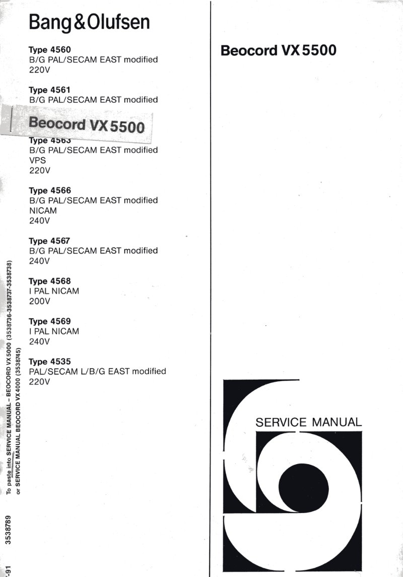
Beocord VX5500 Service Manual - Bang & Olufsen
Complete service manual for the Bang & Olufsen Beocord VX5500 tape recorder and associated models. This workshop documentation covers multiple variants including Type 4560, 4561, 4563, 4566, 4567, 4568, 4569, and 4535, with PAL/SECAM EAST and NICAM video standards across 200V, 220V, and 240V configurations. The manual provides detailed Hi-Fi audio system schematics and comprehensive electrical diagrams showing audio signal paths and component architecture. Includes Diagram J for the Type 456X series and Diagram K for Type 4535, with complete audio signal flow, component placement, and technical specifications. An essential repair and maintenance reference for technicians working on these premium audio-video recording systems, addressing tuner circuits, audio playback stages, microphone and headphone inputs, and control electronics for professional multi-format recording and playback. All wiring paths and circuit topology are documented for troubleshooting and component-level repair work.
Beogram 1800 Type 5811/13/14/15 Service Manual
Complete service and maintenance manual for the Bang & Olufsen Beogram 1800 record player, covering types 5811, 5813, 5814, and 5815. This workshop manual provides everything needed for troubleshooting and repair, with detailed circuit schematics, component layouts, and electrical diagrams throughout. You'll find comprehensive technical information on the turntable's motor control system, pickup arm assembly, and electronic control circuits, plus block diagrams showing how the power supply, amplifier sections, and mechanical control mechanisms interact. The manual includes timing diagrams and signal flow documentation essential for proper operation and diagnosis. A dedicated section covers fuse symbols and replacement specifications, noting the use of 500 milliampere 250 volt slow-acting fuses. Control signal timing information appears with waveform diagrams that illustrate the behavior of play, stop, cue functions, and automatic run-off stop sequences across different operational modes. Technical specifications and component references are integrated throughout to support repair and service work.