LUXMAN - Service Manuals
10 manuals available for download
Discover comprehensive technical documentation for LUXMAN audio and hifi equipment, including detailed service manuals, repair guides, and owner's manuals for classic amplifiers and preamplifiers. Our PDF download collection features workshop manuals, maintenance guides, and troubleshooting resources that enable both technicians and enthusiasts to understand, repair, and maintain LUXMAN components. Whether you need a parts list, schematic diagram, or complete user manual, find professional-grade documentation to support your audio equipment care and restoration projects.
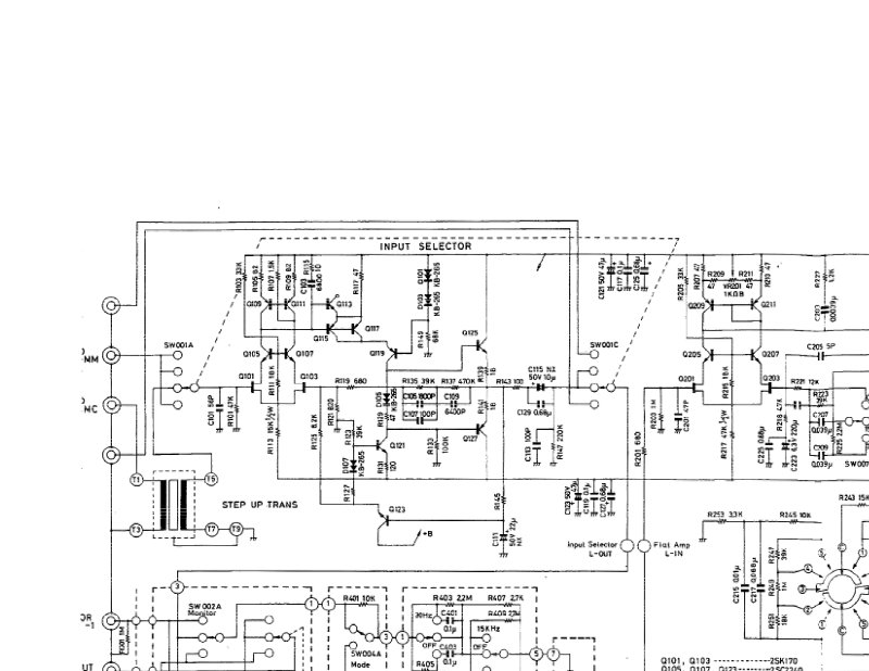
Luxman C-120A Stereo Preamplifier Schematic
Complete electronic schematic diagram for the Luxman C-120A stereo preamplifier. This single-page technical schematic provides detailed component layout, circuit connections, and precise part values—essential reference data for repair, maintenance, troubleshooting, component identification, and circuit analysis. Indispensable for anyone servicing or restoring the C-120A.
Luxman L-430/L-410 Amplifier Service Manual
Comprehensive service manual for Luxman L-430 and L-410 integrated amplifiers. Covers all essential repair and maintenance procedures including bias current adjustment techniques, complete exploded-view assembly diagrams, and full schematic diagrams with component placement guides for both models. Includes detailed parts lists for PCB assemblies PB-1408 and PB-1409 series, IC handling and installation guidelines, packaging specifications, and factory adjustment procedures. Essential reference for technicians performing routine maintenance, troubleshooting, or component-level repair work on these classic Luxman amplifiers.
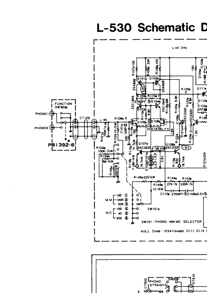
Luxman L-530 Schematic Diagram
Schematic diagram for the Luxman L-530 integrated amplifier. This two-page service document provides the complete electronic circuit layout with detailed component designations and printed circuit board references (PB1392-1 through PB1394-8), essential for understanding signal flow, troubleshooting, and component-level repair. Includes transistor specifications and interconnection details necessary for maintenance work on this classic amplifier.
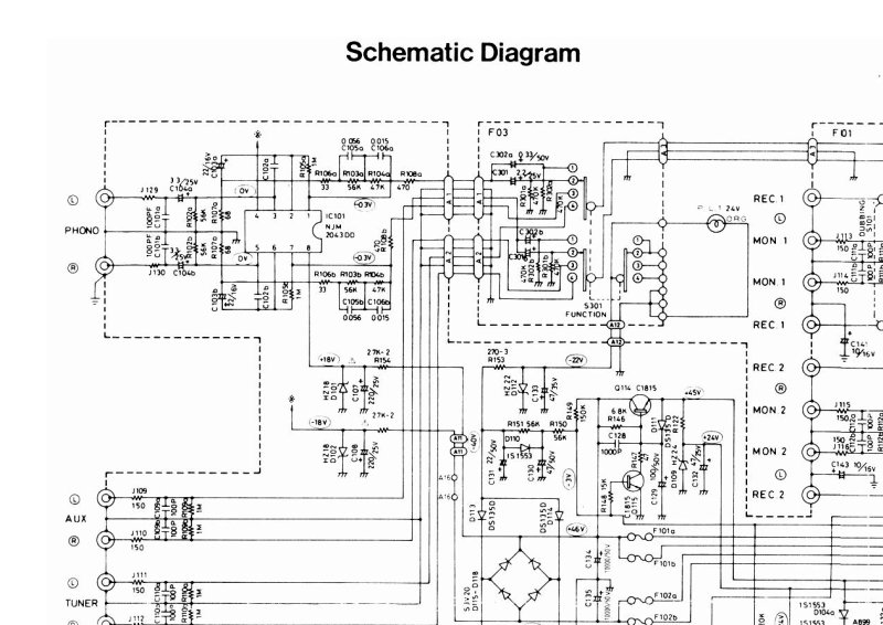
Luxman L210 Schematic Diagram
Schematic diagram for the Luxman L210 integrated amplifier. This detailed reference document covers the complete circuit architecture including the preamp input stage, power amplifier sections, tone control circuitry, and speaker output connections. Full component identification and electrical specifications are provided for troubleshooting, maintenance, and circuit analysis. Essential for any technician servicing this classic integrated amplifier.

Luxman L30 Solid State Integrated Amplifier Service Manual
Service manual for the Luxman L30 solid state integrated amplifier. This comprehensive workshop manual covers the complete circuit design and operation of the power supply, pre-amplifier, and main amplifier stages. Includes detailed idle current adjustment and zero DC offset calibration procedures essential for proper amplifier setup and performance. Features full schematic diagrams for the pre-amplifier board PB-1008 and power amplifier board PB-1009, allowing technicians to trace signal paths and diagnose circuit faults. Complete replacement parts lists itemize all resistors, capacitors, transistors, diodes, variable resistors, and coils needed for servicing and repairs. Exploded chassis assembly view aids in mechanical disassembly and reassembly. Indispensable reference for repair technicians and experienced hobbyists working on this classic solid state integrated amplifier.

Luxman L80 Service Manual
Complete service manual for the Luxman L80 integrated amplifier, providing detailed technical guidance for maintenance, troubleshooting, and repair work. This workshop manual covers the internal circuitry, component layout, and step-by-step procedures technicians need to service and restore this classic audio amplifier. Includes schematics, alignment procedures, and parts identification to support both routine maintenance and more involved repairs.
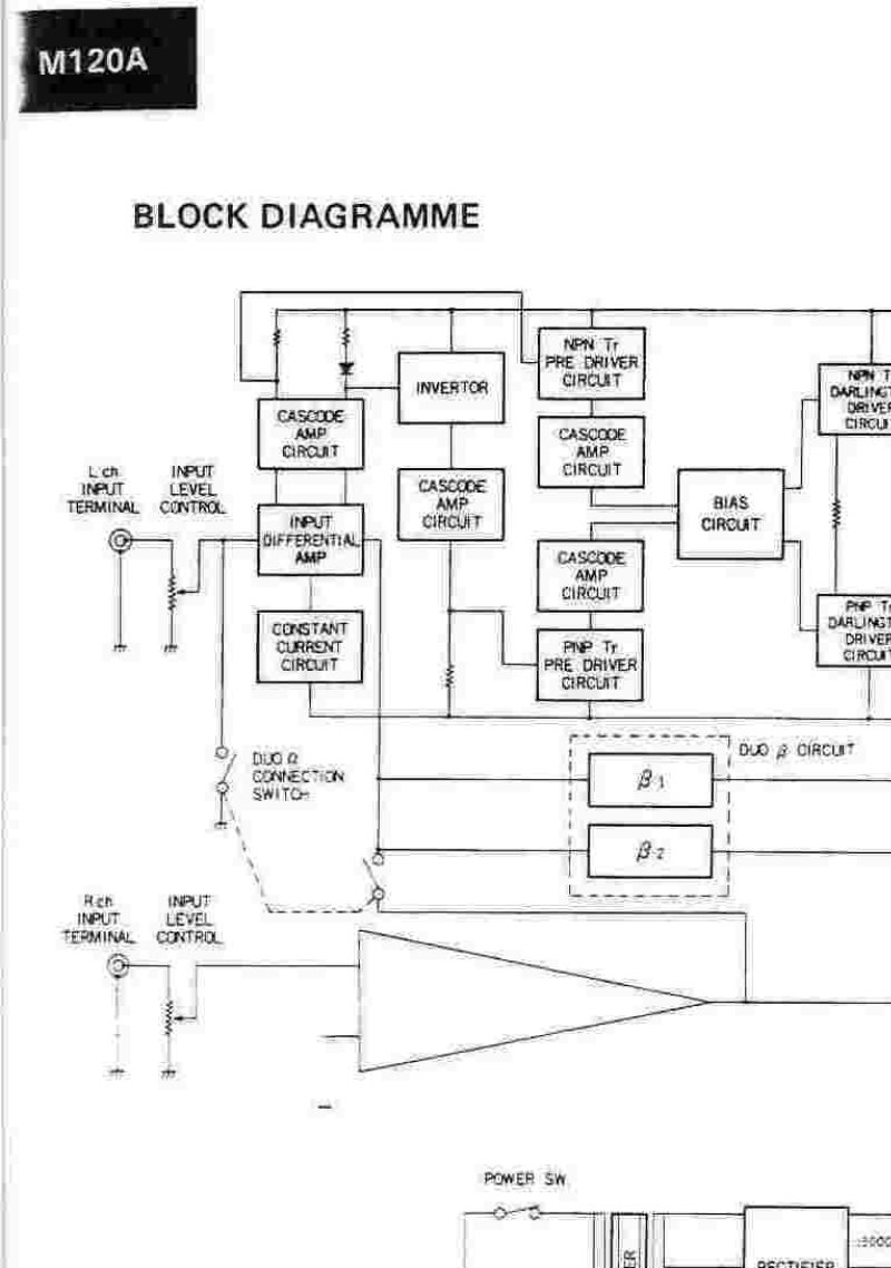
Luxman M120A Schematic Diagram and Specifications
Complete technical service documentation for the Luxman M120A stereo power amplifier, featuring detailed schematic diagrams and block circuit topology. The manual presents the full signal path from input stage through output stage, with transistor-level component identification throughout the power supply and amplification sections. Specifications confirm 120 watts minimum continuous power output per channel at 8 ohms impedance, 160K ohms input impedance, frequency response extending from 10Hz to 100kHz, and a damping factor of 50. Includes physical specifications for both wooden and metal cabinet enclosure options, along with weight data. Essential reference for repair technicians, maintenance work, and understanding the M120A's amplifier design and construction.
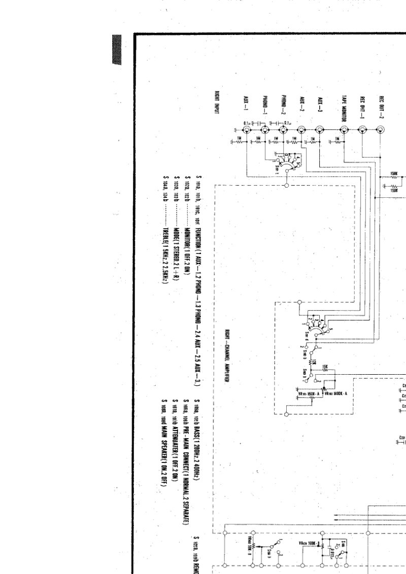
Luxman SQ503 Electronic Schematic Diagram
Complete electronic schematic diagram for the Luxman SQ503 amplifier. This documentation covers the full circuit layout with detailed component connections, signal paths, and power distribution architecture. Essential reference for troubleshooting, servicing, and understanding the amplifier's internal topology.
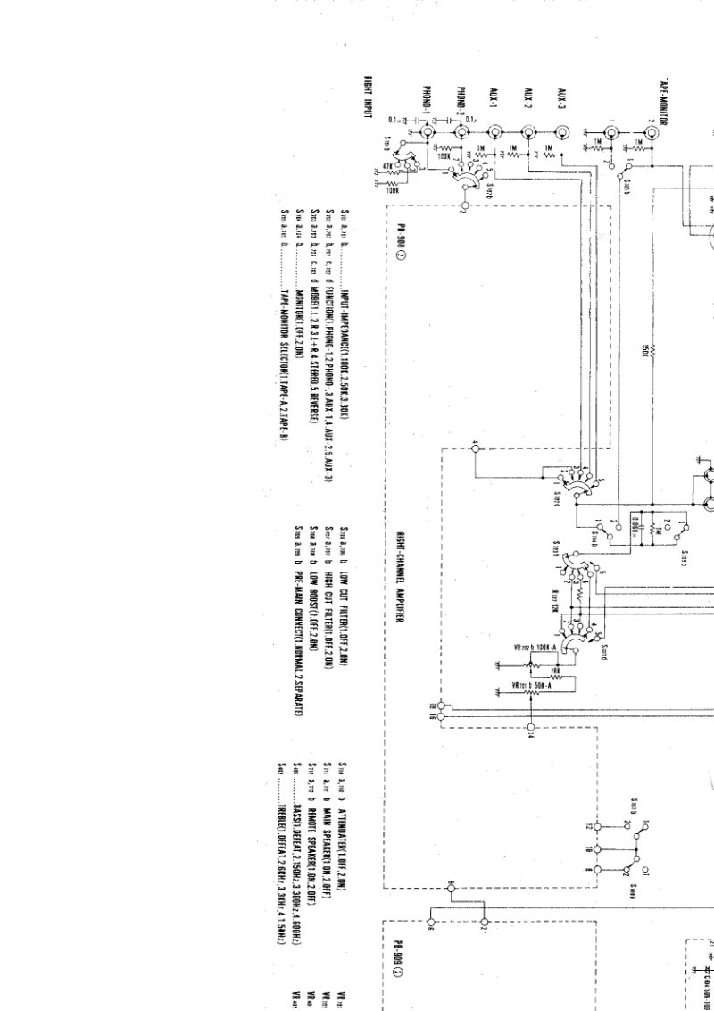
Luxman SQ505 Schematic Diagram 3
Electronic schematic diagram for the Luxman SQ505 integrated amplifier. This technical documentation provides detailed circuit diagrams with component layouts and signal paths for the tube and transistor-based circuitry. Essential reference material for technicians performing repairs, maintenance, or restoration work on this classic audio amplifier. Includes interconnection details and component placement information needed for troubleshooting and service procedures.
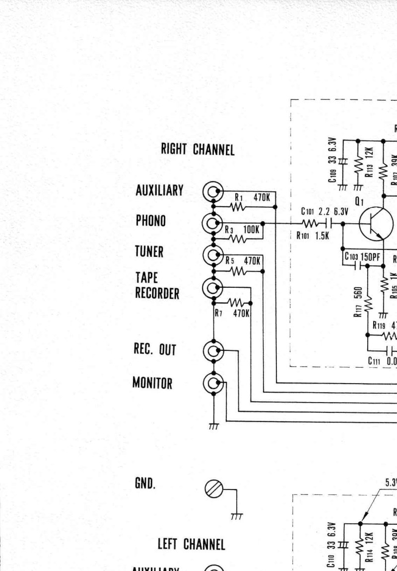
Luxman SQ707 Schematic Diagram
Complete schematic diagram for the Luxman SQ707 integrated amplifier, essential for service and repair work on this classic audio component. The diagram details both left and right channel circuits, mapping out the input stage, pre-amplifier, tone control circuitry, and power amplifier sections with full component identification. Includes precise resistor and capacitor values throughout, transistor specifications (2SC693GU, 2SC694G, 2SC734Y, 2SC815L, 2SA545, 2SC853, 2SD92), and the power supply circuit featuring a 50–60 Hz transformer rated at 90W maximum output. Shows the dual speaker configuration (A-Speaker and B-Speaker selection) and headphone output path, making this schematic indispensable for troubleshooting, alignment, bias adjustment, and component-level repair of the SQ707.