KEARNEY & TRECKER - Service Manuals
171 manuals available for download
KEARNEY & TRECKER stands as a respected manufacturer of precision milling machines, and our comprehensive collection of technical documentation supports owners and technicians in maximizing equipment performance. Whether you need a detailed service manual, repair guide, troubleshooting documentation, or complete parts lists, our PDF downloads provide the essential information required for maintenance, workshop operations, and long-term machine care. Access authentic owner's manuals and maintenance guides designed to keep your KEARNEY & TRECKER equipment running efficiently and reliably.
1200-1800 Series Bed Type Milling Machine Parts List
Replacement parts manual for Kearney & Trecker Milwaukee 1200-1800 Series simplex and duplex bed type milling machines. Catalog BR-10 includes indexed parts list, assembly unit diagrams, and dimensional drawings. Contains 23 unit assembly sections covering bed parts, gear boxes, spindle components, saddle, table, and drive components with part numbers and reference pages.
1200-1800 Series Milling Machines Operator's Manual
Operator's manual for Kearney & Trecker Milwaukee 1200-1800 Series Simplex and Duplex bed type milling machines. Covers operation, lubrication, adjustment, uncrating, shortages checking, hoisting procedures, machine placement on solid foundation, and leveling instructions for both Simplex and Duplex models.
1200-1800 Series Replacement Parts Manual
Replacement parts catalog for Kearney & Trecker Milwaukee 1200-1800 Series Simplex and Duplex bed type milling machines. Contains unit assembly numbers, part index, and unit assembly drawings. Includes sections on machine photos (left and right front views), plan dimensions, bed parts, speed change gear box, feed change gear box, arm pendants and braces, spindle drive gear box, control valve assemblies, spindle blocks, table, drive brackets, saddles, feed worm assemblies, hand control bracket, and drive pulley bracket.
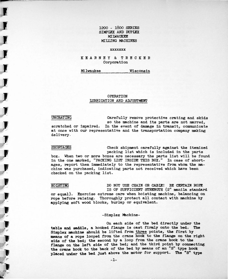
1200-1800 Simplex/Duplex Milling Machine Manual
Operator's manual for Kearney & Trecker Milwaukee 1200-1800 Series Simplex and Duplex bed type milling machines. Covers uncrating, shortages verification, hoisting procedures with three-point rigging for Simplex and two-point for Duplex models, foundation preparation, leveling procedures using different guide points for each machine type, and initial setup instructions.
1H-2HL Knee Type Milling Machine Parts List
Replacement parts manual for the Kearney & Trecker 3hp Model H and Model HL plain-universal-swivel head vertical knee type milling machines (PUB 90, formerly HR-21). Contains exploded assembly views with numbered components, parts identification instructions, and ordering procedures. Includes detailed guidance on identifying desired parts through assembly diagrams on pages 4-5, locating item numbers, and contacting the service department with machine specifications.
1H-2HL Knee Type Milling Machines Parts Manual
Replacement parts manual for Kearney & Trecker Model H and Model HL knee-type vertical milling machines. Covers 3hp No. 1 Model H and 3hp No. 2 Model HL with plain, universal, and swivel head configurations. Includes indexed visual assembly diagrams and parts lists. Published 1952.
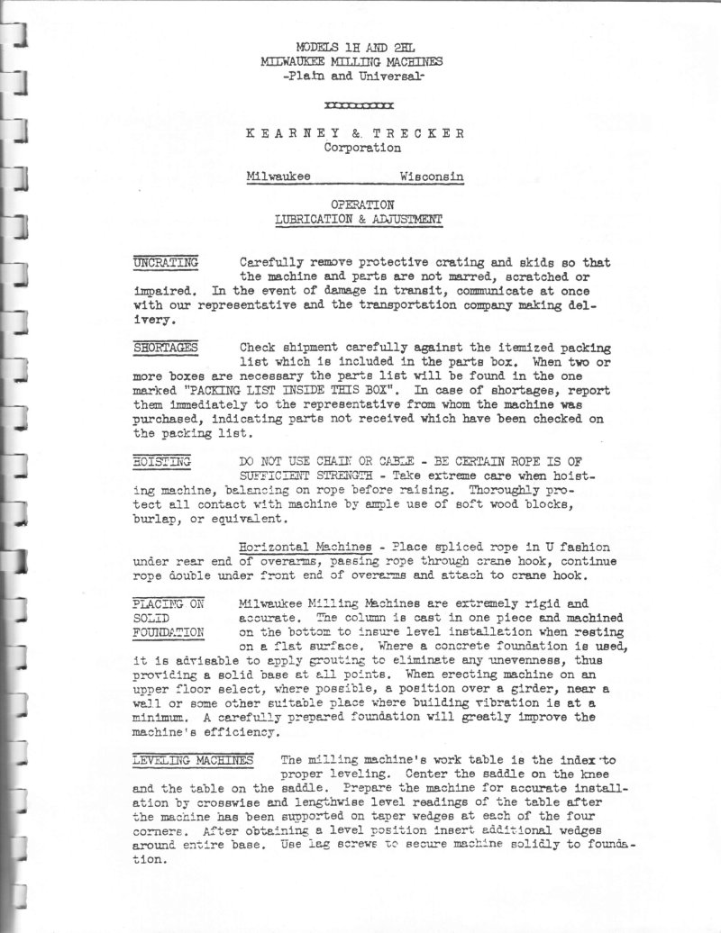
1H-2HL Milling Machine Operation Manual
Operation, lubrication and adjustment manual for Kearney & Trecker Models 1H and 2HL Milwaukee milling machines. Covers uncrating and handling, machine placement and leveling on solid foundation, lubrication procedures including column lubrication, knee lubrication, saddle lubrication, and overarms. Details motor installation, V-belt alignment and tension, pulley speed settings with RPM and rotation direction indicators, and daily maintenance procedures. Includes instructions for cleaning and flushing lubricant reservoirs at four-month intervals.
1H-2HL Milling Machine Replacement Parts Manual
Replacement parts manual for Kearney & Trecker 3hp Model H and Model HL Plain, Universal and Swivel Head Vertical milling machines. Catalog No. HR-21, Publication No. 90. Includes instructions for identifying and ordering replacement parts. Document emphasizes that certain parts are mated at factory and cannot be replaced individually but must be ordered in pairs or sets. Serial number identification information required for all inquiries. Contains indexed visual assembly arrangements on pages 4-5.
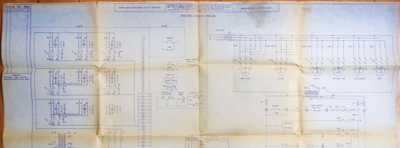
2D Rotary Head Milling Machine Schematic
Wiring diagram and schematic for a 2D rotary head milling machine with power feed knee. Single page containing electrical circuit diagrams with motor controls (spindle motor, knife motor, table motor, rotary HD motor, coolant motor, air motor), isolator switch, reset circuits, lighting circuits, and a detailed pin configuration table.
2K & 3K Vertical Milling Machine Parts List
Repair parts book for Milwaukée Models 2K and 3K vertical milling machines. Contains unit assembly line drawings with part numbers and a comprehensive list of repair parts organized by assembly number (2791-2849). Includes reference to serial number location on machine column for correct part identification. Published by Kearney & Trecker Corporation.
2K and 3K Milling Machines Operator's Manual
Operator's manual for Kearney & Trecker Models 2K (7.5 hp) and 3K (10 hp) plain, universal, and vertical milling machines. Covers operation, lubrication, adjustment, uncrating, shortage checks, hoisting procedures, cleaning, lacing, and foundation requirements. Document reference PUB 94 (KC11) dated March 1978.
2K-3K Milling Machines Replacement Parts List
Replacement parts manual for Kearney & Trecker Model 2K and 3K Plain, Universal and Vertical knee type milling machines. 7.5 hp Model No. 2 and 10 hp Model No. 3 machines with mono-lever and automatic cycle table control or standard directional table control. Contains exploded assembly views with numbered parts, identification instructions, and ordering procedures. Published July 1977, formerly publication No. KR-20.
3CH-4CH Milling Machines Parts Manual
Replacement parts manual for Kearney & Trecker plain, universal and vertical milling machines. Covers models 3CH, 4CH, 210CH, 310CH, 315CH, 415CH and their numbered variants (210CH-14, 310CH-14, 315CH-16, 415CH-16). Publication No. 54. Table of Contents: - Oil Filler Cap - Oil Screw - Column - Vent Plate - Screw - Door Assembly - Gasket - Connector Plate - Screw - Corner Bracket - Plug - Screw - Door Latch Strip - Junction Box Cover - Gasket - Screw - Coolant Pump Wiring Chamber Cover - Gasket - Screw - Screw - Drain Screen Cover Knob - Drain Screen Cover - Drain Screen - Screw - Stop Pin - Stop Pin - Nipple - Pipe Cap - Switch Housing - Screw - Screw - Switch Bracket - Screw - Coolant Cleanout Cover - Screw - Expansion Plug - Modular Swivel - Set Screw - V-Pulley - Stop Pin - Pendant Arm - Pendant Rear Cover - Gasket - Pendant Body - Pendant Front Cover - Screw - Stud - Oil Flow Gage - Oil Level Gage - Motor Door Assembly - Motor - Drive Belt - Set Screw - Motor Sheave - Motor Fan - Dowel - Screw - Motor Base Support Pin - Motor Base - Set Screw - Nut - Cap Screw - Nut - Cap Screw - Trip Dog, Lower - Trip Dog, Upper - Nut - T Bolt - Overarm Handwheel - Pin - Pinion Shaft - Pin, Outer - Pin, Inner - Set Screw - Overarm Pinion - Expansion Plug - Screw - Plug - Washer - Spindle Head - Gasket - Filter - Ball Retainer - Screw - Nut - Washer - Overarm Clamp - Spring - Pin
5H Vertical Milling Machine Parts List
Replacement parts manual for the Kearney & Trecker Milwaukee 5H Vertical knee type milling machine. Catalog HR-18 contains indexed parts list with unit assembly numbers and part names. Covers components including adjustable vertical heads, vertical column, coolant pump, feed brackets, gear trains, speed gear boxes, and control mechanisms. Contains assembly drawings and part identification reference.
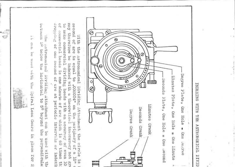
Astronomical Dividing Head Technical Data
Technical documentation for an astronomical dividing head, featuring detailed mechanical drawings showing a circular attachment with concentric discs and indexing mechanism. Includes engineering specifications with formula for calculating divisions: 1,296,000/N = S + R or (S+1) - (N-R)*. Example calculation provided for 119 divisions with compensation methods using degree, minute, and seconds plates. Contains adjustment procedures for accurate indexing across multiple divisions.
CNC Part Programming Pre-School Visuals
Audio/visual learning system PUB 739 from Kearney & Trecker Corporation. First Edition May 1979. Contains programmer prerequisites including reading part prints, visualizing parts in three dimensions, machining operation experience, systematic thinking, and mathematics knowledge. Document includes visual training materials for CNC part programming pre-school instruction.
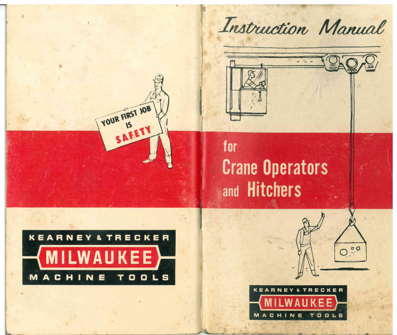
Crane Operators and Hitchers Instruction Manual
Safety instruction manual for crane operators and hitchers published by Kearney & Trecker Milwaukee Machine Tools. The manual emphasizes that safety is the first job priority. Contents include foreword explaining the crane operator and hitcher roles compared to railway crew, and detailed instructions for crane operators covering authorization requirements, visibility advantages, unsafe condition protocols, joint responsibility for safe lifts, load carrying restrictions over aisles with bell signals, and restrictions on carrying loads at eye level.
CSM Milling Machines Parts Manual
Replacement parts manual for Kearney & Trecker Model CSM plain and vertical milling machines, 20hp Nos. 2 and 3, 30hp Nos. 3 and 4. Covers both standard directional table control and mono-lever with automatic cycle table control variants. Includes photographic views of vertical and plain machine configurations.
CSM, CK & CH Milling Machines Installation Manual
Installation manual for Kearney & Trecker Milwaukee milling machines covering Models CK (10hp No. 2 and 15hp No. 3) and CH (7.5hp No. 3 and 10hp No. 4), as well as CSM (20hp Nos. 2-3 and 30hp Nos. 3-4). Includes instructions for uncrating, inspection for shortages, hoisting procedures for both horizontal and vertical machines, and location/installation guidance with weight specifications and securing methods.
CSM, CK and CH Milling Machines Operator's Manual
Operator's manual for Kearney & Trecker plain, universal and vertical milling machines. Covers models CSM (20hp Nos. 2 and 3, 30hp Nos. 3 and 4), CK (10hp No. 2 and 15hp No. 3), and CH (7.5hp No. 3 and 10hp No. 4). Includes sections on electrical system, lubrication system, coolant system, conventional operation controls, automatic cycle operation with mono-lever and standard directional table control, speed and feed charts, and arbor support instructions.
Data-Mill 700 Operating Manual
Part programming and operating manual for the Data-Mill 700 horizontal and vertical CNC machine tools equipped with KT/CNC pendant mounted operator's panel. Published by Kearney & Trecker Corporation. Includes safety guidelines and operational procedures. Table of Contents: - Coordinate System - Axes Travel Limits - Zero Reference Positions - Standard Grid - Collisions Zones - Table Description - Spindle Head Unit Description - Spindle Horsepower - Spindle Speeds - Spindle Configuration - Power Draw Bar - Spindle Overload Protection - Coordinate System - Axes Travel Limits - Zero Reference Positions - Standard Grid - Collisions Zones - Table Description - Spindle Head Unit Description - Spindle Horsepower - Spindle Speeds - Spindle Configuration - Power Draw Bar - Spindle Overload Protection - Program - Process Planning Sheet - Block Unit Input - Letter Address System - Positioning Mode (G00) - Continuous Mode (G01) - Absolute Mode (G90—Linear & Rotary) - Incremental Mode (G91—Linear & Rotary)
Data-Mill 700 Programming and Operating Manual
Part programming and operating manual (PUB 6884C) for Data-Mill 700 horizontal and vertical machines equipped with Kearney & Trecker manual data input control. Includes safety guidelines (PUB-578) emphasizing safe machine operation practices. Document addresses all occupation skill groups involved in machine operation, supervision and maintenance. Table of Contents: - Control Description - Standard Control Features - Pushbutton and Selector Group - E-Stop/Spindle Reset Pushbutton - Emergency Stop Pushbutton - Inch/Metric Selector Switch - Clear All Pushbutton - Percent Spindle Speed Selector - Mode Select Selector Switch - Display Select Pushbutton - Offset Pushbutton - Grid Pushbutton - Alpha Numeric Display and Keyboard Group - Event Enter Key - Return Key - Cursor Key - Event Search Key - Event Num Key - Clear Key - Prog Tab Key - Sub Ret Key - Aux Function Key - Wait/Turn Key - Prep Code Key - CCW Key (Counterclockwise) - CW Key (Clockwise) - Cool Key - Blank Key - Go To Sub Key - Off Key - On Key - Feed Key - Rapid - Dwell Key - Blend Key - INCR Key (Incremental) - ABS Key (Absolute) - Prog Stop Key - Right Key - I-Table Key - K-Cross Key - J-Vert Key - Rtry Key (Rotary Axes Option) - Shift Key - Diam Key (Tool Diameter Compensation)
Econumeric Precision Tool Setter Manual
Tool setting manual and parts list for Econumeric Precision Tool Setter by Kearney & Trecker Corporation. Publication PUB.102 from February 1978. Includes safety guidelines (PUB-578, First Edition May 1976) emphasizing safe machine tool operation and maintenance procedures for all occupational skill groups.
Fixture Design Service Manual for KT/NC
Sixth edition fixture design manual from April 1977 for Kearney & Trecker Milwaukee-Matic machine tools. Chapter 1 covers basic fixturing concepts including fundamental principles of geometric location (three points determine a plane, additional points establish transverse location, etc.). Includes technical illustrations demonstrating spherical objects on three points and flat planes with multiple locating points.
General Tolerances - Technical Data
Technical data and reference guide for general dimensional and geometrical tolerances published by Kearney & Trecker Corporation. Revised edition from July 1978 (Pub. 417A). Covers definitions and significance of terms associated with acceptable variations in engineering drawings including dimensions, angles, alignment, geometric elements, casting and machining tolerances, and surface specifications. Intended to ensure proper interpretation of engineering drawings and manufacturing specifications. Table of Contents: - Acme Screw Threads - Alignment - Hole to Hole - Keyways - Slots - Surface to Surface - Angles - Basic Dimensions - Bends, Sheet Metal Squareness - Blocks, Title - Bores, Oil Seal - Breaks, Edge - Broached Holes - Casting Tolerances - Chamfers - Clearance, Depth Tap Drill - Combination of Geometric Elements - Concentricity - Face Runout - Hole to Hole - Surface to Hole - Surface to Surface - Squareness of Face - Corner, Sharp - Countersinks - Cylindrical Surface Straightness - Depth, Drilled Hole Tolerances - Dimensions - Decimal, Unitoleanced - Drawing - Fractional - Limiting - Max.-Min. - Out of Scale - Reference - Typical - Dowel Pin Holes - Drawings, Fractional Format - Drawings, General Tolerances - Drawing Title Blocks - Drill Depth, Tap - Drilled Holes - Drilled Hole Tolerances - Drills, Tap Pipe Thread - Drills, Tap Vee Thread - Dryseal Pipe Threads - Edge Breaks - Effective Length - Elements, Geometric Combination - External Threads - Face Runout - Face Squareness - Feature Relationships - Finish Dimensions - Finish Marks - Flatness - Machined Surfaces - Sheet Metal Parts - Fractional Dimensions - Fractional Format Drawings - Fractional Drawing Title Blocks - General Drawing Tolerance - Geometric Standards - Geometric Tolerances - Alignment of Holes - Alignment of Keyways - Alignment of Surfaces - Combination of Elements - Concentricity, Holes - Concentricity, Shafts - Face Runout - Face Squareness - Flatness, Plane Surface - Flatness, Sheet Metal - Out of Round - Parallelism, Holes - Parallelism, Hole to Surface - Parallelism, Plane Surface - Perpendicularity, Hole to Surface - Perpendicularity, Projection - Roundness - Slot Symmetry - Squareness, Hole System - Squareness, Plane Surfaces - Squareness, Sheet Metal Parts - Straightness, Cylindrical Parts - Straightness, Plane Surfaces - Symbols - Grind Marks - Ground Holes
HB-4 with KT-Gemini-E Programming Manual
Programming and operating manual supplement (PUB 821) for the Milwaukee HB-4 metal cutting machine with KT-Gemini-E machine control system. Includes safety guidelines emphasizing that safety is everybody's business, with reference to supplementary safety literature (PUB-578). Published by Kearney & Trecker Corporation.
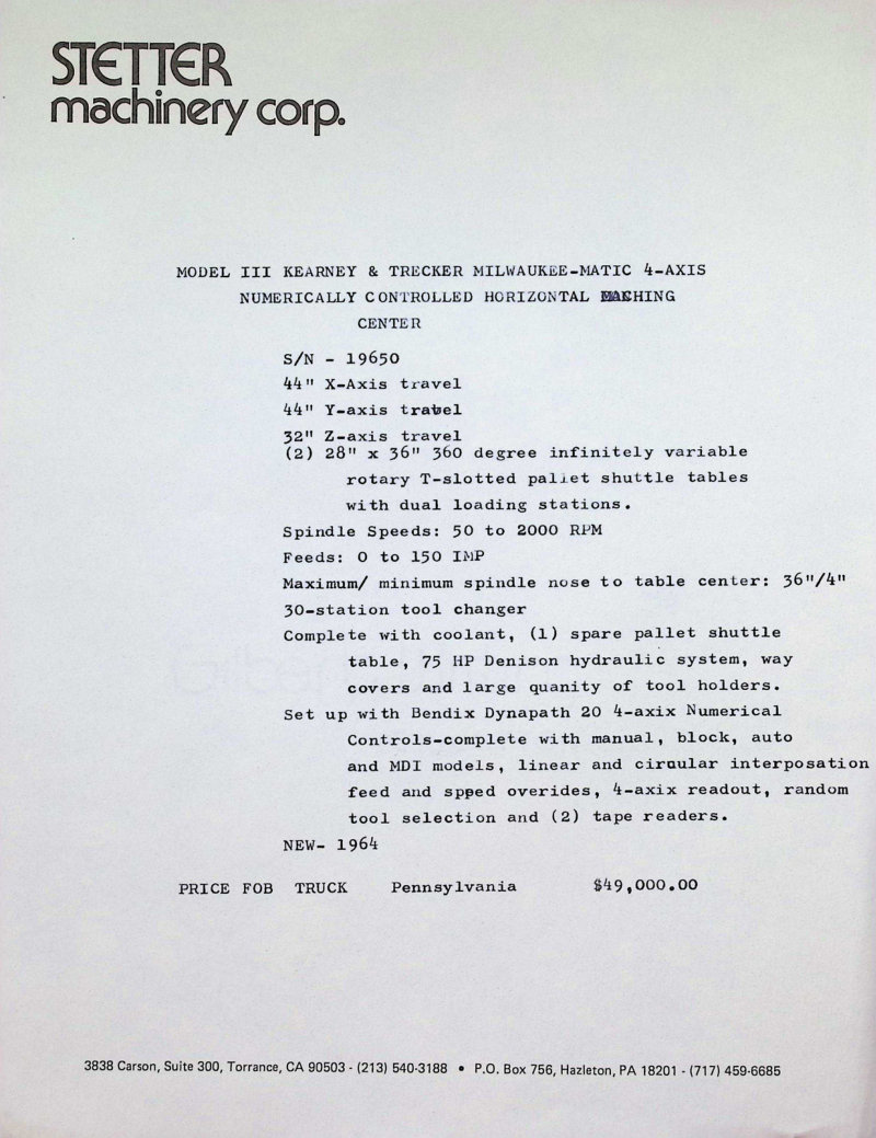
K&T Model III & Vertical Mill Technical Data
Technical proposal and specifications document for two used machine tools: a Kearney & Trecker Model III Milwaukee-Matic 4-axis numerically controlled horizontal machining center (S/N 19650, new 1964) with 44 inches X-axis travel, 44 inches Y-axis travel, 32 inches Z-axis travel, (2) 28 inches by 36 inches 560-degree infinitely variable rotary T-slotted pallet shuttle tables, spindle speeds 50-2000 RPM, feeds 0-150 IMP, 30-station tool changer, 75 HP Denison hydraulic system, Bendix Dynapath 20 4-axis numerical controls; and a used Kearney & Trecker Model #205 S12 vertical mill with oversize table (No. 50 NT, 12 inches by 62.5 inches table working surface, 34 inches longitudinal feed, 12 inches cross feed, 18 inches vertical travel A, 9 inches vertical head travel with hand or power, 24 spindle speeds 20-1600 RPM, feeds 1/4 to 32 inches per minute, serial No. 29/9463, 1964, equipped with DBL-104 criterion boring head, position stop with dial micrometer, back lash eliminator, milling vise, coolant system, 5 HP main spindle motor 220/440/3/60, weight 6150 lbs). Proposal dated November 19, 1980 from Ball Machinery Company, Chicago. Price FOB truck Pennsylvania 49,000.00 dollars for Model III; Model 205 S12 priced at 24,500.00 dollars less 10 percent discount.
Kearney & Trecker Handling of Parts Guide
Kearney & Trecker Milwaukee Machine Tools quality guide on proper handling of parts and materials. Covers material handling responsibilities, packing methods, and specific handling techniques including stick protection with plastic tubing to prevent rust transfer and part nicking. Features practical examples and workmanship standards to ensure quality throughout the manufacturing process.
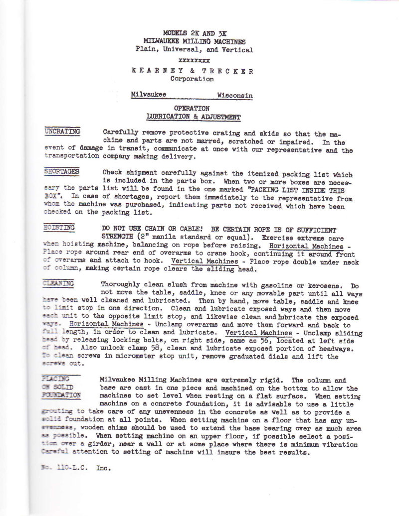
Kearney & Trecker Model K Operator's Manual
Operator's manual for Kearney & Trecker Model K plain, universal, and vertical milling machines (7.5 hp No. 2 and 10 hp No. 3 models). Contains instructions for uncrating, assembly, lubrication, adjustment, motor installation, belt drive setup, leveling, and column lubrication procedures. Includes detailed setup guidance for proper operation and maintenance.
Kearney Trecker AR-20 Replacement Parts Manual
Replacement parts manual for Kearney & Trecker Milwaukee thread milling, rack milling, rack indexing and slotting attachments for milling machines. Includes exploded views and part identification instructions with ordering information. Published 1956.
Knee Milling Machine Replacement Parts Manual
Replacement parts manual for automatic cycle plain, universal and vertical knee type milling machines. Published by Kearney & Trecker Corporation in November 1977. Publication PUB 91 (HR-23). Document includes safety guidelines (PUB-578) emphasizing that safety is everybody's business.
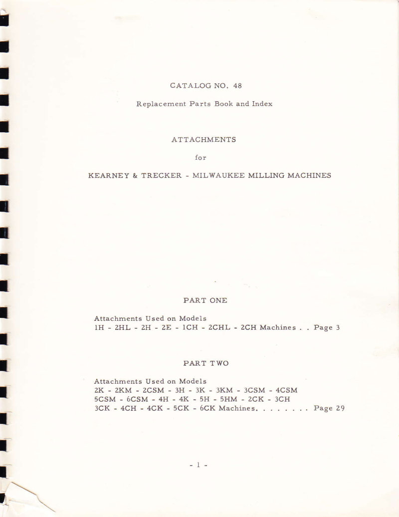
Knee Type Milling Machines Attachments Parts List
Catalog No. 48 - Replacement parts book and index for Kearney & Trecker Milwaukee milling machine attachments. Part One covers models 1H, 2HL, 2H, 2E, 1CH, 2CHL, 2CH. Includes 12 inches rotary table, rotary table drive bracket, heavy duty vertical milling attachment, 16 and 20 inches rotary tables, right angle drive bracket, rack indexing attachment, thread milling attachment, crane attachment, light high speed universal milling attachment, standard adjustable universal head attachment, heavy duty universal milling attachment, slotting attachment, rack milling attachment, and dividing head attachments. Part Two covers models 2K, 2KM, 2CSM, 3H, 3K, 3KM, 3CSM, 4CSM, 5CSM, 6CSM, 4H, 4K, 5H, 5HM, 2CK, 3CH, 3CK, 4CH, 4CK, 5CK, 6CK. Table of Contents: - Catalog No. 48 - Replacement Parts Book and Index - Attachments for Kearney & Trecker - Milwaukee Milling Machines - Part One - Attachments Used on Models 1H - 2HL - 2H - 2E - 1CH - 2CHL - 2CH Machines, Page 3 - Part Two - Attachments Used on Models 2K - 2KM - 2CSM - 3H - 3K - 3KM - 3CSM - 4CSM - 5CSM - 6CSM - 4H - 4K - 5H - 5HM - 2CK - 3CH - 3CK - 4CH - 4CK - 5CK - 6CK Machines, Page 29
KR-10 Replacement Parts Manual 2K 3K
Replacement parts catalog for Milwaukee Milling Machines Models 2K and 3K (Plain, Universal, and Vertical). Includes indexed parts list with assembly drawings, part numbers, and component identification for arm braces, feed systems, drive brackets, gear boxes, spindle heads, and machine accessories. Published by Kearney and Trecker Corporation. Table of Contents: - Arm Brace & Arbor Support - Starting Lever - Column - Column - Speed Gear Box - Pulley Bracket - Feed Gear Train - Feed Gear Train - Knee Table & Saddle - Elevating Screw Assembly - Feed & Rapid Traverse Drive Bracket - Feed & Rapid Traverse Drive Bracket - Feed Distribution Box - Feed Distribution Box - Coolant Pump - Cross Feed Bracket - Coolant Return - Universal Saddle Block & Table - Universal Swivel Block & Table - Tail Stock - Saddle Table - Plain Saddle & Table - Control Bracket - Rear Control Bracket - Speed Gear Box - Speed Gear Box - Speed Gear Box - Speed Gear Box - Feed & Rapid Traverse Take-Off Bracket - Feed & Rapid Traverse Take-Off Bracket - Feed & Rapid Traverse Take-Off Bracket - Feed Distribution Box - Conventional Change Gear Box - Spiral Change Gear Box - Spiral Change Gear Box - Spiral Change Gear Box - Trip Blocks for Spiral Change Gear Box - Spiral Dividing Head - Spiral Dividing Head - Spiral Dividing Head
KT Cellular System Level I Control Manual
Control maintenance manual for the KT Cellular System Level I Control (PUB 941). Includes safety guidelines emphasizing that safety is everybody's business. Document addresses maintenance procedures for metal cutting machine tools and operational safety precautions for machine operators, supervisors, maintenance technicians, and observers. First edition from May 1976. Table of Contents: - The employer is responsible for selecting competent and qualified employees - Manuals are provided with each machine tool - Guards and shields are to be in place at all times - Operators must be forbidden from changing workpieces or performing other work close to a revolving cutter - When contaminants are released to the atmosphere as a result of machining, an exhaust system is recommended - All employees should be aware of first aid facilities and be encouraged to use same - Employees should be encouraged to report any hazardous condition on the machine tool or in the immediate area - Air hoses — it is recommended that air hoses not be available for use around the machine tool - Levels of illumination in the immediate area of the machine tool should comply with National Standards - Fire prevention must be practiced and fire protection available to prevent loss of life, personal injury and to protect property - Protective footwear — safety shoes afford good protection against rolling objects, dropping heavy objects, accidentally kicking sharp edged materials - Eye protection — eye protection devices must be considered as optical instruments and they should be carefully selected, fitted and used - The employer must insist that his employees study this safety information and practice safety - Users must have available adequate lifting facilities capable of lifting within the safe load limits - Every floor opening resulting from the machine tool installed in pits or below floor level should be covered with a material of proper strength with non-slip features - When machines are installed above floor level and a platform is built around the machine tool, the platform must be constructed of materials of proper strength with non-slip features - Management personnel have the responsibility to alert operating personnel of any unsafe practice they may observe
KT-APL Programming Manual for KT-GEMINI-D
Part programming manual (PUB 929A) for the Advanced Programming Language (KT-APL) used with the KT-GEMINI-D machine control system by Kearney & Trecker Corporation. Includes safety guidelines and part programming instructions. 265 pages total. Table of Contents: - Introduction - KT-GEMINI-D Control System - Programming Features - Operating Features - Machine Programming Language - Preliminary Forms & Drawings - Pallet Mapping - Part Program Preparation - Block Unit Input - Letter Address System - Letter Addresses & Functions - Axis Related Commands - Axis Departure (Linear Axes) - Axis Departure (Rotary Axes) - Axis Departure (Indexing B Axis) - Arc Center - Fixed Cycle Clearance Plane (R-Word) (Modal) - Fixed Cycle Incremental Feed Distance (E-Word) (Modal) - Offset Related Commands - Fixture Offset Compensation - Program Organization Commands - Preparatory Function - Miscellaneous Function - Sequence Number (N-Word) - Feedrate Number (F-Word) (Modal) - The P0 Command - Spindle Programming (S-Word) (Modal) - Tool Select (T-Word) - Type II Data Statements - General Information - G00 Positioning Mode (MS) - G01 Continuous Mode (M) - G02 Circular Interpolation Clockwise (NM) - G03 Circular Interpolation Counterclockwise (NM) - G04 Programmable Dwell (NM) - G17 XY Plane Selection for Circular Interpolation (MS) - G13 XZ Plane Selection for Circular Interpolation (M) - G19 YZ Plane Selection for Circular Interpolation (M) - G20 and G21 Axis Substitution - G22-G37, G60-G62, G92 Spindle Probe Cycles - G22 Record Axis Position "Contact" (NM) - G23 Record Axis Position "Non-Contacts" (NM) - G24 Tolerance Verification (NM) - G25 Automatic Regrid (NM)
KT-Gemini Adaptive Control Programming Manual
Part Programming/Operating Manual Supplement (PUB 850A) for Adaptive Control systems on KT-Gemini machine control systems. Includes safety guidelines and operational procedures for metal cutting machine tools. First edition, May 1978. Table of Contents: - Employer responsibility for selecting competent and qualified employees - Manuals provided with each machine tool - Guards and shields in place at all times - Operators forbidden from changing workpieces near revolving cutter - Exhaust system recommended when contaminants released - First aid facilities awareness and use - Employees encouraged to report hazardous conditions - Air hoses not available for use around machine tool - Illumination levels comply with National Standards - Fire prevention and protection practices - Protective footwear and safety shoes - Eye protection devices - Employer must insist employees study safety information - Adequate lifting facilities with safe load limits - Floor openings covered with proper strength material - Machines installed above floor level with platform safety features - Management responsibility to alert personnel of unsafe practices
KT-Gemini-D Machine Control Operating Manual
Operating manual for the KT-Gemini-D Machine Control System by Kearney & Trecker Corporation. Document PUB 865 includes safety guidelines (PUB-578, First Edition May 1976) emphasizing safe machine tool operation across all occupation skill groups. Contains preface and safety information for metal cutting machine tools. Table of Contents: - Chapter 1 - KT-Gemini-D Machine Control System Description - Control Description - PDP Door - MCU Door - Back of KT-Gemini-D MCS - Air Cooling Unit - Memory Backup System - Modes of Operation - [AUTO] - Auto Mode - [Single Block] - Single Block Mode - [MAN] - Manual Mode - [MDI] - Manual Data Input Mode - [TEST] - Test Mode - Test Run - Dry Run - Fast Run - [Program Retrace] - Program Retrace Mode - Chapter 2 - Operators Control Panel - Operator's Control Panel - Status Light Group - Power Fault - Control Fault - Over Temperature - Memory Backup Fault - Emergency Stop - Inch - Metric - Axis Invert - Axis Offset - Jog Active - Adaptive Control On - Probe Contact - Spindle Enabled - Remote Transmission - Spare Indicators - Control Group - Clear Active Block - Clear Ready Block - Clear All Logic - Remote Panel Active - Grid Axis - Move to Reference - Function 1 - Error Recovery - Function 2 - Help - Program Group
KT-Gemini-D Programming Manual PUB 841
Universal part programming manual for the KT-Gemini-D machine control system by Kearney & Trecker Corporation. Includes safety guidelines and operational procedures for metal cutting machine tools. First safety section (PUB-578) addresses safety practices for all occupational skill groups involved in machine operation, supervision and maintenance. Table of Contents: - KT GEMINI D-17 CONTROL SYSTEM - MACHINE PROGRAMMING LANGUAGE - PRELIMINARY FORMS AND DRAWINGS - PART PROGRAM PREPARATION - BLOCK UNIT INPUT - LETTER ADDRESS SYSTEM - LETTER ADDRESSES AND FUNCTIONS - AXIS RELATED COMMANDS - Axis Departure (Linear Axes) - Axis Departure (Rotary Axes) - Axis Departure (Indexing B Axis) - Arc Center Offsets - Fixed Cycle Clearance Plane (R-Word) - Fixed Cycle Incremental Feed Distance (E-Word) - OFFSET RELATED COMMANDS - Tool Length Compensation - Cutter Diameter Compensation - Fixture Offset Compensation - PROGRAM ORGANIZATION COMMANDS - Preparatory Function - Miscellaneous Function - Sequence Number (N-Word) - Feedrate Number (F-Word) - Spindle Programming (S-Word) - Tool Select (T-Word) - TYPE II DATA STATEMENTS - GENERAL INFORMATION - G00 POSITIONING MODE - G01 CONTINUOUS MODE - G02 CIRCULAR INTERPOLATION CLOCKWISE - G03 CIRCULAR INTERPOLATION COUNTERCLOCKWISE - G04 PROGRAMMABLE DWELL - G17 XY PLANE SELECTION FOR CIRCULAR INTERPOLATION - G18 XZ PLANE SELECTION FOR CIRCULAR INTERPOLATION - G19 YZ PLANE SELECTION FOR CIRCULAR INTERPOLATION - G25-G37 SPINDLE PROBE CYCLES - G38 BROKEN TOOL DETECTION - G40 CUTTER DIAMETER COMPENSATION CANCEL - G41 CUTTER DIAMETER COMPENSATION LEFT - G42 CUTTER DIAMETER COMPENSATION RIGHT - G48 FIXTURE OFFSET EXPLICIT MODE - G49 FIXTURE OFFSET IMPLICIT MODE - G50-G52 ADAPTIVE CONTROL COMMANDS - G70 INCH INPUT - G71 METRIC INPUT
KT-Gemini-E CNC Control System Programming Manual
Part programming and operating manual for the KT-Gemini-E CNC machine control system by Kearney & Trecker Corporation. Includes safety guidelines and operational instructions. Publication PUB 860A, first edition May 1976. Table of Contents: - Letter Address System - Program Entries Summary Sheet - Sequence Number - Preparatory Function - Axis Command (Linear) - Axis Command (Rotary) - Fixed Cycle Distance - Fixed Cycle Incremental Feed Distance - Spindle Speed - Tool Select - Feedrate Linear - Feedrate Rotary - Arc Center Offset - Fixture Offset - Positioning Mode - Continuous Mode - Circular Interpolation CW - Circular Interpolation CCW - Dwell - XY Plane Selection - ZX Plane Selection - YZ Plane Selection - Diameter Compensation Cancel - Diameter Compensation Left - Diameter Compensation Right - Fixture Offset Explicit Mode - Fixture Offset Implicit Mode - Adaptive Control OFF - Adaptive Control ON - Spindle Calibration - Inch Input - Metric Input - Absolute Mode - Incremental Mode - Inverse Time Feedrate Coding - IPM/MMPM Feedrate Coding - Insert Absolute Offset - Cancel Absolute Offset - Fixed Cycle Cancel - Drilling - Spot Facing - Chip Breaking - Tapping - Reaming - Boring - Deep Hole Drilling - Boring (Orientation) - Feed In-Dwell-Feed Out - Program Stop - Optional Stop - End of Program - Spindle On CW - Spindle On CCW - Spindle Off - Tool Transfer - Mist Coolant On - Flood Coolant On - Coolant Off - Keylock - Bypass Offsets - End Program-Tape Rewind - Select Tapping Range - Enable Spindle Speed and Feedrate Override Selectors - 100% Feedrate and Spindle Speed - Actuate Step Indexer - Arrows Indicate Direction of Tool Moving Past Part - Horizontal - Vertical (Viewed from Front of Table) - Type II Data Statements - Message - Name - Table Load - Zero Table - Axis Inversion - Fixture Offset Load - Fixture Offset Calculate and Load - Programmable G88 Cycle
KT-SETUP v3.0 Gemini-E Operating Manual
Operating manual for KT-SETUP Version 3.0, a setup and configuration manual for the KT-GEMINI-E machine control system by Kearney and Trecker Corporation. Document includes preface with safety guidelines and workplace safety information (PUB-578, First Edition - May 1974). 153 pages total. Table of Contents: - What is KT/SETUP? - What Do I Need? - Where Do I Start? - How Do I Go About It? - How Does KT/SETUP Operate? - Is Programming in KT/SETUP Difficult? - Calling Up SETUP Display - Entering Edit Mode - Entering Program Build Mode - Correcting Entry Errors - Error Messages - Letter Address Summary - Letter Address Formats - Sequence Number - Preparatory Function - Linear Axis Commands - B Axis Command - Feedrate - Spindle Speed - Miscellaneous Function - Tool Select - Fixture Offsets - Preparatory Functions - G0 Blend OFF (Positioning Mode) - G01 Blend ON (Contouring Mode) - G04 Dwell - G17 XY Plane Selection - G18 XZ Plane Selection - G19 YZ Plane Selection - G40 Cutter Diameter Compensation OFF - G41 Cutter Diameter Compensation LEFT - G42 Cutter Diameter Compensation RIGHT - G48 Fixture Offset Explicit Mode - G49 Fixture Offset Implicit Mode - G80 thru G89 Fixed Cycle Routines - G90 Absolute Mode - G91 Incremental Mode - G98 Insert Absolute Offset - G99 Cancel Absolute Offset
KT/Setup for Milwaukee VB-2, VB-4 & HB-4 Operating Manual
Operating manual for KT/Setup configuration of Milwaukee VB-2, VB-4 and HB-4 machine tools equipped with KT-GEMINI-E machine control system. Published by Kearney and Trecker Corporation. Includes safety guidelines emphasizing that safety is everybody's business, covering all occupation skill groups involved in machine operation, supervision and maintenance. Table of Contents: - What is KT/SETUP? - Why Do I Need? - Where Do I Start? - How Do I Go About It? - How Does KT/SETUP Operate? - Is Programming in KT/SETUP Difficult? - Calling Up SETUP Display - Entering Edit Mode - Entering Program Build Mode - Correcting Entry Errors - Error Messages - Letter Address Summary - Letter Address Formats - Sequence Number - Preparatory Function - Linear Axis Commands - B Axis Command - Feedrate - Spindle Speed - Miscellaneous Function - Tool Select - Fixture Offsets - Preparatory Functions - G0 Blend OFF (Positioning Mode) - G01 Blend ON (Contouring Mode) - G04 Dwell - G17 XY Plane Selection - G18 XZ Plane Selection - G19 YZ Plane Selection - G40 Cutter Diameter Compensation OFF - G41 Cutter Diameter Compensation LEFT - G42 Cutter Diameter Compensation RIGHT - G48 Fixture Offset Explicit Mode - G49 Fixture Offset Implicit Mode - G80 thru G89 Fixed Cycle Routines - G90 Absolute Mode - G91 Incremental Mode - G98 Insert Absolute Offset - G99 Cancel Absolute Offset
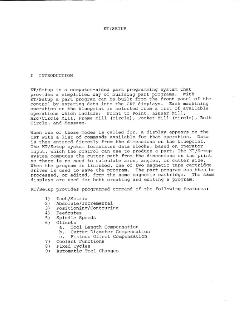
KT/Setup Programming System Information Manual
Computer-aided part programming system documentation covering program building procedures, operation modes (Point to Point, Linear Mill, Arc/Circle Mill, Frame Mill, Pocket Mill, Bolt Circle, Message), CRT display operations, magnetic tape cartridge storage, and programmed command features including inch/metric modes, absolute/incremental positioning, feedrates, spindle speeds, tool length compensation, cutter diameter compensation, fixture offset compensation, coolant functions, fixed cycles, and automatic tool changes. Includes instructions for editing existing programs and creating new programs in inch or metric modes.
Level 1 Cellular Systems Operating Manual
Operating manual for Level 1 Cellular Systems by Kearney & Trecker Corporation. Publication PUB 945. Includes safety guidelines and operational procedures for metal cutting machine tool systems. Document emphasizes safety as everybody's business with comprehensive safety precautions and operational guidance.
Lubrication Manual – K&T Milling Machines
Lubrication manual for Kearney & Trecker plain, universal and vertical knee type milling machines, covering models 210CH-14, 310CH-14, 315CH-16, 415CH-16, S-12 series, TF series, and Milwaukee-Mil bed type production milling machines. Contains lubrication data, oil level maintenance procedures, oil change intervals, and general lubrication practices for regular machine maintenance.
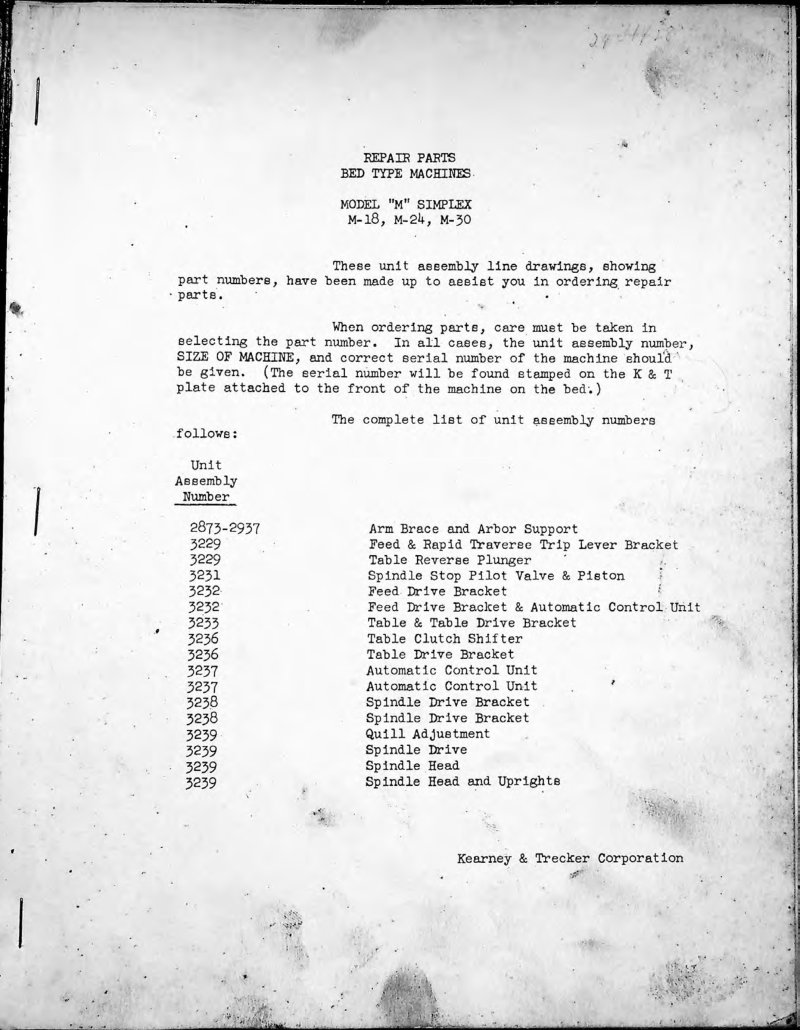
M-18; M-24; M-30 Simplex Parts List
Repair parts book for Milwaukee Simplex bed type milling machines models M-18, M-24, and M-30. Includes unit assembly line drawings with part numbers, complete list of unit assembly numbers with descriptions, plan dimensions (overall height, table dimensions, specifications), general specifications covering table working surfaces, feed ranges, double overarms, arbor supports, spindle details, speeds, feeds, rapid traverse, drive system, and shipping data. Features schematic diagram showing machine layout and component positions. Catalog No. BR11 by Kearney & Trecker Corporation.
M-Series Simplex Milling Machines Operation Manual
Operation, lubrication and adjustment instruction manual for Milwaukee M-Series Simplex milling machines (models M-18, M-24, M-30) manufactured by Kearney & Trecker Corporation. Covers uncrating, hoisting and handling procedures, shortages checking, and includes comprehensive cutting speed selection charts with RPM and cutter diameter guidelines for various materials including aluminum, brass, bronze, cast iron, malleable iron, and steel. Machine weight approximately 5,000 pounds.
Mil-Waukee-Mil Owner's Manual
Care and Operation manual for the Mil-Waukee-Mil milling machine by Kearney & Trecker Corporation. Covers uncrating and cleaning procedures, machine placement on various foundations, leveling instructions, belt drive alignment and tension, motor drive setup, and lubrication instructions for the machine's central reservoir system. Includes guidance on proper handling during installation and initial maintenance before operation.
Milling and Slotting Head Parts List
Replacement parts manual for Kearney & Trecker milling and slotting head attachments and accessories. Publication PUB 258A-751 (ATR-69A), August 1977. Includes visual index, exploded views with numbered parts, and parts identification instructions. Contains sections on how to identify and order replacement parts with item numbers and descriptions.
Milling Heads Parking Attachments Parts Manual
Replacement parts manual No. AR-30 for Kearney & Trecker Milwaukee milling machines. Covers milling heads, parking brackets and attachment cranes, and rapid parking attachments. Published 1956. Includes foreword on parts replacement procedures and visual indexing of assemblies on pages 6-9.
Milling Heads Parking Brackets Rapid Parking Parts List
Replacement parts manual for Kearney & Trecker milling machines. Covers milling heads, parking brackets, attachment cranes, and rapid parking attachments. Published 1956, catalog AR-30, price $3.00.
Milwaukee 2K & 3K Vertical Mill Repair Parts
Repair parts book for Milwaukee Models 2K and 3K vertical milling machines. Contains unit assembly line drawings with part numbers for ordering repair parts. Includes complete list of unit assembly numbers with component identification (vertical column, pulley bracket, feed gear train, elevating screw assembly, knee, table, saddle, vertical head, coolant pump, speed gear box, control brackets, and feed distribution boxes). Document is Bulletin No. 617A from Kearney & Trecker Corporation.
Milwaukee 2K and 3K Milling Machines Operation Manual
Operation manual for Milwaukee Milling Machines Models 2K and 3K (Plain, Universal, and Vertical). Covers uncrating, shortages, hoisting, cleaning, placing on solid foundation, motor or belt drive installation, speed and rotation direction, motor setting, belt placement and adjustment, column lubrication, and machine leveling procedures. Instructions for proper setup and initial operation.
Milwaukee Assembly Practice Manual
Assembly Practice manual from Kearney & Tracker Corporation for Milwaukee Machine Tools. Document Pub. 284 contains guidelines and best practices for assembly work, emphasizing quality control and the pride in craftsmanship. The manual stresses that quality is what the company sells and what customers buy, highlighting the importance of machinists producing quality parts to specification and assemblers using recommended quality methods and practices. Table of Contents: - Chapter 1 Housekeeping and Safety - Chapter 2 Parts Handling - Chapter 3 Unit Assembly – General - Chapter 4 Unit Assembly – Preparatory - Chapter 5 Unit Assembly – Taper Roller Bearings - Chapter 6 Unit Assembly – Ball Bearings - Chapter 7 Unit Assembly – Thrust Bearings - Chapter 8 Unit Assembly – Needle Bearings - Chapter 9 Unit Assembly – Straight Roller Bearings - Chapter 10 Unit Assembly – Spur Gears - Chapter 11 Unit Assembly – Bevel Gears - Chapter 12 Unit Assembly – Worm Drives - Chapter 13 Unit Assembly – Spiroid Gear Drives - Chapter 14 Unit Assembly – Spindles and Transmission Shafts - Chapter 15 Unit Assembly – Dowels and Pins - Chapter 16 Unit Assembly – Springs and Expansion Plugs - Chapter 17 Unit Assembly – Snap Rings - Chapter 18 Unit Assembly – Oil Seals - Chapter 19 Unit Assembly – O-Rings - Chapter 20 Unit Assembly – Couplings - Chapter 21 Unit Assembly – Hardened Ways - Chapter 22 Unit Assembly – Screw Torquing - Chapter 23 Unit Assembly – Recirculating Bearings - Chapter 24 Unit Assembly – Fixtures - Chapter 25 Hydraulic - Chapter 26 Servo Hydraulics - Chapter 27 Lubrication - Chapter 28 Scraping - Chapter 29 Leveling - Chapter 30 Erection - Chapter 31 Geometry Checking - Chapter 32 Electrical Precautions
Milwaukee Electrical Assembly Practice Manual
Electrical assembly practice manual from Kearney & Trecker Corporation for Milwaukee machine tools. Published in 1971. Publication number 292. Document covers electrical assembly procedures and practices. Table of Contents: - Chapter I. Technical Terms, Symbols, Abbreviations, Sample Diagrams, etc. - 1.1 Device Designations and Examples - 1.2 Graphic Symbols for Electric Diagrams with Basic Device Designations - 1.3 Sample Electric Diagrams - 1.4 Glossary of Basic Electrical Terms - 1.5 Glossary of Numerical Control Terms - 1.6 Oscilloscope, Symbols and Abbreviations - 1.7 Oscilloscope, Glossary of Terms - 1.8 Glossary of Commonly Used Computer Terms - Chapter II. Safety Codes - 2.1 Safety in Machine Wiring - 2.2 Safety in Electrical Maintenance - 2.3 First Aid and Resuscitation - Chapter III. Soldering Principles and Techniques - Chapter IV. Solderless Wrapped Connections - Chapter V. Wire Building - Chapter VI. Wire Connections - 6.1 Application of Wire Terminals - 6.2 Common Terminal-Tongue Styles - 6.5 Wire Combination Range - 6.6 Trimi-Point Type - Chapter VII. Cable Plugs - 7.1 Part Number Explanation - 7.2 Contact Arrangements - 7.3 Preparation and Assembly Instructions - 7.4 Testing - Chapter VIII. Terminal Blocks - Chapter IX. Rigid Conduit - 9.1 Glossary of Terms - 9.2 Bending Instructions - 9.3 Formulas and Tables for Bending - 9.17 Hand Bending E.M.T. - Chapter X. Fittings - Chapter XI. Flexible Conduit - 11.1 Flexible, Liquid-Tight Conduit - 11.7 Non-Metallic Flexible Conduit - Chapter XII. Multi Conductor Cables
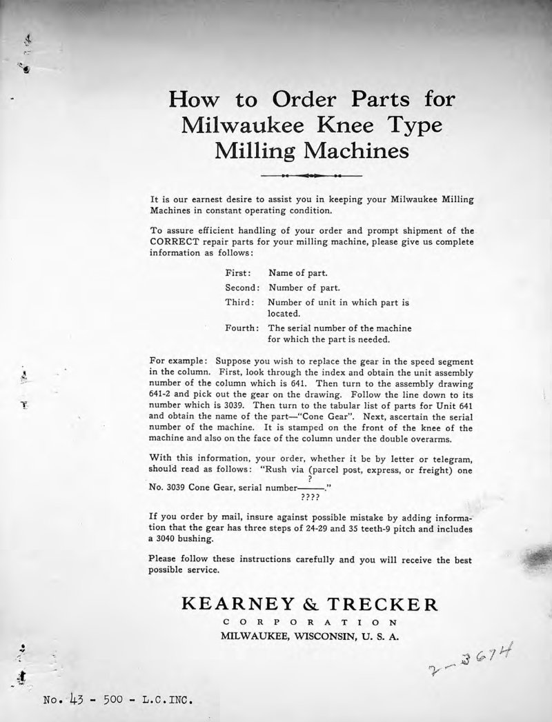
Milwaukee Knee Type Milling Machines Parts List
Repair parts book for Milwaukee knee type milling machines models No. 1, 2, and 3 (standard and heavy duty). Contains unit assembly numbers (630-2146), part identification drawings, tabular parts lists with included stock components, and ordering instructions. Catalog No. 43 published by Kearney & Trecker Corporation, Milwaukee, Wisconsin.
Milwaukee Mill 1400-1800 Operator's Manual
Operator's manual No. MMC-60 for Kearney & Trecker Milwaukee Mill bed type milling machine, models 1400-1800. Covers machine description, feed change, handcranking, backlash and gib adjustments, spindle head operation including speed change, spindle direction control, head positioning, head power feed, quill positioning, automatic quill retraction, hydraulic quill clamping, spindle bearing adjustment. Includes sections on overarms and arbors (positioning, supports, installation, bearing adjustment, brace, arbor installation), measuring system, coolant system, lubrication and hydraulics, electrical system (cabinet, Dial-A-Cycle panel, control pendant, trip post), trip dogs, set-up procedures (manual cycle, automatic cycle, plain cycle, intermittent cycle, reciprocycle, reciprocycle with automatic quill retraction, plain vertical head cycle, box cycle), operation, preventive maintenance, and basic machine dimensions. Table of Contents: - Machine Description - Table - Feed Change - Handcranking The Table - Backlash Adjustment - Gib Adjustment - Spindle Head - Speed Change - Spindle Direction Control - Head Positioning - Head Power Feed - Quill Positioning - Automatic Quill Retraction - Hydraulic Quill Clamping - Spindle Bearing Adjustment - Gib Adjustment - Overarms and Arbors - Overarm Positioning - Arbor Supports - Arbor Support Installation - Arbor Support Bearing Adjustment - Overarm Brace - Arbor Installation - Measuring System - Coolant System - Lubrication and Hydraulics - Electrical System - Cabinet - Dial-A-Cycle Panel - Control Pendant - Trip Post - Trip Dogs - Set-Up - Manual Cycle - Automatic Cycle - Plain Cycle - Intermittent Cycle - Reciprocycle - Reciprocycle With Automatic Quill Retraction - Plain Vertical Head Cycle - Box Cycle - Operation - Preventive Maintenance - Basic Machine Dimensions
Milwaukee Milling Machines Lubrication Manual
Lubrication manual for Milwaukee milling machines manufactured by Kearney & Trecker Corporation. Covers lubrication procedures for horizontal knee type machines (Manufacturing, Plain, Universal models), vertical knee type machines (Manufacturing, Plain models), bed type machines (Simplex, Duplex, Bridge Type Vertical), face mill grinders, rotary head tool and die machines, overarms, motors, arbor supports, and Milwaukee milling attachments. Includes lubrication specifications and maintenance guidelines for high-production machine tools.
Milwaukee Milling Machines Models 2K & 3K Instruction Book
Instruction book for Kearney & Trecker Milwaukee milling machines models 2K and 3K, covering plain, universal, and vertical configurations. This workshop manual provides detailed guidance on machine operation, setup, and long-term maintenance. Contents include uncrating and initial inspection procedures, hoisting and foundation placement, machine leveling and alignment, motor and belt drive installation with speed and rotation direction settings, sheave configuration, and comprehensive lubrication schedules with specific maintenance intervals for the column and drive system. Also addresses cleaning protocols, shortage reporting, and troubleshooting adjustments to keep the machine running reliably. An essential service manual and reference guide for anyone operating or maintaining these industrial milling machines.
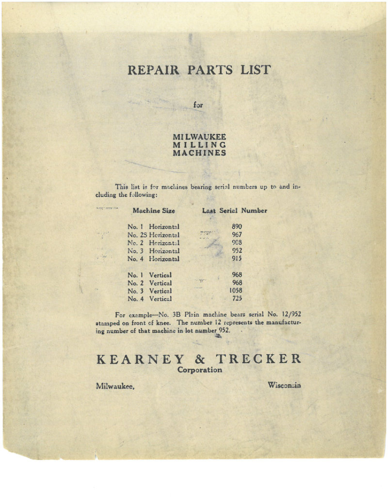
Milwaukee Milling Machines Parts List
Repair parts list for Milwaukee milling machines covering horizontal and vertical models No. 1 through No. 4. Includes serial number ranges, parts identification with numbered components, and detailed part names for both horizontal machines (serial numbers up to 967) and vertical machines (serial numbers up to 1058). Document provides ordering guidance for repair and replacement parts.
Milwaukee S-12 and S-15 Maintenance Manual
Maintenance Manual No. SM-66 for Kearney & Trecker Milwaukee S-12 and S-15 plain, universal, and vertical milling machines. First Edition May 1966. Includes labeled diagram of plain style milling machine left front view with component identification such as overarm, control pendant, table clamp lever, mono-lever, feed selector dial, power feed lever, rear control handcrank, and automatic backlash control knob.
Milwaukee VB-2 Programming and Operating Manual
Part programming and operating manual supplement for the Milwaukee VB-2 machine tool with KT-Gemini-E machine control system. Contains safety guidelines and operational procedures for metal cutting machine tool operations. Publication PUB 819A, with safety documentation PUB-578 included. First edition, May 1976. Table of Contents: - The employer is responsible for selecting competent and qualified employees - Manuals are provided with each machine tool, the user should have these available for personnel working with the machine tool - Guards and shields are to be in place at all times - Operators must be forbidden from changing workpieces or performing other work close to a revolving cutter - When contaminants are released to the atmosphere as a result of machining, an exhaust system is recommended - All employees should be aware of first aid facilities and be encouraged to use same - Employees should be encouraged to report to their supervisors any hazardous condition on the machine tool or in the immediate area - Air hoses - it is recommended that air hoses not be available for use around the machine tool - Levels of illumination in the immediate area of the machine tool should comply with National Standards - Fire prevention must be practiced and fire protection available to prevent loss of life, personal injury and to protect property - Protective footwear - safety shoes afford good protection against rolling objects, dropping heavy objects, accidentally kicking sharp edged materials - Eye protection - eye protection devices must be considered as optical instruments and should be carefully selected, fitted and used - The employer must insist that his employees study this safety information and practice safety - Users must have available adequate lifting facilities capable of lifting within the safe load limits; also appropriate slings and hitches - Every floor opening resulting from the machine tool installed in pits or below floor level should be covered with a material of proper strength with non-slip features - When machines are installed above floor level and a platform is built around the machine tool, the platform must be constructed of materials of proper strength with non-slip features of the walking surfaces - Management personnel have the responsibility to alert operating personnel of any unsafe practice they may observe
Milwaukee VB-2, VB-4, HB-4 Replacement Parts Manual
Replacement parts manual for Milwaukee Series VB-2, VB-4, and HB-4 machining and milling centers equipped with KT-Gemini-E control. Includes safety guidelines and parts information. Table of Contents: - Vertical Head Assembly (Figure CA through CJ, Pages 10-27) - Power Draw Rod (Figure EA, Pages 40-41) - Enclosure VB-2 (Figure KA, Pages 106-107, Not Illustrated) - Chip Conveyor (Figure 5A, Pages 154-155) - Table and Wear Plates VB-2 (Figure AA, Pages 6-7) - Rotary Table 4th Axis (Figure QA through QC, Pages 144-149, Not Illustrated) - Indexer (Figure RA through RB, Pages 150-153, Not Illustrated) - Vertical Upright (Figure MA through MF, Pages 110-121) - Side Access Door VB-2 (Figure HH, Pages 76-77) - Pendant Support (Figure UA, Pages 158-159) - KT Gemini "E" Control (Figure YA through YK, Pages 166-185) - 18 Tool Storage VB-2 (Figure FA through FE, Pages 42-51) - Bed Assembly VB-2 (Figure HA through HG, Pages 62-75)
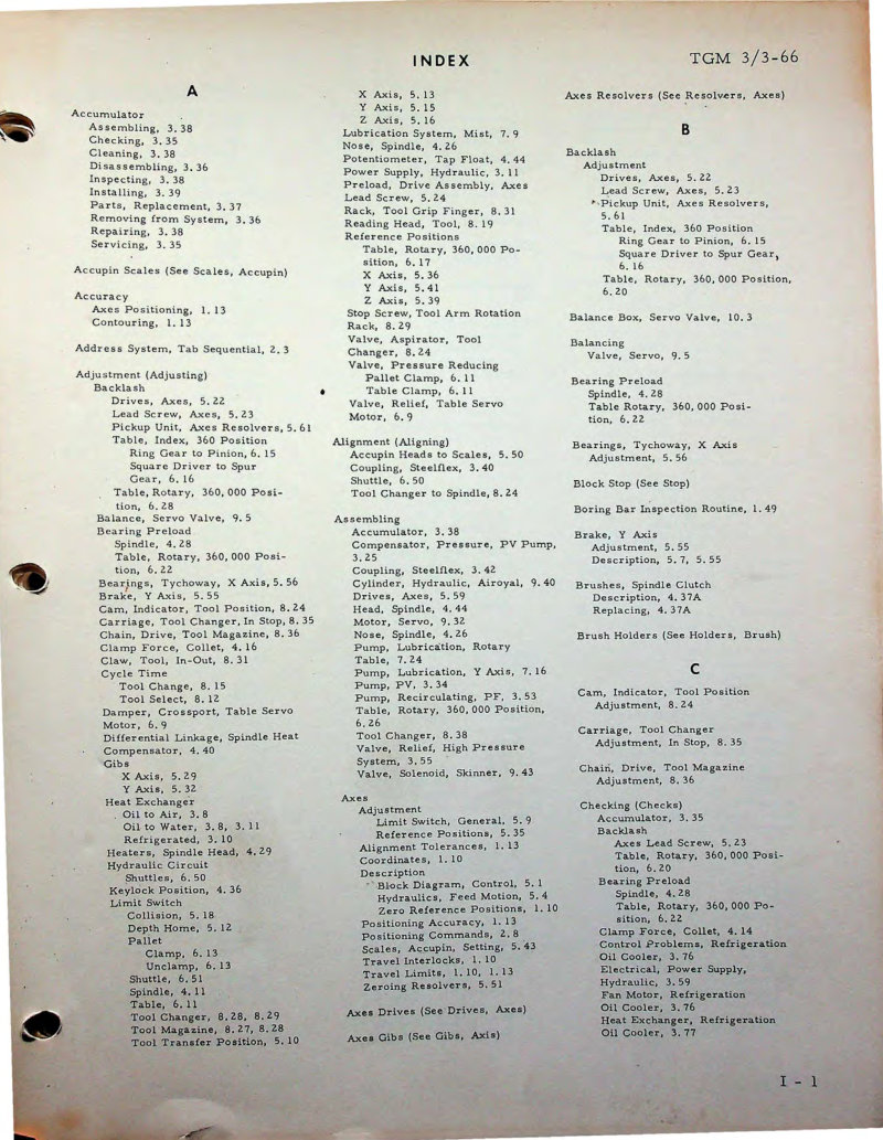
Milwaukee-Matic 3-axis Model III Maintenance Manual
Maintenance manual TGM 3/3-66 for the Kearney and Trecker Milwaukee-Matic 3-axis Model III mill with solid state numerical control. Contains comprehensive index covering maintenance, adjustments, lubrication, tool changers, hydraulic systems, coolant systems, spindle operations, and servo motors. 119 pages total. Table of Contents: - Accumulator Assembling - Accumulator Checking - Accumulator Cleaning - Accumulator Disassembling - Accumulator Inspecting - Accumulator Installing - Accumulator Parts, Replacement - Accumulator Removing from System - Accumulator Repairing - Accumulator Servicing - Accupín Scales (See Scales, Accupín) - Accuracy Axes Positioning - Accuracy Contouring - Address System, Tab Sequential - Adjustment Backlash - Adjustment Backlash Drives, Axes - Adjustment Backlash Lead Screw, Axes - Adjustment Backlash Pickup Unit, Axes Resolvers - Adjustment Backlash Table, Index, 360 Position - Adjustment Backlash Ring Gear to Pinion - Adjustment Backlash Square Driver to Spur Gear - Adjustment Backlash Table, Rotary, 360,000 Position - Adjustment Balance, Servo Valve - Adjustment Bearing Preload - Adjustment Bearing Preload Spindle - Adjustment Bearing Preload Table, Rotary, 360,000 Position - Adjustment Brake, Y Axis - Adjustment Cam, Indicator, Tool Position - Adjustment Carriage, Tool Changer, In Step - Adjustment Chain, Drive, Tool Magazine - Adjustment Clamp Force, Collet - Adjustment Claw, Tool, In-Out - Adjustment Cycle Time - Adjustment Damper, Crossfeed, Table Servo - Adjustment Motor - Adjustment Differential Linkage, Spindle Heat - Adjustment Compensator - Adjustment Gibs, X Axis - Adjustment Gibs, Y Axis - Adjustment Heat Exchanger - Adjustment Oil to Air - Adjustment Oil to Water - Adjustment Refrigerated - Adjustment Spindle Head - Adjustment Hydraulic Circuit - Adjustment Shuttle - Adjustment Keylock Positioning - Adjustment Limit Switch - Adjustment Collision - Adjustment Depth Home - Adjustment Pallet Clamp - Adjustment Pallet Unclamp - Adjustment Shuttle - Adjustment Spindle - Adjustment Table - Adjustment Tool Changer - Adjustment Tool Magazine - Adjustment Tool Transfer Position - X Axis - X Axis - Y Axis - Z Axis - Lubrication System, Mist - Nose, Spindle - Potentiometer, Tap Float - Power Supply, Hydraulic - Preload, Drive Assembly, Axes - Lead Screw - Rack, Tool Grip Finger - Reading Head, Tool - Reference Positions - Reference Positions Table, Rotary, 360,000 Position - Reference Positions X Axis - Reference Positions Y Axis - Reference Positions Z Axis - Stop Screw, Tool Arm Rotation - Stop Screw, Tool Arm Rotation Rack - Valve, Aspirator, Tool Changer - Valve, Pressure Reducing - Valve, Pressure Reducing Pallet Clamp - Valve, Pressure Reducing Table Clamp - Valve, Relief, Table Servo - Motor - Alignment Accupín Heads to Scales - Alignment Coupling, Steelflexes - Alignment Shuttle - Alignment Tool Changer to Spindle - Assembling Accumulator - Assembling Compensator, Pressure, PV Pump - Assembling Coupling, Steelflexes - Assembling Cylinder, Hydraulic, Airoyal - Assembling Drives, Axes - Assembling Head, Spindle - Assembling Motor, Servo - Assembling Nose, Spindle - Assembling Pump, Lubrication, Rotary - Assembling Table - Assembling Pump, Lubrication, Y Axis - Assembling Pump, PV - Assembling Pump, Recirculating, P.F. - Assembling Table, Rotary, 360,000 Position - Assembling Tool Changer - Axes Resolvers (See Resolvers, Axes) - Backlash Adjustment - Backlash Adjustment Driver, Axes - Backlash Adjustment Lead Screw, Axes - Backlash Adjustment Pickup Unit, Axes Resolvers - Backlash Adjustment Table, Index, 360 Position - Backlash Adjustment Ring Gear to Pinion - Backlash Adjustment Square Driver to Spur Gear - Backlash Adjustment Table, Rotary, 360,000 Position - Balance Box, Servo Valve - Balancing Valve, Servo - Bearing Preload Spindle - Bearing Preload Table, Rotary, 360,000 Position - Bearings, Tychoway, X Axis - Bearings, Tychoway, X Axis Adjustments - Block Stop (See Stop) - Boring Bar Inspection Routine - Brake, Y Axis - Brake, Y Axis Adjustment - Brake, Y Axis Description - Brushes, Spindle Clutch Description - Brushes, Spindle Clutch Replacing - Brush Holders (See Holders, Brush) - Cam, Indicator, Tool Position - Cam, Indicator, Tool Position Adjustment - Carriage, Tool Changer - Carriage, Tool Changer Adjustment, In Step - Chain, Drive, Tool Magazine - Chain, Drive, Tool Magazine Adjustment - Checking (Checks) - Checking (Checks) Accumulator - Checking (Checks) Backlash - Checking (Checks) Backlash Axes Lead Screw - Checking (Checks) Backlash Table, Rotary, 360,000 Position - Checking (Checks) Bearing Preload - Checking (Checks) Bearing Preload Spindle - Checking (Checks) Bearing Preload Table, Rotary, 360,000 Position - Checking (Checks) Clamp Force, Collet - Checking (Checks) Control Problems, Refrigeration - Checking (Checks) Oil Cooler - Checking (Checks) Electrical, Power Supply - Checking (Checks) Hydraulic System - Checking (Checks) Fan Motor, Refrigeration - Checking (Checks) Leak Test - Checking (Checks) Heat Exchanger, Refrigeration - Checking (Checks) Oil Cooler
Milwaukee-Matic Co-Ordinator Planning Guide
Planning guide for Milwaukee-Matic manufacturing system coordinators. Covers system organization, personnel roles, facilities requirements, process planning, production setup, quality control, and maintenance. Includes sections on the Milwaukee-Matic method as a flexible multiple operation machining center and guidance for establishing an effective coordination structure. Published by Kearney & Trecker Corporation, PUB 305, August 1978.
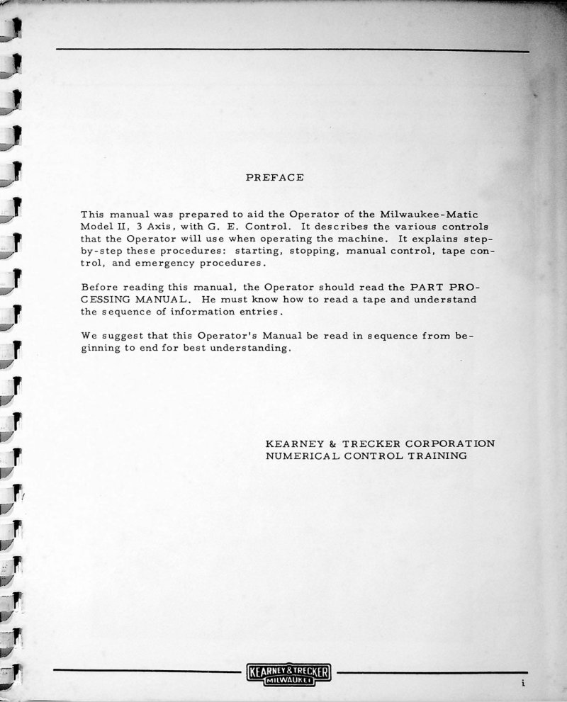
Milwaukee-Matic Model II Operator's Manual
Operator's manual for the Kearney & Trecker Milwaukee-Matic Model II, 3 Axis with G.E. Control (Model No. TGC2-62PC). Describes controls and step-by-step operating procedures including starting, stopping, manual control, tape control, and emergency procedures. Prepared by Kearney & Trecker Corporation Numerical Control Training.
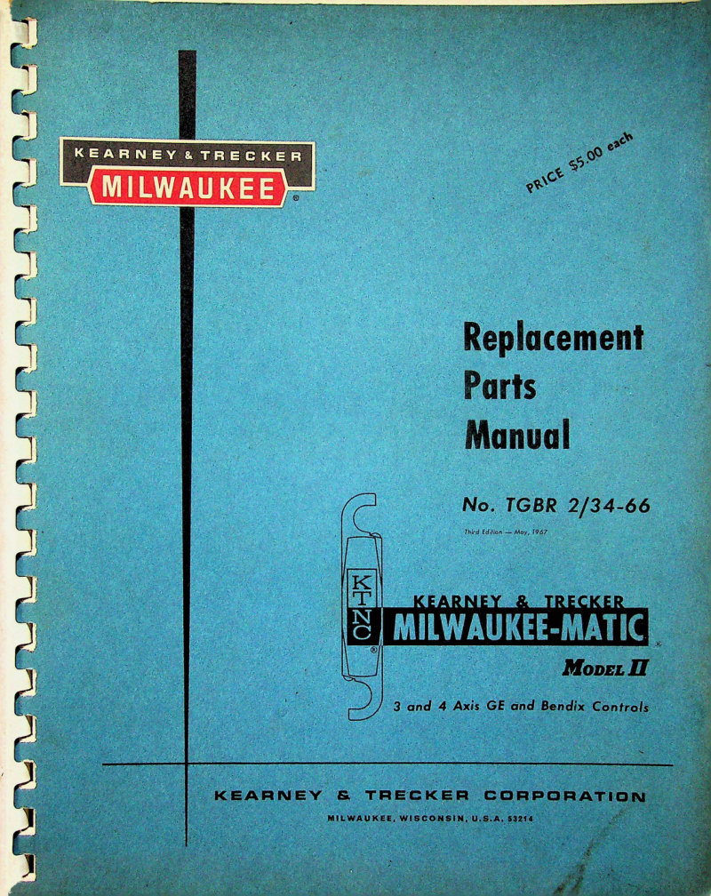
Milwaukee-Matic Model II Parts List
Replacement parts manual for Kearney & Trecker Milwaukee-Matic Model II milling machine with 3 and 4 axis GE and Bendix controls. Manual No. TGBR 2/34-66, Third Edition May 1967. 82 pages.
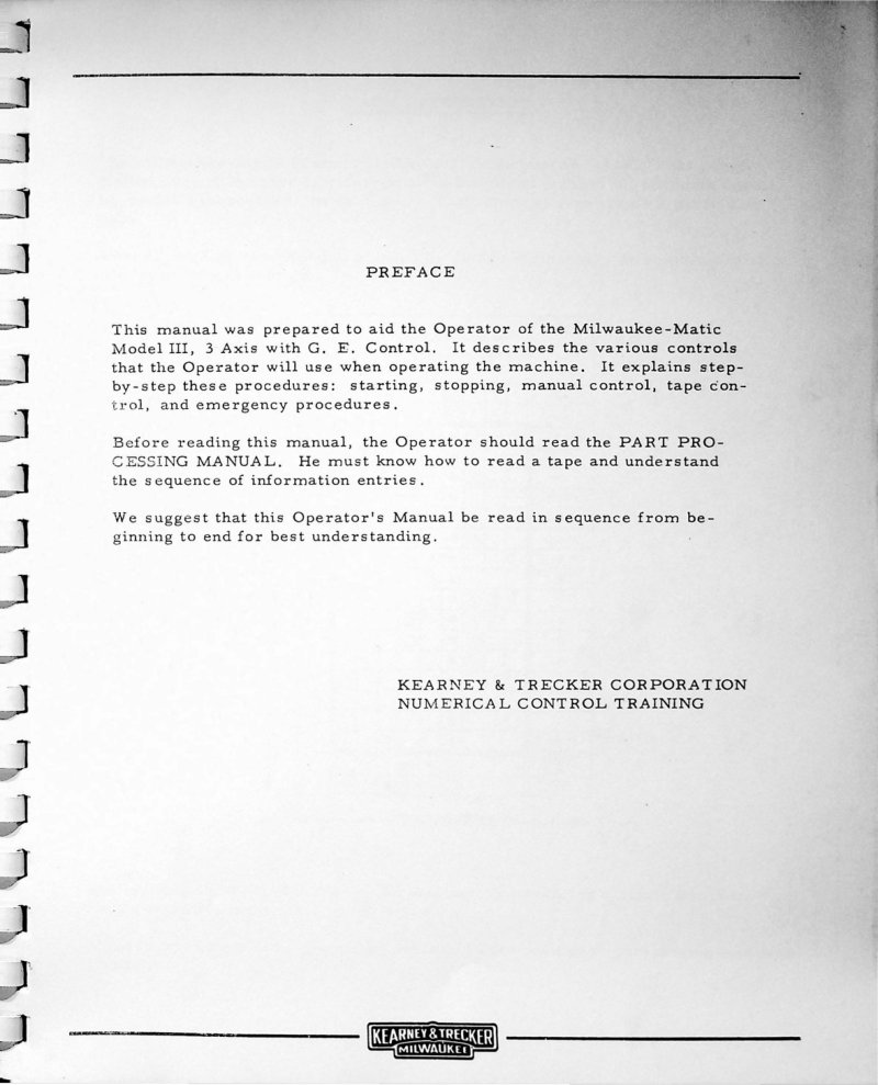
Milwaukee-Matic Model III Operator's Manual
Operator's manual for the Kearney & Trecker Milwaukee-Matic Model III 3-axis machine with G.E. Control (NPC-HCC Control). Covers controls, operating procedures including starting, stopping, manual control, tape control, and emergency procedures. Operators must first read the Part Processing Manual to understand tape reading and information sequence.
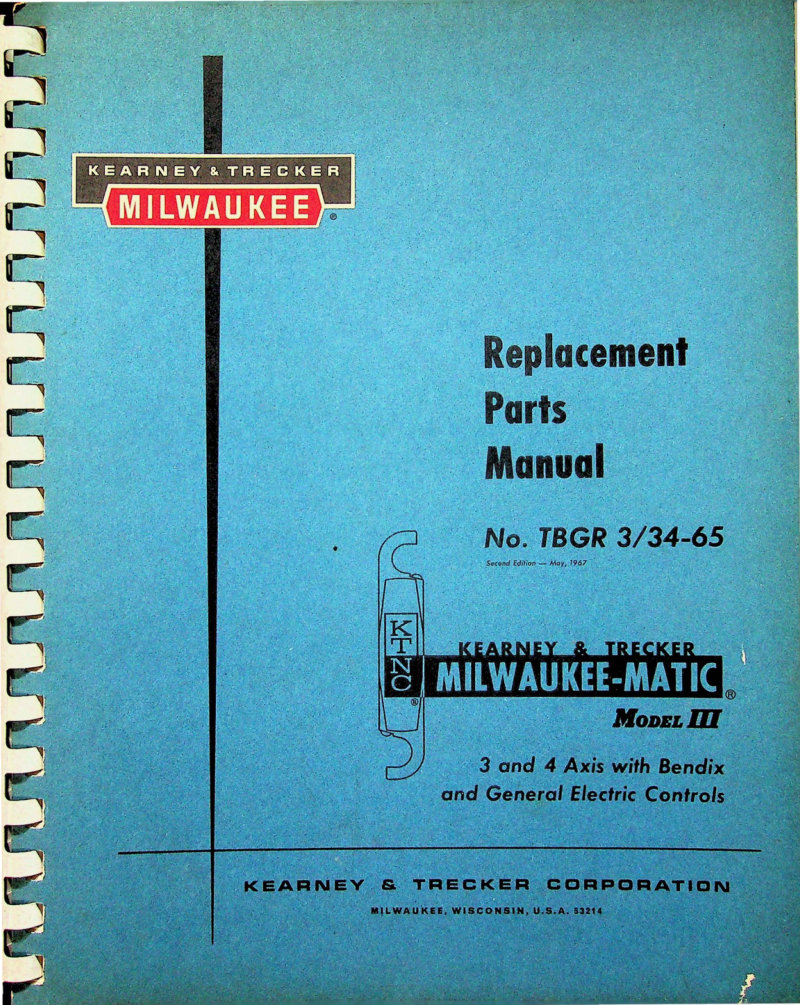
Milwaukee-Matic Model III Parts Manual
Replacement parts manual for Kearney & Trecker Milwaukee-Matic Model III CNC machines (TBGR 3/34-65). Second Edition from May 1967. Covers 3 and 4 axis configurations with Bendix and General Electric controls. Contains service update record section for tracking revisions and updates to the manual.
Milwaukee-Matic Part Processing Manual
Part Processing Manual No. TGP235/3-66 (Third Edition, October 1966) for Kearney & Trecker Milwaukee-Matic Models II, III, and V 3-axis machines with General Electric controls. Covers NPC and NPC-NCC systems. Contents include machine description, tape-controlled and operator-controlled functions, coordinate system, spindle specifications, linear axis drives, tool magazine operation, tool specifications, tape format and preparation, program entries, and information storage. Third edition issued January 1966. Table of Contents: - Machine Description - Basic NPC Single System - Tape Controlled Functions - Operator Controlled Functions - Coordinate System - NPC - NCC Dual System (Option) - Spindle - Spindle Keylock (II Option) (III & V Standard) - Linear Axis Drives - Index Table - Pallet - Fixture Locating Gage Blocks (III & V) - Shuttles - Tool Magazine and Changer - Tools - Manual Data Input and Readout Screen (Option) - Portable Control Box (Option) - Computer Assisted Programming - Machine Specifications - Axis Travel Ranges - Axes Coordinate System - Accuracy - Spindle - Spindle Speed and Horsepower - Feed Rate - Tool Changer - Table - Machine Specifications - Introduction - Process Planning Sheet - Tab Sequential Address System - Program Entries Summary - Information Storage - Tape Format and Preparation - Tape Description - Tape Codes - Tape Preparation - Tape Correction - Splicing the Tape - Revising the Tape - Duplicating the Tape
Milwaukee-Matic Series E Part Processing Manual
Part Processing Manual for Milwaukee-Matic Series E machines (model EGP/3-66). Second Edition, January 1967. Published by Kearney & Trecker Corporation, Milwaukee, Wisconsin. Includes service update record table for tracking revision levels and processing documentation. Manual contains instructions and technical information for parts processing operations. Table of Contents: - Machine Description - Introduction - Modes of Operation - Machine - Operator's Console - Machine Control Unit (MCU) - Power Distribution Panel (PDP) - Hydraulic Power Supply (HPS) - Specifications - Axes Coordinate System and Setup Positions - Zero Reference Position - Collision Interlock Zone - Axis Travel Limits - Feed Rates - Spindle - Index Table and Table Base - Automatic Tool Changer and Tool Magazine - Machine Accuracy - Machine Language - Programine - Block Unit Input - Process Planning Sheet - Letter Address System - Program Entries Summary - Control Tape Format and Preparation - Tape Description - Tape Material - Tape Codes - Sample Tape - Tape Preparation - Tape Correction - Splicing the Tape - General Programming - Introduction - Sequence Numbers - Preparatory Commands - Positioning Mode Axis Commands and Feed Rates - Contouring Axis and Feed Rate Commands - General - Slope Contouring Axis Commands and Feed Rate Numbers - Arc Contouring Axis Commands and Feed Rate Numbers - Table Index Commands - Spindle Speed Commands
Milwaukee-Matic Series E Part Processing Manual
Part Processing Manual No. MEP-64 for Milwaukee-Matic Series EA 3-axis machine tool with Square D Rapac Static Logic Control. First Edition, February 1964. Published by Kearney & Trecker Corporation. Document includes programmer manual covering CNC machine tool operation and part programming procedures. Table of Contents: - General - Specifications - Capabilities - Programming Language - Programming Language on Tape - Programming Rules - Preparation for Programming - Example Program

Milwaukee-Matic Series Eb Installation Manual
Installation manual for the Kearney & Trecker Milwaukee-Matic Series Eb machine tool. Contains complete instructions for installing the machine, including foundation preparation, uncrating, cleaning, setting on holddown studs, positioning hydraulic and electrical cabinets, power distribution connections, hydraulic reservoir filling, and rough leveling. Includes guidance on work that can be expedited by the customer before the Kearney & Trecker serviceman arrival.
Milwaukee-Matic Series Eb Maintenance Manual
Maintenance manual for the Milwaukee-Matic Series Eb 3 axis machine with General Electric Controls. Document No. EGM/3-66, fourth edition from September 1967. Published by Kearney & Trecker Corporation, Milwaukee, Wisconsin. Table of Contents: - Machine Description - Introduction - Modes of Operation - Machine - Operator's Console - Machine Control Unit (MCU) - Power Distribution Panel - Hydraulic Power Supply (HPS) - Specification - Machine Controls and Indicators - Starting the Machine - Synchronizing the Control and the Axes - Using Axis Offset - Stopping the Machine - Machine Operation Using Manual Data Input Positioning Mode - Generating a Slope Using Manual Data Input (Optional Positioning/Contouring System Only) - Generating an Arc Using Manual Data Input (Optional Positioning/Contouring System Only) - Machine Operation in AUTO Mode - Operator Control in AUTO Mode - Manual Entries While in AUTO Mode - Tool Loading Considerations - Loading and Operating the Rheem Tape Reader - Hand Cranked Movement of the Axes - Machine Language - Program - Block Unit Input - Process Planning Sheet - Letter Address System - Program Entries Summary - Tape Description - Tape Material - Functional Tape Codes
Milwaukee-Matic Series Eb Operator's Manual
Operator's manual for Milwaukee-Matic Series Eb with General Electric Control. First issue, April 1966. Published by Kearney & Trecker Corporation, Milwaukee, Wisconsin. 52 pages covering operation and use of the machine tool control system. Table of Contents: - Machine Description - Introduction - Modes of Operation - Machine - Operator's Console - Machine Control Unit (MCU) - Power Distribution Panel (PDP) - Hydraulic Power Supply (HPS) - Machine Options - Specifications - Axes Coordinate System and Setup Positions - Zero Reference Position - Collision Interlock Zone - Axis Travel Limits - Feed Rates - Spindle - Index Table and Table Base - Automatic Tool Changer and Tool Magazine - Machine Accuracy - Machine Language - Program - Block Unit Input - Process Planning Sheet - Letter Address System - Program Entries Summary - Control Tape Format and Preparation - Tape Description - Tape Material - Tape Codes - Sample Tape - Tape Preparation - Tape Correction - Splicing the Tape - Machine Controls and Indicators - Power Distribution Panel ON-OFF Circuit Breaker - Master Start Button - Mode Selector Switch - Standard Grid Setup Button - Cycle Start Button Indicator - Manual Data Input Switches and Buttons
Milwaukee-Matic Series Eb Operator's Manual
Operator's manual for the Milwaukee-Matic Series Eb machine (model EGC/3-66). Published by Kearney & Trecker Corporation, Milwaukee, Wisconsin. Document number EGC/3-66. Includes service update record information explaining the identification numbering system for service updates and revision tracking procedures. Table of Contents: - Machine Description - Introduction - Modes of Operation - Machine - Operator's Console - Machine Control Unit (MCU) - Power Distribution Panel (PDP) - Hydraulic Power Supply (HPS) - Specifications - Axes Coordinate System and Setup Positions - Zero Reference Position - Collision Interlock Zone - Axis Travel Limits - Feed Rates - Spindle - Index Table and Table Base - Automatic Tool Changer and Tool Magazine - Machine Accuracy - Machine Language - Program - Block Unit Input - Process Planning Sheet - Letter Address System - Program Entries Summary - Control Tape Format and Preparation - Tape Description - Tape Material - Tape Codes - Sample Tape - Tape Preparation - Tape Correction - Splicing the Tape - Machine Controls and Indicators - Power Distribution Panel ON-OFF Circuit Breaker - Master Start Button - Mode Selector Switch - Standard Grid Setup Button - Cycle Start Button Indicator - Manual Data Input Switches and Buttons
Milwaukee-Matic Series Eb Replacement Parts Manual
Replacement parts manual for the Milwaukee-Matic Series Eb machine tool. Document No. EGR/3-66, First Edition January 1967. Contains detailed exploded views and parts lists for major assemblies including upright, drum-changer housing, spindle head, saddle, bed, Y-axis drive, X-Z axis drive, and hydraulic power supply. Indexed component diagrams with figure references and page numbers for each major system. Table of Contents: - Upright (Fig. A thru G, Pages 4-17) - Drum-Changer Housing (Fig. H thru N, Pages 18-29) - Spindle Head (Fig. P thru W, Pages 30-45) - Y Axis Drive (Fig. X thru AA, Pages 46-53) - Bed (Fig. BB thru EE, Pages 54-61) - X-Z Axis Drive (Fig. FF thru HH, Pages 62-67) - Saddle (Fig. JJ thru NN, Pages 68-77) - Index Table (Fig. PP thru RR, Pages 78-83) - Hydraulic Power Supply (Fig. SS thru UU, Pages 84-89)
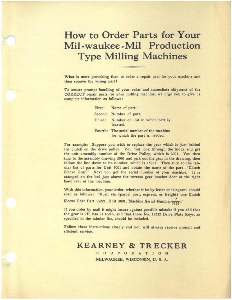
Milwaukee-Mil Production Milling Machines Parts List
Parts list for Milwaukee-Mil Production Type Milling Machines. Contains instructions for ordering repair parts with guidance on providing correct part names, numbers, unit assembly locations, and machine serial numbers. Includes comprehensive tabular list of unit assembly numbers (3001-3089) with corresponding part names covering drive pulley brackets, speed gear boxes, chip pans, arbor supports, oil piping, feed control systems, coolant piping, safety clutches, table models, machine heads, and cam feed machines. Document dated August 30, 1929. Table of Contents: - Drive pulley bracket & Lubricating Pump - Spindle Reverse Gear Bracket - Pick-Off Speed Gear Box (Simplex) - Quick Change Speed Gear Box (Simplex) - Chip Pans (1405-1407-1408-1411) - Chip Pans (2205-2207-2208-2211) - Arbor Support and Arm Braces (Simplex) - Arbor Support and Arm Braces (Duplex) - Oil Piping (Simplex) - Oil Piping (Duplex) - Automatic Feed Control - Feed Pinion Bracket - Chip Pans (1402) - Chip Pans (1403-1404) - Pick-Off Speed Gear Box (Duplex) - Quick Change Speed Gear Box (Duplex) - Belt Drive Parts - Motor Drive Parts - Coolant Piping (Simplex) - Coolant Piping (Duplex) - Coolant Piping (Triplex) (For One Head) - Coolant Piping (Triplex) (For Two Heads) - Pick-Off Feed Box - Chip Pans (2202-2203-2204) - Quick Change Feed Box - Safety Clutch (1400 Series) - Safety Clutch (2200 Series)
MM 200/600 HMC with KT-Gemini D-17 Manual
Programming and operating manual for the MM 200/600 machining center equipped with KT-Gemini D-17 control system. Includes safety guidelines and operational procedures. Published by Kearney & Trecker Corporation, Milwaukee, Wisconsin. 327 pages total. Table of Contents: - Machine and Control Description - Basic Machine Description - Machine Control Unit - Standard Control Features - Modes of Operation - Optional Control Features - Power Distribution Panel - Hydraulic Power Supply - Machine Specifications - Axes - Axis Travel Limits - Zero Reference Position - Standard Grid - Collision Zone - Pallet - Description - 360 Position Index Table - Rotary Table (Optional) - Table Geometry - Manually Loading a Pallet onto Table Unit - Manually Removing a Pallet from Table Unit - Pallet Shuttle Option - Description - Shuttle Control Panel - Automatic Shuttle Operation, Procedures - The Pallet Shuttle Sequence - Manual Shuttle Operation, Procedures - Transferring a Pallet to Load Station - Operating the Shuttle Rotate Pushbutton - Spindle Head Unit - Spindle Gear Range - Spindle Speeds - Spindle Horsepower - Spindle Configuration - Spindle Configuration - Spindle Overload Protection - 5 Axis Option - Machine Features - Tooling - Tool Changer - Tool Storage Magazine - Feedrate - Coolant Systems - Chip Conveyor
MM 800 Machining Center Programming Manual
Part programming and operating manual (PUB 775) for the MM 800 machining center with KT-Gemini D-17 control. Includes safety guidelines (PUB-578, First Edition May 1976) emphasizing safety procedures for machine tool operation, supervision, and maintenance. 373 pages total. Table of Contents: - Machine and Control Description - Basic Machine Description - Machine Control Unit - Standard Control Features - Modes of Operation - Optional Control Features - Power Distribution Panel - Hydraulic Power Supply - Machine Specifications - Axes - Axes Travel Limits - Zero Reference Position - Standard Grid - Pallet - Description - 360 Position Index Table - Rotary Table (Optional) - Pallet Geometry - Manually Loading a Pallet onto Table Unit - Manually Removing a Pallet from Table Unit - Pallet Shuttle Option - Description - Shuttle Control Panel - Automatic Shuttle Operation and Procedures - Tape Mode - MDI (Manual Data Input) - The Pallet Shuttle Sequence - Manual Shuttle Operation and Procedure - General Prerequisites for Manual Shuttle - Transferring a Pallet to the Index Base - Transferring Pallet to Shuttle Load Station - Operating the Shuttle Rotate Pushbutton - Spindle Head Unit - Spindle Gear Range - Spindle Speeds - Spindle Horsepower - Spindle Configuration (STR SHK Tooling) - Spindle Collet - Axial Tool Retention - Spindle Configuration (Taper Collet) - Taper Size - Tool Retention - Spindle Keylock - Spindle Configuration (Straight Collet) - Collet Size - Tool Retention - Spindle Keylock - Spindle Keylock
MM-180 Machining Center Programming Manual
Programming and operating manual (PUB 773A Volume II) for the MM-180 Machining Center equipped with KT-Gemini D-17 Control. Includes safety information and operational guidelines for machine operators, supervisors, and maintenance technicians. Document emphasizes safety as everybody's business with detailed precautions and foresight-based accident prevention procedures. Table of Contents: - Employer responsibility for selecting competent and qualified employees - Manuals provided with each machine tool - Guards and shields in place at all times - Operators forbidden from changing workpieces near revolving cutters - Exhaust system recommended when contaminants released during machining - First aid facilities awareness and use - Reporting hazardous conditions to supervisors - Air hoses not available around machine tools - Illumination levels complying with National Standards - Fire prevention and protection practices - Protective footwear for safety - Eye protection devices - Employer insistence on safety study and practice - Adequate lifting facilities with safe load limits - Floor openings from machine tools covered with non-slip material - Platforms around machines with non-slip features, railings and toe boards - Management responsibility to alert personnel of unsafe practices
MM-180 Machining Center Programming Manual
Programming and Operating Manual (PUB 773A Volume I) for the MM-180 Machining Center equipped with KT-Gemini D-17 Control. Published by Kearney & Trecker Corporation. Includes safety information and operational guidance for CNC machining center users. Table of Contents: - Machine and Control Description - Basic Machine Description - Machine Control Unit - Standard Control Features - Modes of Operation - Optional Control Features - Power Distribution Panel - Hydraulic Power Supply - Machine Specifications - Axes - Axis Travel Limits - Zero Reference Positions - Standard Grid Positions - Index Base - Axes Fedrate Ranges - Collision Zone - Pallet - Pallet Shuttle - Spindle - Spindle Horsepower - Spindle Gear Range - Spindle Speed - Tool Unclamp/Auto Selector Switch - Tapping - Keylock - Machine Features - Tooling - Tool Holders - Tapered Shank - Straight Shank - Tooling Coding - Tapered Tools - Straight Shank - Tool Changer - Automatic Tool Transfer - Manual Tool Transfer - Tool Storage Magazine - Tool Select Sequence Systems - Jogging the Tool Storage Magazine - Loading the Tool Storage Magazine - Loading, Unloading Tool Storage Magazine - Displaying the Tool Table - Entering, Changing, Cancelling T-Number - Clearing the Entire Tool Table - Coolant - Flood Coolant - Mist Coolant - Coolant Through Spindle (Optional) - Chip Conveyor - Chip and Coolant Shield Package (Optional)
MM-200/600/800 Modu-Line Programming Manual
Part programming and operating manual (PUB 747B) supplement for Kearney & Tracker traveling column modu-line machining centers MM 200/600 and MM 800 equipped with KT-Gemini D-17 control. Includes safety guidelines. First edition from May 1976. Table of Contents: - Compensation Radius with Undersize Cutter - Compensation Radius with Oversize Cutter (Compensation Value Equals Radius) - Compensation Radius with Oversize Cutter (Compensation Value Twice Radius) - Compensation Radius with Oversize Cutter (Compensation Value Greater than Twice Radius) - Broken Tool Detector - Sequence of Operations and Tool Description Sheet - Tool Library - Co-ordinate Calculations - Co-ordinate Calculations - Co-ordinate Sheet - Simplified Co-ordinate Sheet - Blind Hole Drill Travel - Through Hole Drill Travel - Drill and Tap Travel Blind Hole - Side Cutting Travel - MM Tool List - RS358 B Tape Code - RS244 B Tape Code - RS244 B Functional Tape Characters - RS244 B Non-Functional Tape Characters - KT-GEMINI D-17 Control System (Front) - KT-GEMINI D-17 Control System (Right Side) - KT-GEMINI D-17 Control System (Back) - KT-GEMINI D-17 Operators Control Panel - Tape Reader-Spool Loading - Tape Reader-Loop Loading - MM 200/600 Machine Control Switches - MM 800 Machine Control Switches - Traveling Column Modu-Line Machine Control Switches - Broken Tool Detector & Spindle Probe Post Location for MM 200 - Broken Tool Detector & Spindle Probe Post Location for MM 600 - Broken Tool Detector & Spindle Probe Post Location for MM 800 - Broken Tool Detector & Spindle Probe Post Location for MM 800 Extended Travel - Adaptive Control Parameters
MM-800 HMC Programming and Operating Manual Supplement
Part programming and operating manual supplement for the MM800 Machining Center with KT-GEMINI-D machine control system. Publication PUB 873. Includes service update dated January 11, 1985 documenting increased spindle horsepower from 20 to 35 HP at 180 RPM, with constant torque operation below 180 RPM. Contains performance graph showing horsepower vs RPM curve. Also includes safety documentation (PUB-578). Table of Contents: - Machine Descriptions - Machine Control Unit - Control Features - Standard Control Features - Other Standard Features - Modes of Operation - Special Control Features - Power Distribution Panel - Hydraulic Power Supply - MM800 Machine Description - MM800 Three Axis Machining Center - MM800 Four Axis Machining Center - Linear Axes Definitions - Axis Reference Positions - Linear Axis Travel Ranges - X Axis - Y Axis - Z Axis - B Axis Description - Indexing B Axis - Rotary B Axis - Pallet Description - MM800 Pallet/Table Reference Chart - MM800 Collision Zones - Standard Grid - MM800 Standard Grid Positions - MM800 Standard Grid Procedure - Axis Feedrates - MM800 Capacity Drawings - Spindle - Spindle Description - Spindle Gear Ranges - Spindle Speeds - Spindle Horsepower - Spindle Configuration - Straight Shank - Spindle Collet - Axial Tool Retention - Spindle Keylock - Spindle Configuration - Tapered Shank - Taper Sizes
Model 1H & 2HL Milling Machine Parts List
Repair parts book and index for Milwaukee Kearney & Trecker milling machines models 1H and 2HL in plain and universal configurations. Catalog HR 11 includes machine photographs with front views, plan dimensions, and detailed parts listings with assembly numbers and drawing page references for spindle gear boxes, feed systems, coolant pumps, saddle assemblies, and drive brackets.
Model 2D Rotary Head Milling Machine Manual
Installation, lubrication, operation and adjustment manual for the Milwaukee Model 2D Rotary Head Milling Machine by Kearney & Trecker Products. Covers uncrating, hoisting, placement on solid foundation, leveling machine, cleaning, wiring, electrical control panel, master control switch, switch panel, table feed motor switch, directional rotation of motors, and overload reset procedures. Machine weight approximately 5015 lbs.
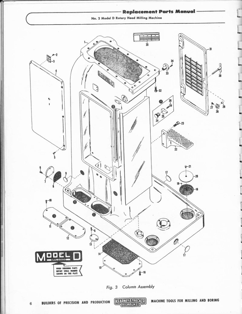
Model 2D Rotary Head Milling Machine Parts List
Replacement parts manual for the No. 2 Model D Rotary Head Milling Machine by Kearney and Trecker. Contains exploded view diagrams of the column assembly and table assembly with numbered part references. Includes detailed parts lists with part numbers, descriptions, and quantities for replacement components such as hinges, screws, covers, gaskets, plugs, screens, and control plates. Two spindle speed plate variants are listed (1750 rpm and 1425 rpm).
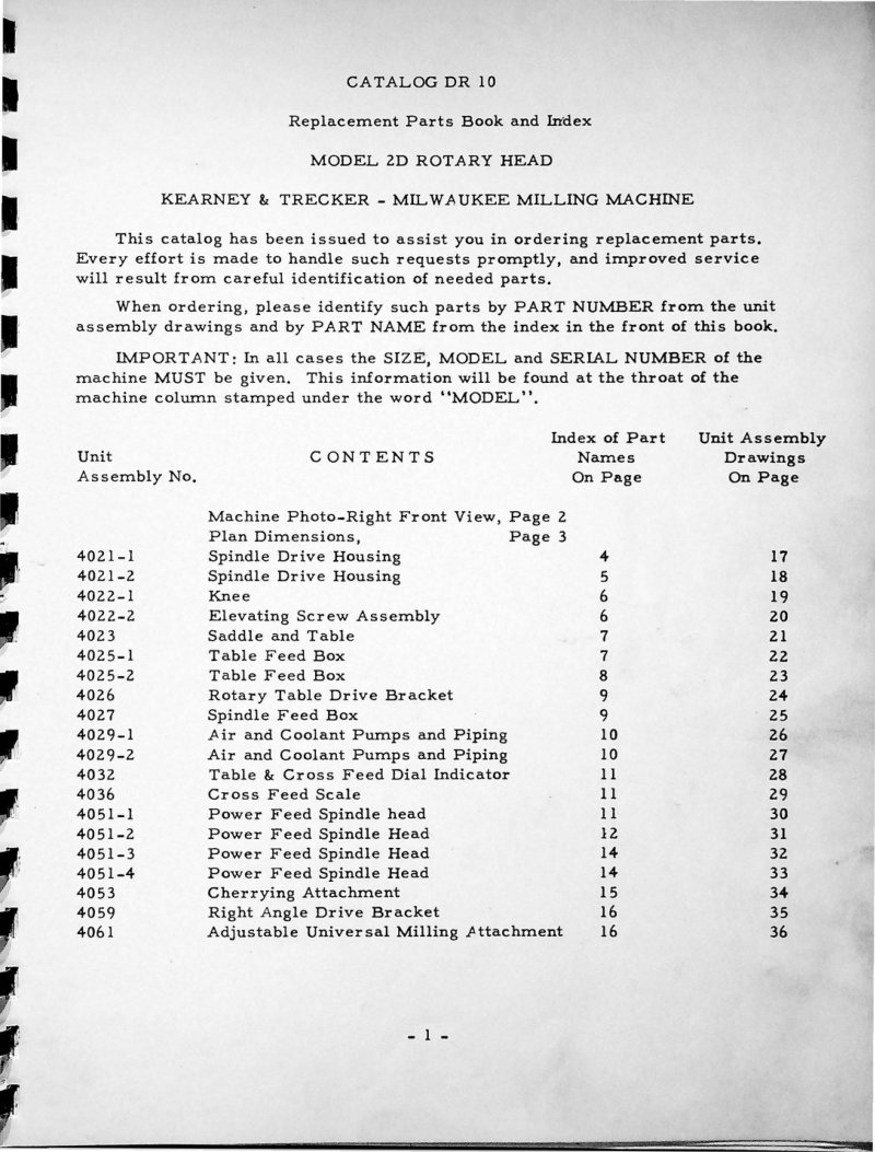
Model 2D Rotary Head Parts List
Replacement parts catalog (DR 10) for the Kearney & Trecker Model 2D Rotary Head milling machine. Contains indexed unit assembly drawings and part identification for spindle drive housing, knee, elevating screw, saddle, table, feed boxes, pumps, and various attachments. Includes machine photograph and plan dimensions.

Model 2D Wiring Diagram Schematic
Complete electrical wiring schematic for Model 2D unit. Two-page technical drawing showing circuit layouts with fused disconnect switch, bracket lamps, rotary head switch, and various electrical components including spindle drive, rotary feed, table feed, coolant pump, and air pump motors. Motor data specifications provided showing horsepower, RPM, and cycle ratings at 220/440 volts, 60 cycles. Transformer connection diagram and complete interconnected schematic with component labeling.
Model 2E Milling Machine Instruction Book
Instruction book for the Kearney & Trecker Model 2E Plain and Universal horizontal milling machine. Covers installation, electrical equipment, lubrication, coolant system, machine operation, machine adjustments, dividing head and power drive attachment. Includes hoisting procedures, foundation requirements, control identification, and speed and feed selection guides. Catalog EC 10.
Model 2E Milling Machines Repair Parts Book
Repair parts book for 3 hp Model No. 2E Plain and Universal Kearney & Trecker milling machines. Catalog ER-10, dated 1949. Covers replacement parts identification and ordering procedures with visual indexing of assemblies. Includes instructions for identifying parts by machine serial number, which must be included with all inquiries. Distributed by Fuchs Machinery & Supply Co., Omaha, Nebraska.
Model 2H Milling Machine Instruction Manual
Instruction book for Milwaukee Model 2H Plain, Universal and Vertical milling machines by Kearney & Trecker Corporation. Covers operation, lubrication and adjustment including unpacking, shortages inspection, hoisting procedures for horizontal and vertical machines, placement on foundation, leveling, cleaning and maintenance procedures. Includes specific R.P.M. and rotation direction guidelines.
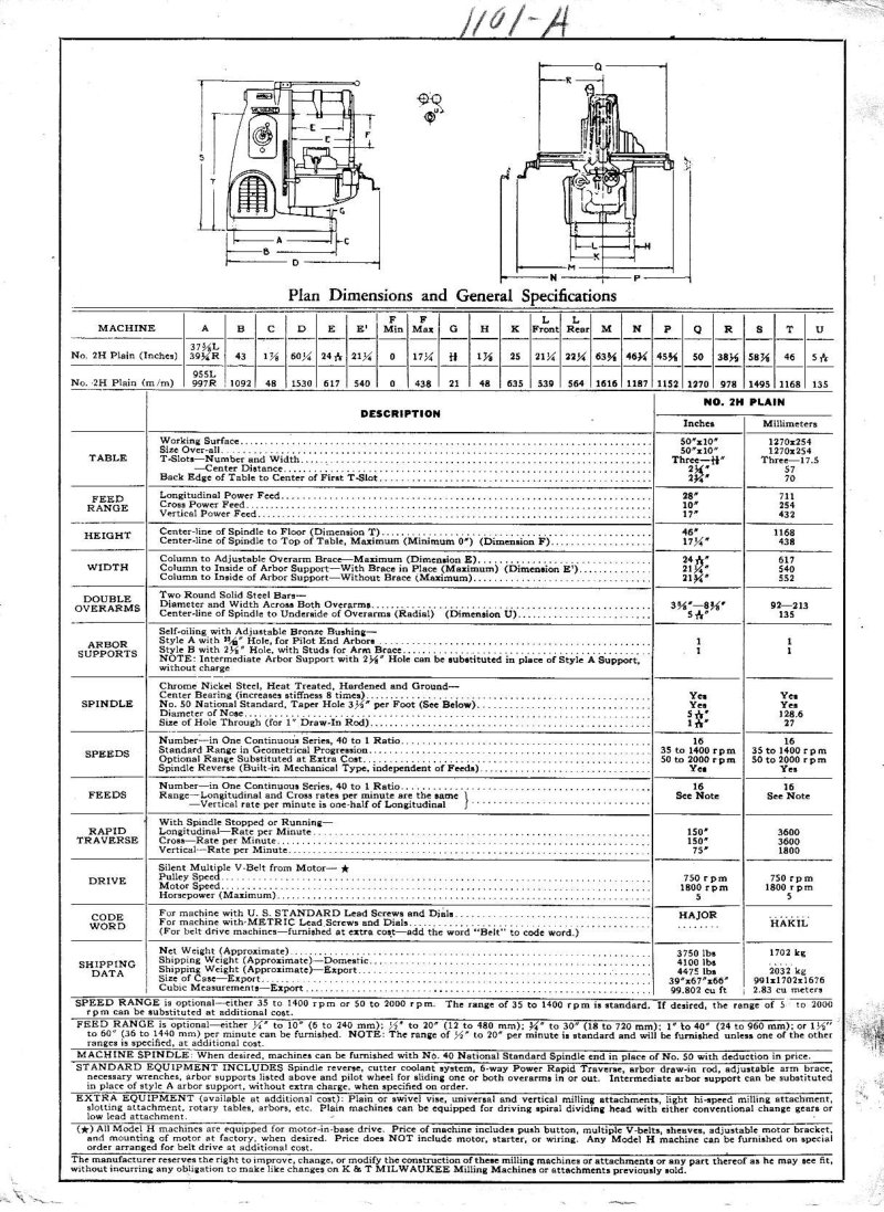
Model 2H Plain & Universal Parts List
Replacement parts book and index for Milwaukee Model 2H Plain and Universal horizontal milling machines. Catalog HR 14 from Kearney & Trecker. Contains machine photography, plan dimensions with detailed specifications, parts index with assembly numbers and drawings. Includes dimensions for table (50 inches x 10 inches), feed range details, height specifications (46 inches center-line of spindle to floor), width measurements, double overarms specifications, arbor supports, spindle characteristics, speeds (35 to 1400 rpm standard), feeds information, rapid traverse capabilities (150 inches per minute longitudinal, 75 inches per minute vertical), drive specifications, and shipping data. Table of Contents: - 1/4 inches x 1-3/16 inches long pin - Sight oil flow gauge - Oil flow gauge plate - Oil gauge plate - Oil gauge glass - Starting lever - Starting lever cover - Column - Overarm clamp - Starting lever shaft - Overarm pinion shaft - Overarm shaft bushing - Overarm shaft bushing - Overarm clutch sleeve - Overarm pinion left hand - Overarm rack - Overarm - Overarm pinion right hand - Overarm handwheel - Column vent baffle plate (inner) - Column vent baffle plate (outer) - Column vent and name plate - Column vent and name plate
Model 4K Milling Machine Operator's Manual
Operator's manual for Kearney & Trecker Model 4K plain, universal and vertical milling machines. Includes instructions for mono-lever control operation, table handwheel engagement, conventional table operation, and automatic table cycles with adjustable stop, rate and reverse dogs. Document No. KC-13.
Model 4K Vertical Milling Machine Repair Parts
Repair parts book for Milwaukee Model K Vertical knee-type milling machines. Contains unit assembly line drawings and part numbers for ordering repair parts. Lists 14 unit assemblies including adjustable vertical head, vertical column, coolant pump, cross feed bracket, feed and R.T. drive bracket, feed and R.T. take off bracket, feed gear train and distance box, start mechanism and elevator screw assembly, pulley bracket, rear control bracket, plain saddle and table, speed gear box, and vertical head power feed bracket.
Model 5H Plain and Universal Milling Machine Parts List
Replacement parts manual for the Kearney & Trecker Model 5H plain and universal milling machine. Includes illustrated parts assembly line drawings with part numbers and identifying repair parts.
Model 5H Replacement Parts Manual HR-17
Replacement parts manual for Kearney & Trecker Model 5H plain and universal milling machine. Contains unit assembly line drawings with part numbers for knee type machines, including part numbers for tailstock, spiral dividing head, column, coolant pump, feed bracket, drive bracket, gear train, saddle, speed gear box, change gear box and other components. Document No. HR-17.
Model 8 Single Spindle Automatic Parts List
Replacement parts manual for CVA Model 8 Single Spindle Automatic machine. Publication No. PD 1111. Includes detailed exploded diagrams of the backshaft assembly with numbered components and part references. Manufactured by Kearney & Trecker - C.V.A. Limited, Hove, Sussex, England. Appendix contains repair parts catalogue for serial numbers 83925 onwards. Table of Contents: - Pin - Backshaft Handwheel - Bearing Cap - Bearing Cap - Bearing Cap - Oilite Bush - Sliding Turret Clutch - Turret Clutch Pinion - Handwheel Handle - Key - Key - Chucking Gear - Chucking Clutch - Chucking Clutch (⅜ rev) - Clutch Insert (½-1 rev) - Chuck & Turret Clutch - Fixed Rev. Clutch - Rev. Cam Bush - Backshaft Bearing - Retaining Nut - Cotter Pin - Thrust Washer - Change Gear Spindle - Change Gear Bush - Change Gear Washer - Retaining Collar - Spring Plunger - Retaining Pin - Cam Stop Pin - Pin - Pin - Pin - Pin - Clutch Spring - Ret. Collar Spring - Socket Cap Screw ⅜BSFS x ⅞" - Socket Cap Screw 2BA x ⅜" - Socket Cap Screw 4BA x ⅜" - Hex Nut ⅜" BSF - Oiler - Treasure Spring Lid
Model AC, 18CH, 24CH Replacement Parts Manual
Replacement parts manual for Kearney & Trecker 3hp vertical milling machines. Covers Model AC (18 and 24 inches, plain and swivel head with mono-lever and automatic cycle table control), Model CH (3hp No. 1, plain-universal-swivel head with standard directional table control), and Model CHL (3hp No. 2). Includes indexed assemblies with visual parts identification and ordering instructions based on machine serial number. Table of Contents: - Vertical Column Speed Drive Train and Motor Mount - Swivel Head and Spindle - Speed Gear Box - Table - Plain Saddle and Cross Feed Bracket - Swivel Block Coolant Return and Universal Saddle - Knee - Feed Distribution Box Feed Selection and Directional Control Levers - Feed Distribution Box Gear Trains
Model AC, CH & CHL Milling Machines Owner's Manual
Operator's manual for Kearney & Trecker 3hp and 5hp vertical milling machines. Covers plain and swivel head models AC, CH, CHL, and 18-24 inch AC machines with mono-lever and automatic cycle table control. Includes sections on electrical system, lubrication system, coolant system, conventional operation (spindle control, rapid traverse, clamps, micrometer stops), automatic cycle operation (plain, intermittent, continuous cycles), and speed and feed charts.
Model B Autometric Boring Machine Owner's Manual
Operator's instruction manual for the Milwaukee Kearney & Trecker Model B Autometric Precision Boring Machine. Catalog No. BAC-12. The document covers precision boring practice and operational procedures for this automated precision boring machine.
Model B Autometric Jig Boring Machine Manual
Instruction book for the Milwaukee Model B Autometric Jig Boring Machine by Kearney & Trecker Products Corporation. Covers installation, lubrication, and operation including uncrating, shortages verification, hoisting procedures, machine location and environmental requirements (air-conditioned room, 70°F uniform temperature, solid vibration-free floor), leveling with three steel leveling plates and leveling screws with lock nuts, and cleaning procedures with kerosene and hand lubrication of sliding members.
Model B Autometric Precision Boring Machine Parts Manual
Replacement parts manual for the Kearney & Trecker Model B Autometric Precision Boring Machine. Catalog No. BAR-11. Published by Kearney & Trecker Corporation, Milwaukee, Wisconsin. Copyright 1953. One copy furnished with each new machine; additional copies available from the manufacturer. Price: $3.00.
Model C Autometric Boring Machines Maintenance and Parts Manual
Maintenance and replacement parts manual for Kearney & Trecker Model C Autometric No. 2 and No. 3 precision vertical boring machines. Includes assembly diagrams indexed visually on page 12, detailed instructions for identifying and ordering replacement parts, serial number information, and maintenance procedures. Published by Kearney & Trecker Corporation, Milwaukee 14, Wisconsin. Copyright 1949.
Model CE Milling Machines Installation Manual
Installation manual for Kearney & Trecker Milwaukee Model CE plain and universal milling machines, 3 hp No. 2 and 7.5 hp No. 3. Covers uncrating, location selection, leveling, table assembly, table bracket assembly for both 2CE and 3CE machines, lead screw thrust bearing adjustment, table gib adjustment, electrical connections, and pulley belt installation. Includes hoisting specifications (3300-3500 lbs for 2CE, 4000-6400 lbs for 3CE), lubrication chart, and plan dimensions.
Model CE Milling Machines Operator's Manual
Operator's manual for Kearney & Trecker Model CE plain and universal milling machines, 3hp No. 2 and 7.5hp No. 3 models. Covers electrical system, lubrication system, coolant system, conventional operation including spindle reverse control, speed change control, coolant pump control, power feed controls, hand feed controls, micrometer dials, and feed change control. Includes machine adjustments for saddle gib, knee gib, table gib, table screw thrust bearings, pulley belt, and arbor bearing adjustment. Features preventive maintenance section with lubrication chart, plan dimensions, effective cutting areas, and rules for determining correct speeds and feeds.
Model CE Plain and Universal Milling Machines Parts List
Replacement parts manual No. CER-3 for the 3hp No. 2 Model CE plain and universal milling machines manufactured by Kearney & Trecker Corporation. Published 1956. Manual provides indexed assemblies for parts identification and ordering. Includes instructions for identifying and ordering parts with machine serial number information.
Model CH 5hp No.2 Milling Machines Parts List
Replacement parts manual for Kearney & Trecker 5hp No. 2 Model CH Plain, Universal and Vertical milling machines, with mono-lever and automatic cycle table control, or with standard directional control. Published 1951. Catalog No. CHR-33. Includes indexed assembly diagrams and parts identification for complete machine maintenance and repair.
Model CH Milling Machine Replacement Parts Manual
Replacement parts manual for Kearney and Trecker Model CH plain, universal and vertical milling machines. Covers 7.5 hp No. 3 and 10 hp No. 4 models with standard directional table control and mono-lever automatic cycle table control. Published by Kearney and Trecker Corporation, Milwaukee, Wisconsin. Copyright 1951. Catalog No. CHR-35. Table of Contents: - Coolant Supply System, Style B Arbor Support and Arm Brace - Intermediate Style Arbor Support and Style A Arbor Support - Horizontal Column Starting Lever - Horizontal Column Spindle Assembly - Horizontal Column Motor Mount - Tailstock, Steadyrest and Conventional Lead Attachment - Low Lead Attachment - Dividing Head - Speed Gear Box Assembly - Vertical Column Left Side - Table Assemblies - Plain Saddle and Cross Feed Bracket Assemblies - Automatic Cycle Saddle and Hydraulic Valve Body Assemblies - Universal Saddle Assembly - Universal Swivel Block Assembly
Model CH Milling Machines Parts Manual
Replacement parts manual for Kearney & Trecker 7.5 hp No. 3 and 10 hp No. 4 Model CH plain, universal and vertical milling machines. Manual includes assemblies arranged in natural sequence with visual indexing on pages 4 and 5. Covers machines with mono-lever automatic cycle table control and standard directional table control. Information for ordering includes machine size, model and serial number stamped in lower border of trademark on column.
Model CK Milling Machine Replacement Parts Manual
Replacement parts manual for 10hp No. 2 and 15hp No. 3 Kearney & Trecker Model CK Plain, Universal and Vertical milling machines. Covers machines with standard directional table control and mono-lever automatic cycle table control. Published by Kearney & Trecker Corporation, Milwaukee 14, Wisconsin. Copyright 1951. Table of Contents: - Vertical Head Assembly - Head Power Feed Bracket Assembly - Pulley Bracket Assembly - Feed and Rapid Traverse Drive Bracket Assembly - Automatic Cycle Feed and Rapid Traverse Drive Bracket Assembly - Knee Assembly Rear Controls - Gear Trains - Miscellaneous Parts - Feed Distribution Box Assembly - Vertical Column Right Side
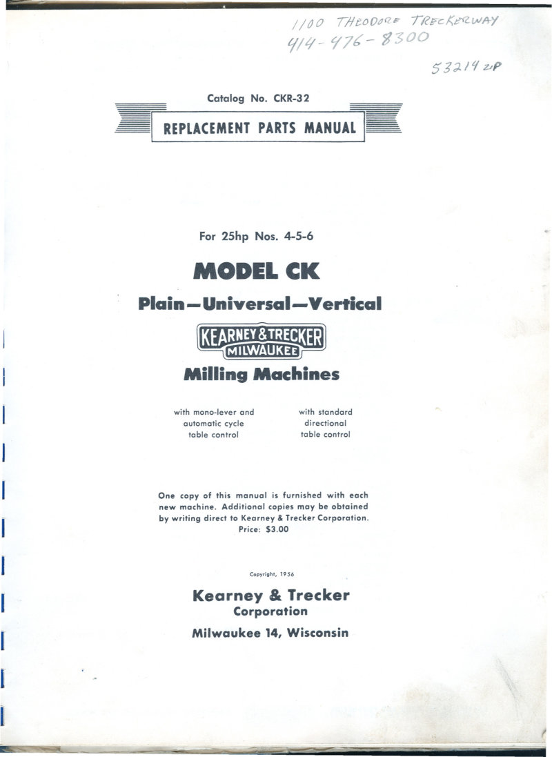
Model CK Milling Machines Parts List
Replacement parts manual for Kearney & Trecker Model CK 25hp plain, universal and vertical milling machines (models 4, 5, 6). Covers machines with standard directional table control and mono-lever automatic cycle table control. Published by Kearney & Trecker Corporation, Milwaukee, Wisconsin. Copyright 1956.

Model CK Milling Machines Parts Manual
Replacement parts manual for Kearney & Trecker Model CK Plain, Universal and Vertical milling machines (10hp No. 2 and 15hp No. 3). Covers machines with standard directional table control and mono-lever automatic cycle table control. Published 1951, Catalog No. CKR-30.
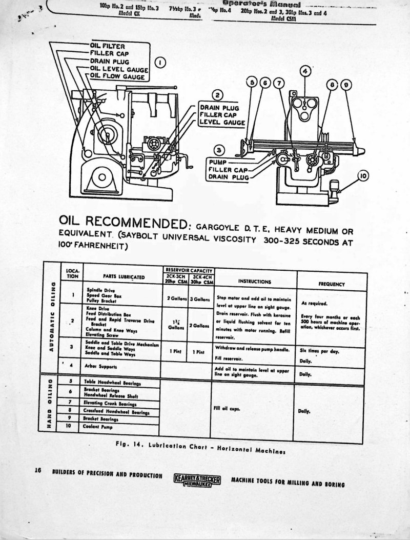
Model CK No. 2 & 3 Horizontal Mill Operator's Manual
Operator's manual for Kearney & Trecker Model CK horizontal milling machines (No. 2 and No. 3). Contains lubrication charts for horizontal and vertical machines with detailed diagrams showing oil filter, filler cap, drain plug, oil level gauge locations, and oil flow gauges. Specifies recommended oil (Gargoyle D.T.E. Heavy Medium, Saybolt universal viscosity 300-325 seconds at 100 degrees Fahrenheit). Lubrication instructions for automatic and hand oiling locations with maintenance frequencies (as required, every four months, six times per day, daily). Includes reservoir capacity data and parts lubrication requirements for spindle drive, speed gear box, pulleys, feed drive, broaching mechanisms, bearings, and coolant pump.
Model CSM Nos. 4-5-6 Replacement Parts Manual
Replacement parts manual for Kearney & Trecker Model CSM plain and vertical milling machines, Numbers 4, 5 and 6. Includes parts identification indexed on pages 4 and 5 (Figs. 1 and 2). Available with mono-lever and automatic cycle table control or with standard directional table control. Published 1956. Document includes foreword explaining part ordering procedures and serial number requirements for efficient service. Table of Contents: - Spindle draw bolt head - Taper pin, #1/4 x 1-1/4 in. - Draw bolt nut - Socket draw-in bolt - Fill nut screw, 5/16-18 x 3 in. - Screw, 5/16-18 x 7/8 in. - Flywheel cover - Collar nut screw, 3/8-24 x 3/8 in. - Collar nut shoe - Blue label dowel, 5/8 x 2-1/4 in. - Collar nut - Soc hd cap screw, 5/8 x 1-1/2 in. - Flywheel drive ring - Flywheel - Snap ring, #51-287 - Filling washer - Timken bearing, 563-567 - Spindle center bearing spacer - Snap ring - Spindle onut nut - Spindle nut sleeve - Spindle gear collar - Headless dowel screw, 3/8-16 x 9/16 in. - Timken bearing, 752V-757W - Collar nut screw - Collar nut shoe - Collar nut - Small spindle gear - Large spindle gear - Timken bearing, 854B-866 - Spindle - Spindle drive key - Bearing retainer screw, 3/8-16 x 13/16 in. - Spindle drive key - Spindle key screw, 7/16-14 x 1-1/8 in. - Spindle oil shield - Spindle oil shield screw, 5/16-18 x 2-5/16 in. - Soc hd mach screw, 3/8-16 x 3/4 in. - Spindle drive shaft bearing retainer - Primary change shaft bearing spacer - Timken bearing, 652A-655 - Spindle drive shaft - Primary low speed sliding gear - Primary high speed sliding gear - Timken bearing, 552B-555 - Snap ring - Spindle drive gear - Spindle drive pinion - Hyatt bearing, 313HS - Primary shaft bearing spacer - Spindle drive pinion bearing sleeve - Spindle drive shaft bearing cover - Spindle drive shaft bearing cover stud - Washer - Hex nut, 3/8-16 - Range shifter fork - Range shifter fork rod - Horizontal column
Model D Rotary Head Mill Parts List
Replacement parts manual for Kearney & Trecker No. 2 Model D rotary head milling machine. Catalog DR-20, copyright 1954. Contains parts identification and availability information. One copy furnished with each new machine.
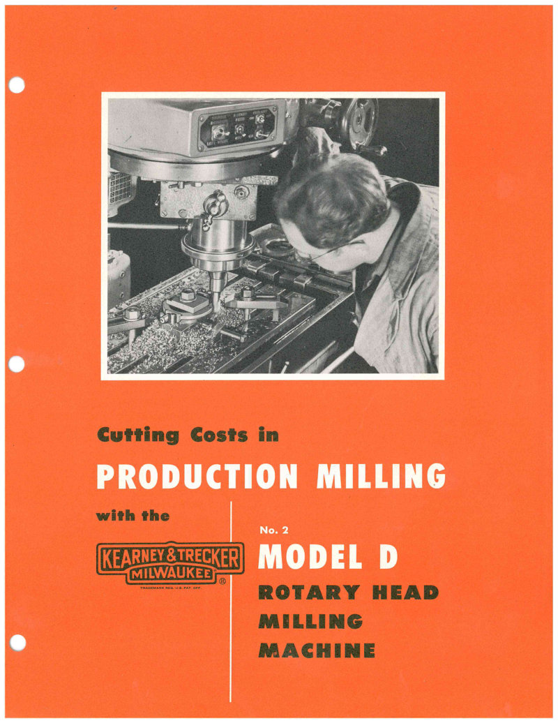
Model D Rotary Head Milling - Technical Data
Technical documentation for the Kearney & Trecker Model 2D Rotary Head milling machine. Contains production case studies demonstrating cost reduction and cycle time improvements. Includes operation procedures for rough milling, finish milling, and angled cuts on shift levers and control valve levers. Production data shows cycle time reduction from 3.5 minutes to 45-50 seconds for shift lever operations and from 24 minutes to 17 minutes for control valve lever operations. Features technical drawings, dimensional specifications, and setup procedures.
Model F Milling Machines Parts List
Repair parts catalog for Model F Milwaukee milling machines manufactured by Kearney and Trecker. Contains comprehensive parts listing for horizontal machines with part numbers and names. Includes ordering instructions referencing serial numbers up to lot 952 for No. 3 Horizontal machines and other models. Covers spindle assemblies, drive systems, clutch mechanisms, pumps, and support structures.
Model F Milwaukee Milling Machines Parts List
Repair parts list for Model F Milwaukee Milling Machines. Covers horizontal and vertical machine sizes (No. 1 through No. 4 horizontal; No. 1 through No. 4 vertical). Includes detailed parts numbering with serial number references up to 890-1058 depending on machine size and orientation. Contains instructions for ordering parts with serial number and machine size specifications.
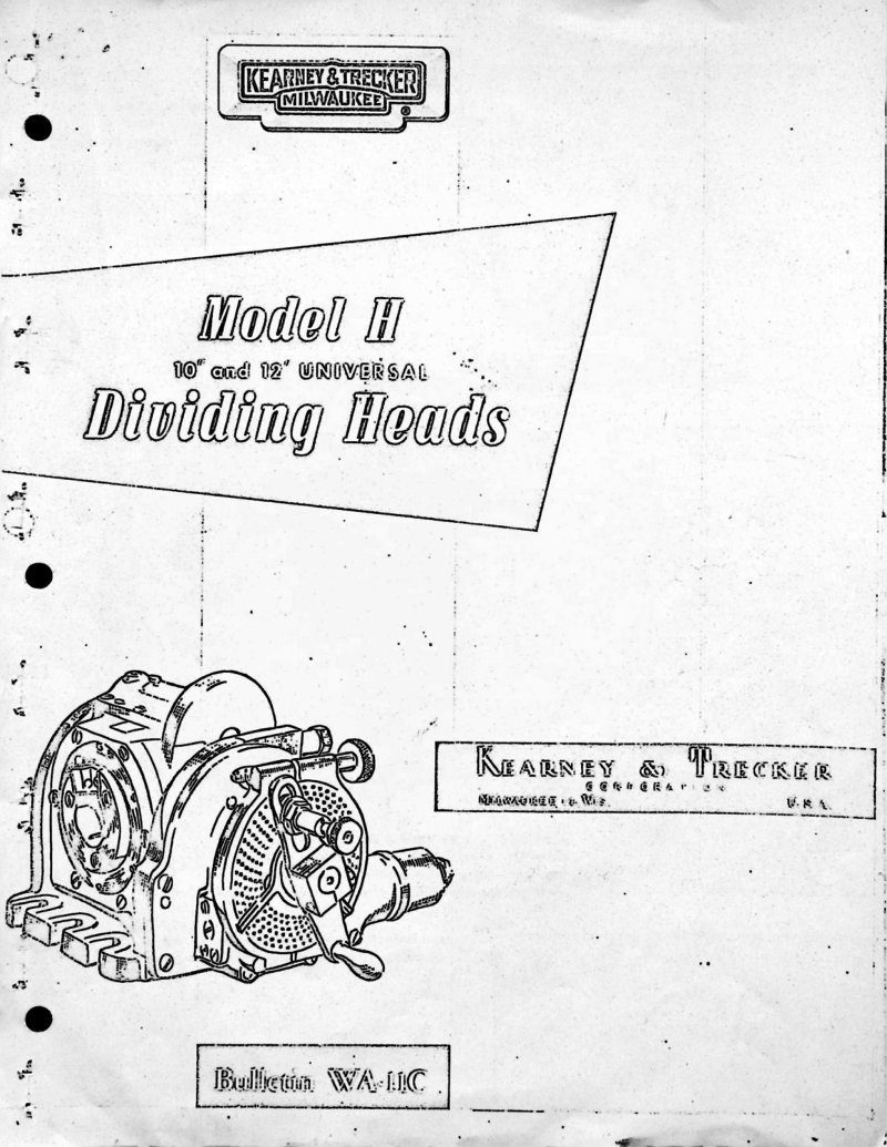
Model H 10 & 12 Dividing Heads Service Manual
Operations and parts manual for Kearney & Trecker Model H Universal Dividing Heads in 10 inches and 12 inches. Covers clamping methods, lead cutting operations with conventional and low lead attachments, indexing systems including the Compudex automatic indexer, maintenance and lubrication procedures. Includes detailed technical information on index cranks and plates, worm gearing construction, and circular milling operations.
Model H Milling Machine Parts List
Replacement parts manual for 5 hp No. 2 Model H Plain-Universal-Vertical-Automatic Cycle Milling Machines manufactured by Kearney & Trecker Corporation, Milwaukee. Includes identification procedures for locating assemblies, exploded views with item numbering, and instructions for ordering replacement parts with machine size, model, and serial number references.
Model H Milling Machine Parts Manual
Replacement parts manual for Kearney & Trecker 7.5hp No. 3 and 10hp No. 4 Model H plain, universal and vertical milling machines. Covers both standard directional table control and mono-lever automatic cycle table control variants. Published 1955. Instructions for identifying and ordering parts based on machine serial numbers.
Model H Milling Machine Replacement Parts Manual
Replacement parts manual for Kearney & Trecker Model H plain-universal-vertical milling machines. Covers Models 2 and 3 KM with 7.5 hp No. 3 and 10 hp No. 4 motors. Includes versions with standard directional table control and mono-lever automatic cycle table control. Published 1955.
Model H Milling Machine Replacement Parts Manual
Replacement parts manual for the Kearney & Trecker Model H Plain, Universal and Vertical milling machines in 7.5 hp No. 3 and 10 hp No. 4 versions. Includes parts listings for machines with mono-lever automatic cycle table control and standard directional table control. Published by Kearney & Trecker Corporation, Milwaukee, Wisconsin in 1955. Contains visual index of assemblies on pages 4 and 5, with instructions for identifying and ordering parts by machine serial number. Table of Contents: - Range change fork - Range change shifter rod - Filler plug - Allen cap screw - Washer - Filler head - Filler hd gasket - Cuno 100 disc unit cartridge - Ball retainer - Filler screw - Expansion plug - Motor door - Motor door hinge - Socket screw - Hex cap screw - Lockwasher - Door latch - Set screw - Door handle - Bearing washer - Electric motor - Acme blue label dowel - Coolant cleanout cover - Pipe gasket - Coolant drain screw - Flat hd screw - Coolant drain cover - Wiper plug - Pipe cap - Columm - Pulley door - Pulley door hinge - Hex hd screw - Lockwasher - Door latch - Set screw - Door handle - Spacing washer - Casing screw - Coolant pipe guard - Hex hd screw - Gilts oiler - Stud - Clamp block pin - Spring - Overarm clamp - Washer - Hex nut - Hex nut - Overarm handwheel - Taper pin - Taper pin - Headless dowel screw - Overarm shaft bushing - Overarm pinion shaft - Overarm pinion - Overarm clutch sleeve - Nut - Overarm pinion - Overarm shaft bushing - Cross and elevating trip dog - Cross and elevating trip dog - Trip dog screw - Hex nut - Oval hd screw - Oil gauge plate - Oil gauge glass - Oil gauge washer - Oil gauge plate - Oil flow gauge - Starting lever stand pipe - Hi-Pro key - Starting lever shaft - Pipe gasket - Starting lever cap - Starting lever stop pin - Starting lever - Fill hd screw - Starting lever cover - Fill hd screw - Cutler-Hammer starting switch - Spindle - Spindle drive key - Fill hd screw - Spindle oil shield - Fill hd screw - Fill hd screw - Timken bearing - Large spindle gear - Small spindle gear - Collar nut - Collar nut shoe - Soc set screw - Soc set screw
Model H Milling Machines Operator's Manual
Operator's manual for Kearney & Trecker Model 3H and 4H plain, universal and vertical milling machines. Publication No. 83. Covers 7.5 hp No. 3 and 10 hp No. 4 models. Contains sections on uncrating, shortages verification, hoisting procedures, foundation placement, machine leveling, cleaning, overarm adjustments, pulley speed settings, motor positioning, and drive belt adjustment. Machine weight: 9000 lbs.
Model H Milling Machines Operator's Manual
Operator's manual for Kearney & Trecker Milwaukee Model H plain, universal and vertical milling machines (7.5 HP No. 3 and 10 HP No. 4). Covers operation, lubrication and adjustment including uncrating, hoisting, foundation placement, machine leveling, cleaning, overarm operation, pulley speed settings, motor installation, and belt drive adjustment.
Model H Milling Machines Parts List
Replacement parts manual for Kearney & Trecker Model H Plain, Universal and Vertical milling machines. Covers 7.5 hp No. 3 and 10 hp No. 4 models with standard directional table control and mono-lever automatic cycle table control. Published 1955.
Model K Dividing Head Operator's Manual
Operator's manual for the Kearney & Trecker Model K Universal Spiral Dividing Head with conventional and low lead attachments. Contains operating instructions, tables of leads and indexing divisions for milling machines equipped with U.S. Standard lead screw. Includes sections on spindle, index crank and plunger, hand drive, tail stock, steady rest, right angle drive bracket, index plates, lubrication, and astronomical divider. Published 1952.
Model K Milling Machine Replacement Parts
Replacement parts manual for Kearney & Trecker Model K Plain, Universal and Vertical milling machines, 7.5 hp No. 2 and 10 hp No. 3 models. Covers both standard directional table control and mono-lever automatic cycle table control variants. Published 1950. Includes visual indexing of assemblies and instructions for identifying and ordering parts by machine serial number.
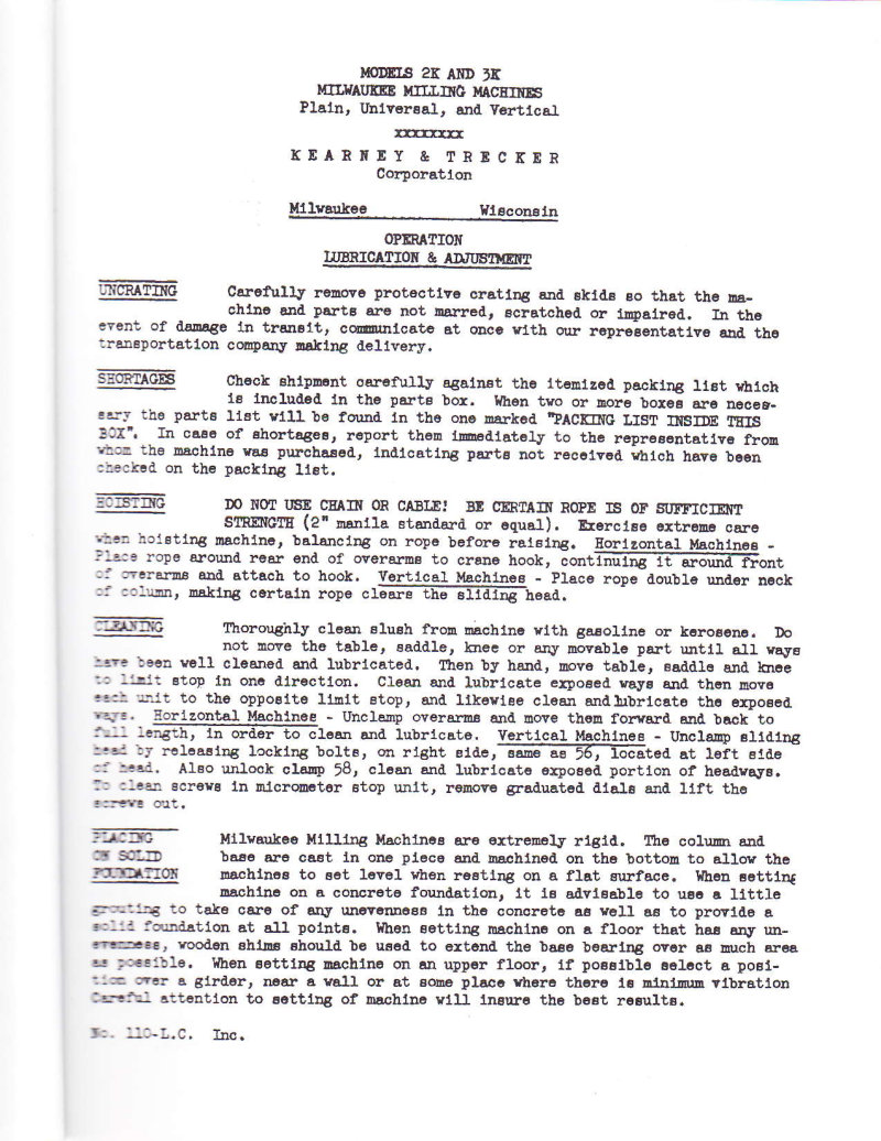
Model K Milling Machines Operator's Manual
Operator's manual for Kearney & Trecker Model K plain, universal and vertical milling machines (7.5 hp No. 2 and 10 hp No. 3). Covers uncrating, inspection for shortages, hoisting procedures, cleaning and lubrication, leveling, motor and belt drive installation, speed and rotation direction, and column lubrication system with central lubricant reservoir using D.T.F. oil heavy medium.
Model K Milling Machines Operator's Manual
Operator's manual No. KC-11 for Kearney & Trecker Milwaukee Model K plain, universal, and vertical milling machines. Covers 7.5 hp No. 2 and 10 hp No. 3 models. Includes sections on uncrating, shortages, hoisting, cleaning, placing on foundation, leveling, motor or belt drive setup, speed of sheave and rotation direction, motor placement and belt adjustment, lubrication procedures, and column lubrication system details with reservoir specifications.
Model K Milling Machines Replacement Parts Manual
Replacement parts manual for Kearney & Trecker Model K Plain, Universal and Vertical milling machines (7.5 hp No. 2 and 10 hp No. 3). Catalog No. KR-20. Includes information for machines with both mono-lever/automatic cycle table control and standard directional table control. Published 1950. Covers identification and ordering of replacement parts with visual index of assemblies.
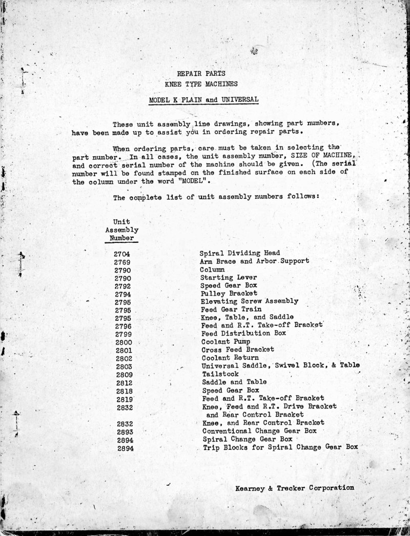
Model K Plain & Universal Repair Parts List
Repair parts list for Kearney & Trecker Model K Plain and Universal knee type milling machines. Includes unit assembly numbers (2704-2894) with part identification and descriptions. Contains dimensional drawings, plan dimensions with detailed specifications in inches and millimeters, and general specifications for 2K Plain and 3K Plain Milwaukee milling machines. Lists table surfaces, feed ranges, spindle specifications with 24 speeds from 15 to 1500 r.p.m., rapid traverse capabilities, and shipping specifications.
Model K Universal Spiral Dividing Head Operator Manual
Operating manual for the Model K Universal Spiral Dividing Head with Conventional and Low Lead Attachments for Kearney and Trecker milling machines equipped with U.S. Standard Lead Screw. Includes operating instructions for spindle, index crank and plunger, hand drive, tail stock, steady rest, right angle drive bracket, and astronomical divider. Contains tables of leads and indexing divisions for both conventional and low lead attachments, plus thread milling information. 47 pages total.
Model K Universal Spiral Dividing Head Operator's Manual
Operator's manual for the Kearney & Trecker Model K Universal Spiral Dividing Head. Contains plain and differential indexing table with formulas for indexing calculations. Includes standard equipment specifications with index plate hole configurations (100-96-92-84-72-66-60 holes on one side, 98-88-78-76-68-58-54 holes on reverse) and standard gear sets with 20 teeth and various tooth counts from 21 to 40. Includes technical diagrams showing the dividing head assembly with indexing mechanism and gear train components.
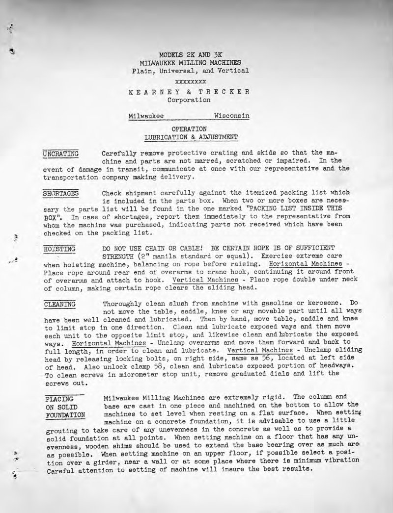
Models 2K & 3K Milling Machines Instruction Manual
Instruction manual for Milwaukee Models 2K and 3K Plain, Universal, and Vertical Milling Machines by Kearney & Trecker. Covers uncrating, cleaning, hoisting, foundation placement, leveling, motor or belt drive setup, sheave speed and rotation, motor installation, belt adjustment, and lubrication procedures including central column lubrication system with reservoir and flood distribution.
Modu-Line HMC KT-Gemini D-17 Programming Manual
Programming and operating manual for the Kearney & Trecker Traveling Column Modu-Line machining center with KT-Gemini D-17 control system. Includes safety guidelines and operational procedures for this metal cutting machine tool. Table of Contents: - Machine and Control Description - Basic Machine Description - Machine Control Unit - Standard Control Features - Modes of Operation - Optional Control Features - Power Distribution Panel - Hydraulic Power Supply - Traveling Column Style Modu-Line Machining Center with Pallet Work Surface and Shuttle Mechanism - Introduction - Zero Reference Positions - Standard Grid Positions - Collision Zones - Table Units - Description - Operation - Pallets - Z Prime Slide - Description - Operation - Pallet Shuttle System - General Description - Operation, Side Loading Shuttle - Shuttle Station Controls - Manual Shuttle Operation - Spindle Head Unit - Machine Features - Automatic Tool Changer and Tool Magazine - Description - Tool Select Commands - Tool Codes (Octal) - Tool Codes (Decimal) - Automatic Tool Transfer Command - Manual Tool Transfer Programming - Use of Keyed Tools (Straight Shank) - General - Keylock Orientation - Remote Control Station - Emergency Stop - Cycle Start - Cycle Stop - Magazine Manual/Auto
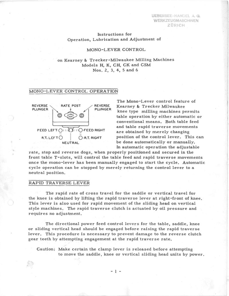
Mono-Lever Control Operator's Manual
Instructions for operation, lubrication and adjustment of the Mono-Lever control system on Kearney & Trecker-Milwaukee milling machines, models H, K, CH, CK and CSM numbers 2, 3, 4, 5 and 6. Covers automatic and conventional table operation modes, rapid traverse lever operation, table handwheel engagement, and automatic table cycle arrangements including plain cycles with rapid traverse return and intermittent cycles with rapid traverse return. Details the functions of adjustable stop dogs, rate dogs, and reverse dogs for automatic table operation.
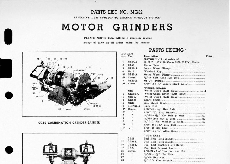
Motor Grinders Parts List
Parts list for Walker-Turner motor grinder models including CG50 combination grinder-sander, GR50 1/2 H.P. motor grinder, and GR35-36 1/3 H.P. motor grinders. Contains numbered parts listings with part numbers, descriptions, and exploded view diagrams for motor units, wheel guards, tool rests, cooling cups, eye shields, sanding disc assemblies, and pedestal stands. Effective January 1, 1949.
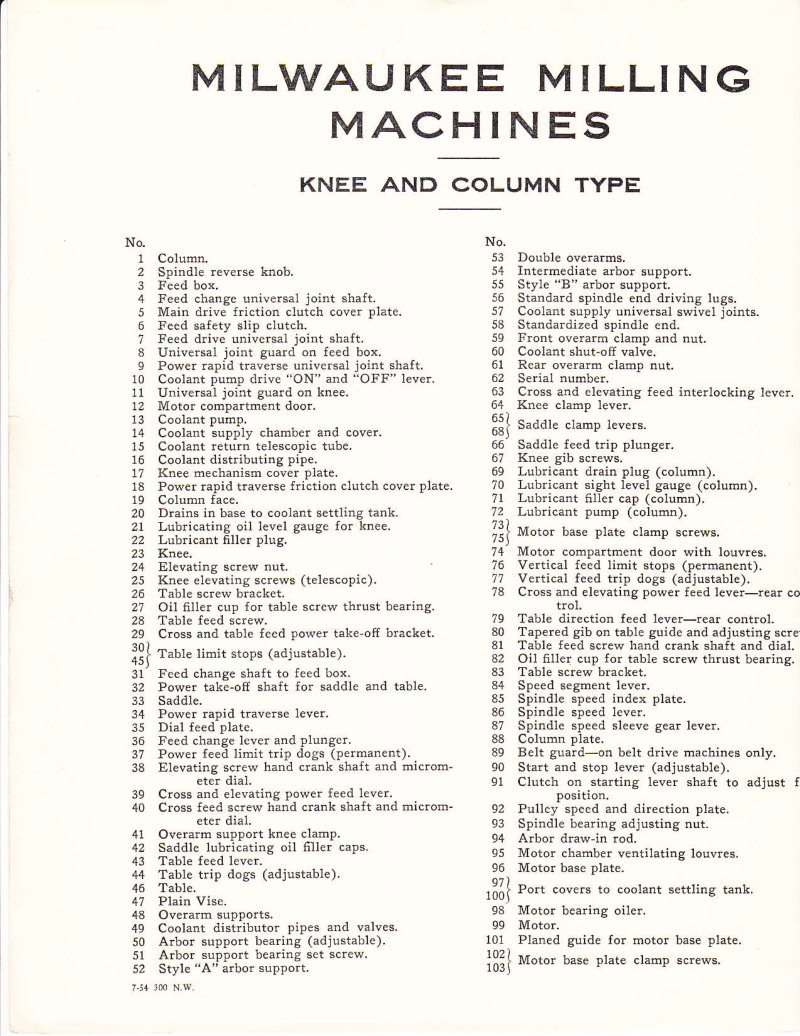
No. 1 & 2 Special Milling Machines Operator's Manual
Operator's manual for Kearney & Trecker Milwaukee knee and column type milling machines, models No. 1 and No. 2 Special horizontal and vertical milling machines. Includes comprehensive parts identification diagrams with 103 numbered components covering the spindle, feed systems, table mechanisms, coolant system, and motor compartment. Detailed schematic views of the machine from multiple angles showing all major assemblies and control features.
No. 1 and 2K Milling Machine Service Manual
Instructions for removal of feed and speed units and timing seeds and feeds on No. 1 and 2K Machines (1931 Model), Plain-Universal-Vertical Letter Machines with 26 inch P.M. feed setting. Contains detailed step-by-step procedures for removing speed box from column, dismantling feed gear train, and removing speed gear train from box, including reference to associated component assemblies and print numbers.
Orion 2300 Machining Center Programming Manual
Part programming and operating manual supplement for the Orion 2300 Machining Center with KT-GEMINI-D machine control system. Preliminary information publication from Kearney & Trecker Corporation. Includes safety guidelines emphasizing that safety is everybody's business. Table of Contents: - The employer is responsible for selecting competent and qualified employees - Manuals are provided with each machine tool - Guards and shields are to be in place at all times - Operators must be forbidden from changing workpieces or performing other work close to a revolving cutter - When contaminants are released to the atmosphere as a result of machining, an exhaust system is recommended - All employees should be aware of first aid facilities and be encouraged to use same - Employees should be encouraged to report any hazardous condition on the machine tool or in the immediate area - Air hoses must not be available for use around the machine tool - Levels of illumination in the immediate area of the machine tool should comply with National Standards - Fire prevention must be practiced and fire protection available to prevent loss of life, personal injury and to protect property - Protective footwear affords good protection against rolling objects, dropping heavy objects, accidentally kicking sharp edged materials - Eye protection devices must be considered as optical instruments and should be carefully selected, fitted and used - The employer must insist that his employees study this safety information and practice safety - Users must have available adequate lifting facilities capable of lifting within the safe load limits - Every floor opening resulting from the machine tool installed in pits or below floor level should be covered with a material of proper strength with non-slip features - When machines are installed above floor level and a platform is built around the machine tool, the platform must be constructed of materials of proper strength with non-slip features - Management personnel have the responsibility to alert operating personnel of any unsafe practice they may observe
Production Analysis Data Manual and Kwikrate Methods
Production analysis manual for Milwaukee-Matic machine tools covering manual and Kwikrate methods for production data analysis. Document PAD-66 from Kearney & Trecker Corporation. Includes service update record tracking system with instructions for sequential numbering and update processing.
PUB 298A Tool Setter Installation Manual
Installation and replacement parts manual for the PUB 298A (formerly TSI-66) Tool Setter, a Milwaukee-Matic precision optical/digital readout system by Kearney & Trecker Corporation. Document includes labeled technical diagram of the Vernac Scale Tool Setter showing major components including Vernac readers, hydraulic chucks, horizontal and vertical slide handwheels, bevel gears access, tool adjusting handwheel, pilot light, and travel limit adjusting screws. First edition October 1967, second edition September 1981.
PUB 800 Fixture Offsets Programming Manual
Programming and operating manual supplement for PUB 800 fixture offsets used with KT-Gemini machine control systems. Includes safety guidelines emphasizing that safety is everybody's business. Published by Kearney & Trecker Corporation (A Cross & Trecker Company). First edition, May 1976.
PUB 935A Multipoint Tool Sensor Manual
Operator and maintenance manual for the PUB 935A Multipoint Tool Sensor by Kearney & Trecker Corporation. Document includes safety guidelines and operational procedures. First edition from May 1978.
PUB115F Production Analysis Data Manual
Production analysis data manual for Milwaukee-Matic machine tools. Contains general instructions in both inch and metric systems, including tool clearances, drill travel, side cutting travel, and spot drilling specifications. Includes feed rate graphs for cast iron, steel, and aluminum in both inch and metric measurements. Features time positioning graph and Milwaukee-Matic time data for manual operations and various machine series including Eb, 100, VB-2, VB-4, HB-4, and 180 models. Published by Kearney & Trecker Corporation.
RAM HEAD Milling Machines Parts Manual
Replacement parts manual for Kearney & Trecker plain and universal RAM HEAD milling machines, covering models 2CH, 3CH, 4CH, and CSM series. Manual RHR-10, copyright 1956. Contains indexed assemblies and replacement parts identification with instructions for ordering. Notes cross-references to other manuals for complete machine parts (CHR-33, CHR-35, CKR-30, SMR-20).
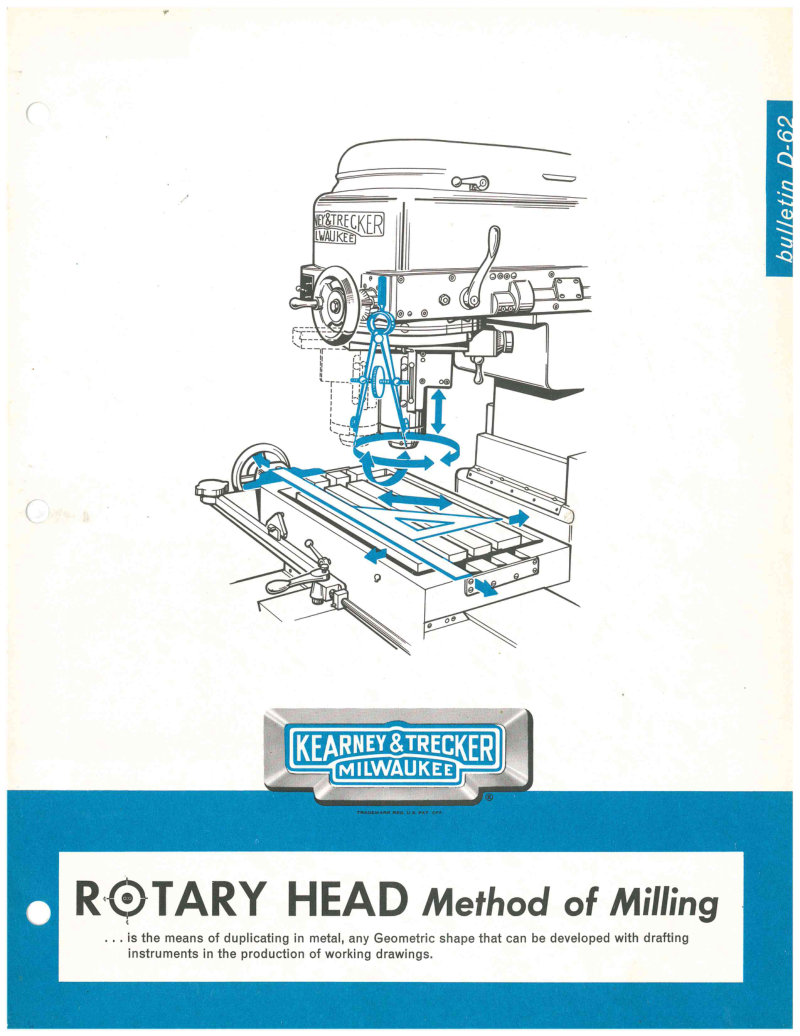
Rotary Head Milling Machine Instructions
Technical instructions for the Kearney and Trecker Model D Rotary Head milling machine. Covers the principle of rotary head milling method, mechanical control of cutting elements for straight, angular and radial movements in horizontal and vertical planes. Includes technical drawings with dimensions, setup procedures, and examples of finished workpieces. Demonstrates geometric shape duplication capabilities without templates.
Rotary Head Milling Machine Service Manual
Operating instructions for the Kearney & Trecker Milwaukee Rotary Head Milling Machine. Includes foreword explaining geometric reproduction capabilities, workpiece setup procedures, and Exercise 1 with operation data and instructions for roughing and finishing operations using a 0.500 inch diameter 2-flute cutter at 750 rpm spindle speed on mild steel with feeds of 1.5 inches per minute (table-longitudinal) and 3/8 R.P.M. (rotary head-circular).
Rotary Tables & Vises Parts Manual
Replacement parts manual for Kearney & Trecker Milwaukee milling machines. Covers rotary tables in 12, 16, 20, and 24 inches, rotary table drive brackets, adapter drive brackets, and plain and swivel vises in 5, 6, 7, 8, and 9 inches. Catalog AR-10, Copyright 1956. Includes visual indexing of assemblies and detailed instructions for ordering replacement parts with serial numbers.
Rotary Tables and Vises Parts Manual Pub. 28
Replacement parts manual for Kearney & Trecker milling machine attachments. Covers rotary tables in 12 inch, 16 inch, 20 inch, and 24 inch sizes; rotary table drive brackets; adapter drive brackets; and plain and swivel vises in 5 inch, 6 inch, 7 inch, 8 inch, and 9 inch sizes. Published 1956, price 3.00 dollars. Includes foreword and instructions for identifying and ordering parts by attachment name, serial number, and machine size.
S-12 & S-15 Knee Milling Machines Operator's Manual
Operator's Manual No. SC-64 for Kearney & Trecker S-12 and S-15 knee type milling machines. Contents include index covering machine controls, spindle operations, feed mechanisms, table movements, automatic and manual cycles, arbor systems, lubrication and coolant, machine dimensions, and electrical control switches. Includes labeled diagram of S-15 plain style milling machine showing overarm, table clamp lever, feed levers, and control elements.
S-12 and S-15 Knee Type Milling Machines Maintenance Manual
Machine maintenance manual for Kearney & Tracker Corporation S-12 and S-15 series knee type milling machines. Publication PUB 214 from August 1977. Covers plain, universal, and vertical configurations. Includes safety guidelines and operational procedures. 63 pages total. Table of Contents: - Machine Adjustments (Mechanical and Hydraulic) - Removal and Disassembly Instructions - Assembly and Installation Instructions - Lubrication Instructions - Miscellaneous Maintenance Information - Hydraulic and Electrical System Drawings
S-12 and S-15 Knee Type Milling Machines Maintenance Manual
Maintenance manual for Kearney & Trecker S-12 and S-15 series knee type milling machines (plain, universal, vertical). Published August 1977 (PUB 214). Includes safety guidelines and maintenance procedures. Personal copy marked for Fred Shute from K&T Service, John Beano. Table of Contents: - Machine Adjustments (Mechanical and Hydraulic) - Removal and Disassembly Instructions - Assembly and Installation Instructions - Lubrication Instructions - Miscellaneous Maintenance Information - Hydraulic and Electrical System Drawings
S-12 and S-15 Milling Machines Maintenance Manual
Maintenance Manual No. SM-66 (First Edition, May 1966) for Kearney & Trecker Milwaukee S-12 and S-15 Plain-Universal Vertical milling machines. Includes labeled diagram showing left front view with major components: overarm handwheel, speed selector dial, electrical control switches and cabinet, table handwheel, saddle rear power feed lever, knee rear power feed lever, rear control handcrank, automatic backlash control knob, saddle power feed lever, knee power feed lever, feed selector dial, mono-lever, table clamp lever, and control pendant. Table of Contents: - Machine Adjustments (Mechanical and Hydraulic) - Removal and Disassembly Instructions - Assembly and Installation Instructions - Lubrication Instructions - Miscellaneous Maintenance Information - Hydraulic and Electrical System Drawings
S-12 Milling Machines Parts Manual SR-61
Replacement parts manual SR-61 for Kearney & Trecker Milwaukee 205 S-12 and 307 S-12 Plain, Universal, Vertical and Ram Head milling machines. Contains exploded views with numbered item references and corresponding parts lists with part names, descriptions and code numbers. Published 1961. Copyright 1961 Kearney & Trecker Corporation, Milwaukee, Wisconsin. Table of Contents: - Horizontal Column - Speed Gear Box - Arbor Support and Arm Brace - Plain Saddle
S-Series Installation Manual No. SI-65
Installation manual for Kearney & Trecker S-Series knee type milling machines in plain, universal, vertical and ram head styles. Covers uncrating, shortages, hoisting, cleaning, location, leveling, table assembly, bracket installation, thrust bearing adjustment, electrical connections, pulley belt adjustment, gib adjustments, and lubrication instructions. Includes machine dimensions and specifications for all models.
Series Eb Machining Center Installation Manual
Installation manual for the Kearney & Trecker Milwaukee-Matic Series Eb Machining Center with General Electric Integrated Circuit Control. Pub. No. 267, First Edition March 1970. Contains instructions for preparing foundation, uncrating machine, positioning hydraulic and electrical cabinets, bringing power to disconnect in Power Distribution Panel, and filling hydraulic reservoir. Includes guidance on pre-installation work that can be completed by customer to expedite installation.
Shop Data Entry Unit (SDEU) Operating Manual
Operating manual for the Shop Data Entry Unit (SDEU), publication PUB 818 by Kearney & Trecker Corporation. Document includes safety guidelines (PUB-578, First Edition May 1976) emphasizing machine tool safety and operational procedures. Total of 45 pages covering safety precautions, operation, and maintenance protocols.
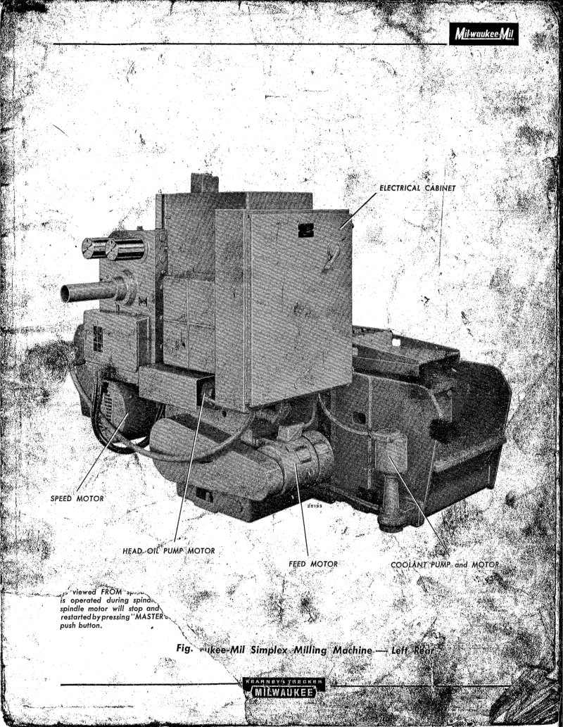
Simplex 1500 & 2000 Series Service Manual
Service manual for Milwaukee Mil Simplex milling machines, Models 1500 and 2000 Series. Contains operating controls documentation for the machine head including quill clamp nuts, adjusting dials, overarm clamp nuts, crank clutch shafts, head clamp nuts, head elevating dial, and speed range change lever. Includes electrical panel switches for disconnect switch, spindle rotation selectors (Simplex and Duplex), automatic spindle stop selector, and coolant selector with warning signal lights. Features disconnect switch positions and electrical safety interlocks.
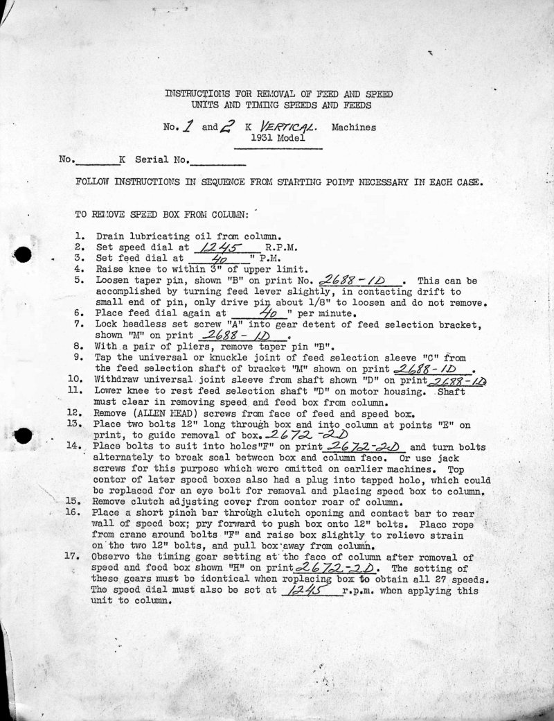
Speed & Feed Removal Instructions No. 1&2K
Service manual with detailed step-by-step instructions for removal and reassembly of speed box and feed gear train units from No. 1 and No. 2K Vertical milling machines (1931 Model). Covers drainage, dial settings, pin removal, gear train disassembly, timing gear adjustment, and complete reassembly procedures including bearing spacer placement and proper gear mesh alignment. References multiple technical drawings and print numbers.
Spindle Probe KT-Gemini Control Manual
Part programming, operating and maintenance manual for Spindle Probe with KT-Gemini control. Publication PUB 778D. Includes safety guidelines document PUB-578 from Kearney & Trecker Corporation emphasizing that safety is everybody's responsibility. Table of Contents: - The employer is responsible for selecting competent and qualified employees - Manuals are provided with each machine tool - Guards and shields are to be in place at all times - Operators must be forbidden from changing workpieces or performing other work close to a revolving cutter - When contaminants are released to the atmosphere as a result of machining, an exhaust system is recommended - All employees should be aware of first aid facilities - Employees should be encouraged to report any hazardous condition on the machine tool or in the immediate area - Air hoses must be available for use around the machine tool - Levels of illumination in the immediate area of the machine tool should comply with National Standards - Fire prevention must be practiced and fire protection available - Protective footwear safety shoes afford good protection against rolling objects - Eye protection devices must be carefully selected, fitted and used - The employer must insist that employees study this safety information and practice safety - Users must have available adequate lifting facilities capable of lifting within safe load limits - Every floor opening resulting from the machine tool installed in pits or below floor level should be covered with a material of proper strength - When machines are installed above floor level and a platform is built around the machine tool, the platform must be constructed of materials of proper strength - Management personnel have the responsibility to alert operating personnel of any unsafe practice they may observe
TF Series 320-430 Replacement Parts Manual
Replacement parts manual for Kearney & Trecker Milwaukee milling machines, models 320 TF-17, 330 TF-17, 420 TF-17, and 430 TF-17. Includes instructions for identifying and ordering replacement parts with exploded assembly views and parts lists. Contains numbered component illustrations and service contact information for the Milwaukee Service Department. Table of Contents: - Horizontal Column, Spindle Assembly - Speed Gear Box - Horizontal Column, Starting Lever and Motor Mount - Rear Controls - Knee (Feed and Rapid Traverse Drive) - Knee (Elevating) - Knee (Miscellaneous Parts) - Coolant Supply System Style "B" Arbor Support and Arm Brace - Intermediate Style Arbor Support and Style "A" Arbor Support - Model "K" Universal Spiral Dividing Head - Conventional Lead Attachment, Tail Stock and Steady Rest - Low Lead Attachment - Universal Saddle and Swivel Block - Feed Distribution Box
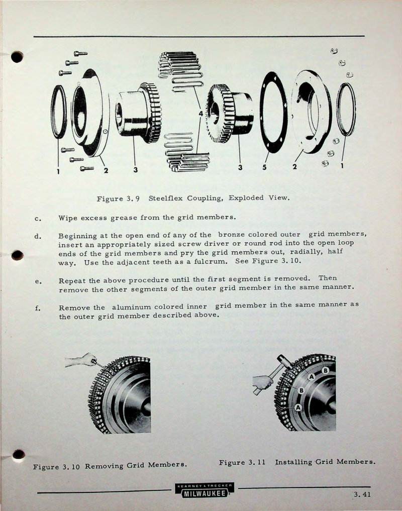
TGM 3 Model III Mill Service Manual Part 2
Part 2 of service manual for Kearney and Trecker TGM 3 Model III milling machine. Contains detailed assembly and maintenance instructions for Steelflex coupling components, including exploded views of coupling parts, grid member removal and installation procedures, reassembly with lubrication specifications using BRB #1 grease, and filter description and maintenance for the Rosaen tell-tale type filter with replaceable wire mesh cartridge in the recirculating pump pressure line.
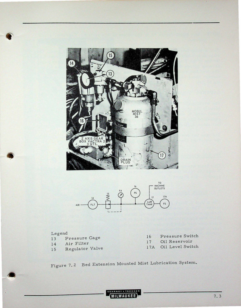
TGM 3-66 3-Axis Mill Lubrication Manual
Part 4 of the manual covers lubrication systems for the TGM 3-66 3-axis Model III milling machine. Includes detailed information on the bed extension mounted mist lubrication system with Mobil Mist 36 oil, 360,000 position table flood lubrication system with integral pump, and splash lubrication system for X and Z drive gear boxes. Contains technical diagrams, component identification, pressure specifications (65 psi maximum feed pressure, 250 psi pump relief valve setting, 5 psi pressure switch setting), and operational procedures with sight gage oil level guidelines.
TGM 3.3-66 Mill - Hydraulic System Service Manual
Part 5 of the service manual covering the hydraulic system of the TGM 3.3-66 3-axis Model III milling machine. Contains detailed disassembly, inspection, and maintenance procedures for solenoid directional control valves, the Hartmann HT-22 tool magazine drive motor with specifications (2.2 cu. in. displacement, 35 in. lb. torque per 100 psi, maximum 1500 rpm), and miscellaneous hydraulic valves including Vickers reducing valve, Double A flow control valve, and Double A pressure reducing valve. Includes cautions against using pipe wrenches on sleeve assemblies and emphasis on filter maintenance due to tight tolerances.
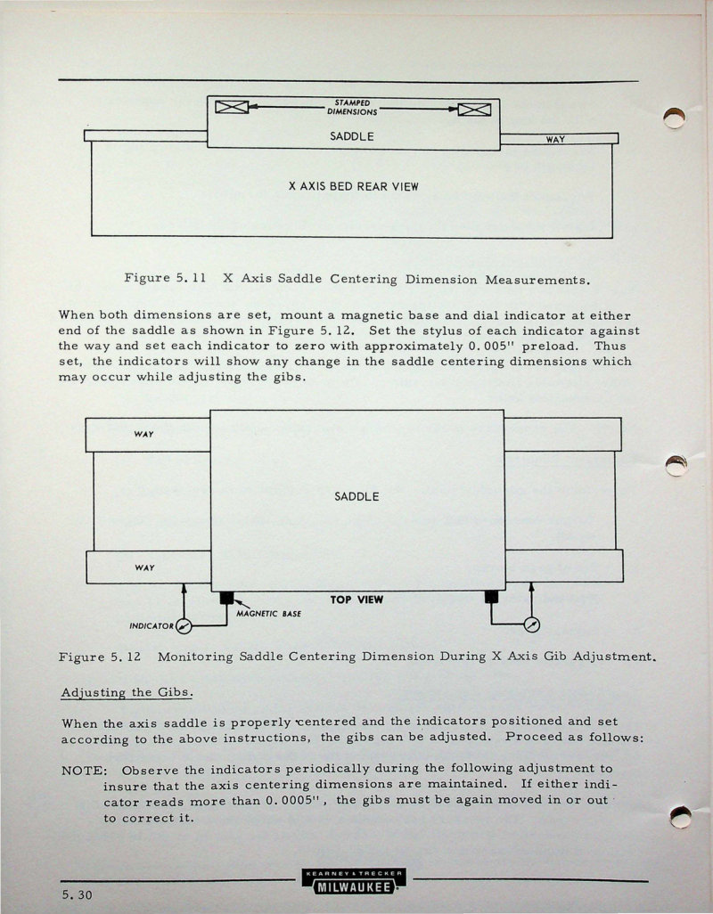
TGM 3.3-66 Mill Service Manual - Part 3
Part 3 of the service manual for the Milwaukee TGM 3.3-66 three-axis Model III milling machine. Contains detailed procedures for adjusting the X axis and Y axis gibs, including saddle centering dimension measurements, torque specifications, and step-by-step adjustment instructions with equipment requirements such as torque wrenches, dial indicators, and magnetic bases.
TRI-D Milling Head K-482 Operator's Manual
Operator's manual and replacement parts list for the Kearney & Trecker TRI-D Milling Head model K-482. Contains installation and operating instructions, pre-operational adjustments (pages 7-10), and parts list. Emphasizes the importance of performing four pre-operational adjustments each time the attachment is installed on the milling machine, and notes that any errors in machine movements will reflect in the quality of results.
VB-2, VB-4, HB-4 KT/Setup Operating Guide
KT/Setup Operating Guide for Milwaukee VB-2, VB-4, and HB-4 milling centers and machining centers with KT-GEMINI-E control (PUB 814). Document covers startup procedures, standard grid procedure, manual axis jog procedure, and coordinate system orientation for both vertical and horizontal machines. Includes checklists and operational instructions for the control system.
VB-4 Milling Centers Installation Manual
Installation manual (PUB 808B) for Milwaukee VB-4 milling centers or machining centers equipped with KT-Gemini-E control system. Published by Kearney & Trecker Corporation, Milwaukee, Wisconsin. Document also includes safety guidelines (PUB-578, First Edition May 1974) emphasizing that safety is everybody's business when operating metal cutting machine tools. Table of Contents: - The employer is responsible for selecting competent and qualified employees - Manuals are provided with each machine tool - Guards and shields are to be in place at all times - Operators must be forbidden from changing workpieces or performing other work close to a revolving cutter - When contaminants are released to the atmosphere as a result of machining, an exhaust system is recommended - All employees should be aware of first aid facilities and be encouraged to use same - Employees should be encouraged to report to their supervisors any hazardous condition on the machine tool or in the immediate area - Air hoses — it is recommended that air hoses not be available for use around the machine tool - Levels of illumination in the immediate area of the machine tool should comply with National Standards - Fire prevention must be practiced and fire protection available to prevent loss of life, personal injury and to protect property - Protective footwear — safety shoes afford good protection against rolling objects, dropping heavy objects, accidentally kicking sharp edged materials - Eye protection — eye protection devices must be considered as optical instruments and they should be carefully selected, fitted and used - The employer must insist that his employees study this safety information and practice safety - Users must have available adequate lifting facilities capable of lifting within the safe load limits; also appropriate slings and hitches - Every floor opening resulting from the machine tool installed in pits or below floor level should be covered with a material of proper strength with non-slip features - When machines are installed above floor level and a platform is built around the machine tool, the platform must be constructed of materials of proper strength with non-slip features of the walking surfaces - Management personnel have the responsibility to alert operating personnel of any unsafe practice they may observe
VB-4 with KT-Gemini-E Operating Manual
Part programming and operating manual supplement (PUB 820A) for the Milwaukee VB-4 vertical boring mill equipped with the KT-Gemini-E machine control system. Includes safety guidelines (PUB-578) emphasizing safety procedures for all occupation skill groups involved in machine operation, supervision and maintenance. Table of Contents: - Employer responsibility for selecting and training qualified employees - Manuals provided with machine tools must be available to personnel - Guards and shields must be in place at all times - Operators forbidden from changing workpieces near revolving cutters - Exhaust system recommended when contaminants released to atmosphere - First aid facilities awareness and encouragement - Employees should report hazardous conditions to supervisors - Air hoses not recommended for use around machine tools - Illumination levels must comply with National Standards - Fire prevention and protection practices - Protective footwear for safety - Eye protection devices and compulsory wearing of impact-resistant spectacles - Employer must insist employees study and practice safety - Adequate lifting facilities with safe load limits - Floor openings from machine tools must be covered with non-slip material - Machines installed above floor level require proper platform construction with non-slip features and railings - Management responsibility to alert personnel of unsafe practices