CINCINNATI - Service Manuals
239 manuals available for download
Discover comprehensive technical documentation for CINCINNATI machine tools, a trusted name in precision machining equipment. Our collection includes detailed service manuals, repair guides, operator's manuals, and workshop resources that help you maintain, troubleshoot, and optimize your equipment. Whether you need a user manual for daily operations, a maintenance guide for preventive care, or a parts list for component replacement, our PDF downloads provide the authoritative technical information required by machinists, technicians, and shop managers. Access the documentation you need to keep your CINCINNATI machines operating at peak performance.
10H/10HC Precision Centers Service Parts
Service parts manual for Cincinnati Milacron 10H and 10HC-1000/1500-2500 precision machining centers with Acramatic CNC controls. Provides systematic part identification, alphabetical cross-reference indexing, and spindle assembly part numbers for ordering replacement components. Includes contact information for regional service offices and authorized domestic and export distributors. A practical workshop reference that enables technicians and operators to quickly locate exact replacement parts needed for maintenance and repair. Table of Contents: - SERVICE REPAIR PARTS
10H/10HC Precision Machining Centers Operator's Manual
Operator's manual for Cincinnati Milacron Models 10H and 10HC-1500/2500 precision machining centers equipped with Acramatic CNC controls. Publication No. 14-25-27 IM Issue 3. Copyright 1977. This workshop manual covers operation, safety precautions, and system setup procedures essential for running these precision machining centers. 88 pages. Table of Contents: - How To Use This Manual - This manual is arranged to provide useful information with a minimum of searching. - Page numbering follows the outline of the Table of Contents. The page number is located in the lower outside corner of each page. - For the convenience of quickly finding illustrations referred to in the text, all illustrations have the same number as the page on which they appear. For example, Figure 1.2 is the illustration on Page 2 of Section 1. - There is an index in the preface with numbered thumb spots to indicate the location of each Section. - Familiarity with the Table of Contents for each section will facilitate locating particular information easily. - We suggest that, before the machine is installed, review the Table of Contents for future quick reference and a broad understanding of the layout of the book. Then read the book through and study the instructions thoroughly. - General Safety Precautions in Section 2 should be read before machine is started.
16" Series Vertical Hydro-Tel Milling Machine Owner's Manual
Owner's manual for the Cincinnati 16" Series Vertical Hydro-Tel milling machine, Publication No. M-1432-3, dated 1967. This workshop manual covers essential operation and maintenance of the machine, serving as the primary reference for setup, daily operation, and care procedures. Valuable for anyone maintaining or restoring this classic mid-century vertical milling machine. Table of Contents: - Dimensional Drawing - Machine Specifications - Installation Instructions - Foundation - Lifting the Machine - Removing Lifting Hooks and Slide Clamps - Connecting Machine to Power Source - Leveling the Machine - Cleaning the Machine - Lubricate Machine Thoroughly - Starting the Machine for the First Time - Releasing the Spindle Carrier and Counterweight - Preliminary Run-In - Initial Pressure Adjustment - Lubrication - Ways Lubrication - Lubrication Diagrams - Lubricating Instructions and Specifications - Hydraulic Unit - General Description - Draining the Oil Tanks - Cleaning the Hydraulic Oil Filters - Checking and Adjusting Hydraulic Pressures - Cleaning the Stone Filters - Brief Machine Description - General Purpose Milling Machine - Die-Sinking Machine with Depth Control - Automatic 360° Profiling Machine - Operating Instructions - General Description - Electrical Control Panel - Functional Diagram - Table Hand Feed - Table Power Feed and Power Rapid Traverse - Changing Table Feed Rate - Hand Cross Feed - Cross-Slide Feed and Rapid Traverse - Changing the Cross-Slide Feed Rate
190 Series Press Brake Operator's Manual
Operator's manual for Cincinnati Press Brakes, 190 Series and larger models. Published by The Cincinnati Shaper Company, Cincinnati, Ohio. Contains receiving instructions, installation guidelines, lifting and moving procedures for the four main members (right-hand housing, left-hand housing, bed, and ram) of the press brake. Includes Illustration No. 1 showing proper lifting techniques using clevis or cable attachments.
2-3-4 Dial Type Milling Machines Service Manual
Service manual and parts list for Cincinnati 2, 3 and 4 dial type milling machines, Model LL series, covering machines manufactured 1955 through 1959. Published by The Cincinnati Milling Machine Co., Cincinnati, Ohio. This workshop manual provides maintenance personnel with detailed servicing methods, component replacement procedures, and ordering information for genuine repair parts. Original copyright 1957.
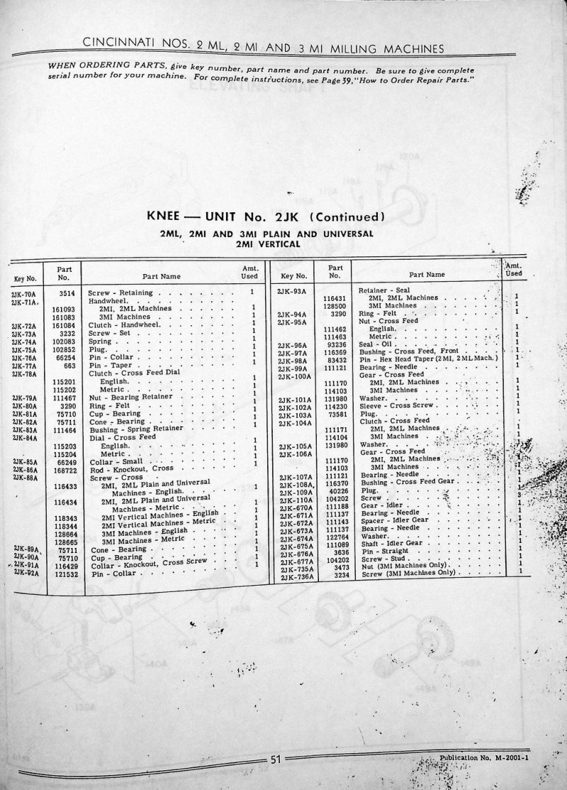
2ML, 2MI, 3MI Milling Machines Parts List
Parts list catalog for Cincinnati Nos. 2ML, 2MI and 3MI milling machines. This service manual provides detailed parts listings for the Knee Unit No. 2JK across 2ML, 2MI and 3MI models in both standard and universal configurations, including the 2MI vertical variant. Each entry includes precise part numbers and quantities required for assembly and maintenance. An exploded technical drawing of the Elevating Shaft assembly illustrates all components from 111A through 149A, enabling technicians to quickly identify and order parts for repairs or routine maintenance on these Cincinnati machines. Publication No. M-2001-1.
307-14 & 410-14 MI Milling Machines Operator Manual
Operator's instruction manual for the Cincinnati 307-14 MI and 410-14 MI plain and universal milling machines. Publication No. 2383. This workshop manual provides practical guidance on fundamental operating procedures, machine setup, and routine operation for both models. Essential reference for machine operators and maintenance personnel responsible for these industrial milling machine tools. Table of Contents: - General Specifications - Dimensional Drawings - Standard Equipment - Installation Instructions - Foundation - Facing the Machine - Bolting the Machine to the Floor - Leveling - Assembling the Table - Backlash Eliminator - Lubrication - Lubrication Diagram - Lubricating Instructions - Starting the Machine for the First Time - Functional Diagram - Operating Instructions - Starting the Machine - Changing Spindle Speeds - Changing Feed Rate - Micrometer Dials - Table Traverse Handwheel - Cross Traverse Handwheel - Vertical Traverse Handcrank - Power Feed Levers - Power Table Feed - Power Cross Feed - Power Vertical Feed - Power Rapid Traverse - Rear Controls - Setting Up the Machine - Fixtures and Cutters - Overarm, Supports, and Brace - Clamping Devices - Reversing Direction of Spindle Rotation - Feed Trip Dogs - Changing from Steel to Cast Iron Jobs
3VTC-1800 Programmers Manual
Programmers manual for the Cintimatic Model 3VTC-1800 machining center equipped with the Cincinnati Acramatic Series 5 Control. This workshop manual covers CNC programming format and tape preparation essential for operating the machine tool. Pages 2-3 provide detailed word definitions (Words 1-12) covering sequence numbering, preparatory functions, and axis coordinate specification for X, Y, and Z axes. Includes programming form reference sheets detailing data sequence layout, tape format specifications, multi-axis coordinate coding conventions, and machine control parameters needed for proper part program setup and execution. Table of Contents: - FULL RANGE FLOATING ZERO
A Treatise on Milling and Milling Machines
Comprehensive technical treatise on milling and milling machines from The Cincinnati Milling Machine Co. of Cincinnati, Ohio. This 420-page workshop manual covers foundational principles, machine operation, and practical applications of milling equipment. Spans the full scope of milling processes and machinery design as documented by one of the era's leading machine tool manufacturers. Essential reference for machinists, tool engineers, and anyone working with or maintaining milling equipment. Includes title page and front matter. Table of Contents: - The Construction and Use of Milling Machines - Chapter — Erection, Care and Adjustment of Milling Machines - Chapter — Toolroom Millers - The Dividing Head, etc - Chapter IV — Setting up the Machine - Chapter V — An Analysis of the Process of Milling - Chapter VI — Milling Machine Feeds - Chapter VII — Speeds of Milling Cutters - Chapter VIII — Stream Lubrication - Cutter and Work-Cooling System - Chapter IX — Milling Cutters - Notes on the Design and - Efficiency - Modern Cutters - Chapter X — Cutter Sharpening
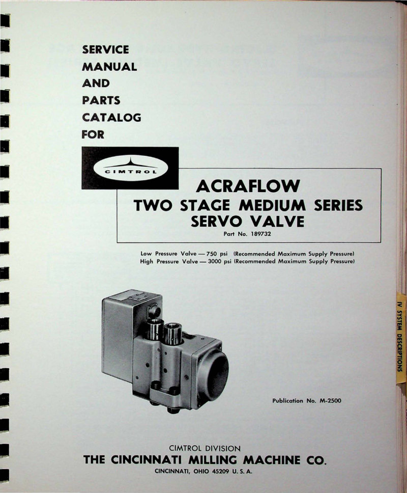
Acraflow Two Stage Medium Servo Valve Manual
Service manual and parts catalog for the CIMTROL Acraflow two-stage medium series electro-hydraulic servo valve (Part No. 189732). This workshop manual covers both the low-pressure valve rated at 750 psi and the high-pressure version at 3000 psi, with complete valve identification and construction details. Includes torque motor specifications detailing the 2300 ohm coil option (0.0067 inch deflection) and 20 ohm alternative (0.00011 inch deflection), dither system operation and adjustment, and comprehensive flow ratings spanning 5 to 50 gpm across multiple pressure drop conditions. Technical reference publication M-2500 from The Cincinnati Milling Machine Co., CIMTROL Division. An essential troubleshooting and maintenance guide for technicians working with Cincinnati servo valve systems.
Acramatic 220 Programmer's Manual
Programmer's manual for the Cincinnati Acramatic 220 control system on Single Spindle Cintimatics 200 Series machines. This workshop manual covers tape format specifications and console panel operation, including pendant station setup and control. Essential sections address Z-axis depth cam calibration and zero shift initialization—critical setup procedures for accurate tool positioning. The guide includes detailed programming examples for common machining cycles: drilling, boring, tapping, and milling operations, along with preparatory functions needed to configure your machine for production work. Publication M-2738-B2. Table of Contents: - Chapter I INTRODUCTION - Chapter II GENERAL TAPE INFORMATION - A. Format Type - B. Tab Codes - C. Code Delete - D. End of Block - E. Tape Leader - Chapter III FUNCTIONS OF INDICATORS AND MANUALLY OPERATED CONTROLS - A. Acramatic 220 Console Panel - B. Cintimatic Pendant Station - C. Setup Procedure - 1. Z-Axis Depth Cam Setting - 2. Zero Shift Setup - Chapter IV TAPE FORMAT — ACRAMATIC 220 - A. Block Diagram - B. Format Description - 1. Sequence Number Coding - 2. Preparatory Function - 3. Coordinate Information - 4. Miscellaneous Function Coding - C. Specific Programming Examples - 1. Preparatory Functions - a. Drill Cycle - b. Bore Cycle - c. Tap Cycle - d. Tapered Pipe Tapping - e. Basic Mill Cycle - f. Mill Cycle (Clamp Quill) - g. Light Mill Cycle (Automatic Quill Retraction) - h. Cancel Cycle - i. Dwell Cycle
Acramatic 220 Programmer's Manual
Programmer's manual for the Cincinnati Acramatic 220 Single Spindle control system within the Cintimatics 200 Series product line. This workshop reference covers the essentials of preparing and entering control tape: tape format standards, tab codes, code deletion, end-of-block markers, and tape leader setup. The manual explains the operation and function of all panel indicators and manually operated controls found on the Acramatic 220 console, the Cintimatic pendant station, and the setup procedures required for Z-axis depth cam configuration and zero shift alignment. A complete tape format specification section includes block diagrams and format descriptions detailing sequence number coding, preparatory functions, coordinate data entry, and miscellaneous function codes. Practical programming examples walk through drill cycles, bore cycles, tap cycles, tapered pipe tapping operations, basic milling sequences, milling with clamped quill, light milling with automatic quill retraction, cycle cancellation, and dwell timing. Essential reference for anyone setting up, programming, or maintaining Cincinnati Acramatic 220 equipment.
Acramatic Model 220 Positioning Control Manual
Operation and maintenance manual for the Cincinnati Acramatic Model 220 positioning control system. Publication No. M-2738-A1, Part No. 3 501 0001A. Produced by CIMTROL Division of The Cincinnati Milling Machine Company. This comprehensive workshop manual covers operational procedures, maintenance routines, and troubleshooting guidance for technicians servicing this industrial positioning control unit. Includes detailed technical reference material for setup, calibration, and everyday operation of the Acramatic 220 system. Essential documentation for machine shops and maintenance departments responsible for keeping this control system in peak working condition. Table of Contents: - I don't see a table of contents on this page. This page contains instructions titled "HOW TO USE THIS MANUAL" that explains the manual's organization and numbering system, but it does not include actual table of contents entries.
Acramatic Thousand Series Programmers Manual
Programmers manual for the Cincinnati Acramatic Thousand Series Universal Numerical Control system. This workshop manual describes the use and operation of the CINAP computer routine, the core programming interface for machine control. Covers CINAP routine input/output protocols, programming sample parts, and the SMART routine for scaling, mirror imaging, and translation transformations. Includes detailed sections on points, lines, circles, feed rates, spindle control, cutter compensation, and a comprehensive error codes reference for troubleshooting. Essential reference for CNC programmers and operators working with Acramatic Thousand Series equipment. Table of Contents: - INTRODUCTION - General - CINAP Forms - CINAP ROUTINE INPUT - Points, Lines and Circles - Points - Lines - Circles - Outside Corner - Point to Point Movement - Stop Points - Circular Definition - Symbol Allocation Table - Special Functions - Feed Rate - G Codes - Cutter Compensation "CTCOM" - Spindle-Coolant - Cutter Offset - End of Program - Part Number - Axis Exchange - Machine Number - Order and Size of Input - Other - Size - Subdividing the Program - Part Programmer's Guide - Error Codes - CINAP ROUTINE OUTPUT - Output Formats - Addresses - Preparatory Functions - Miscellaneous Functions - Coded Speeds - Decimal Position - Flag - Total Time — Length of Tape - PROGRAMMING A SAMPLE PART - Part Program - SMART ROUTINE- (Scaling, Mirror Image, And Routine, Translation) - Introduction - Scaling - Mirror Image - Rotation - Translation - Error Codes
BTC Collet Chuck Technical Data - Erickson
Technical data and precision drawings for Erickson BTC Collet Chuck models 100 and 150, both fitted with Cincinnati #45 Taper mounting. Includes complete dimensional specifications for Erickson Tool No. BM1-C-104788 (No. 100 BTC Collet Chuck) and Erickson Tool No. BM1-C-104789 (No. 150 BTC Collet Chuck). Detailed technical drawings cover spindle shank profiles, collet capacity ranges (3/32 to 1 inch for model 100; 1 to 1.5 inches for model 150), hex key dimensions, and collet holding specifications. Essential reference material for setup, tooling selection, and maintenance of Cincinnati machine tool spindle installations using BTC collet systems.
Bulletin 806 Rotary Pilot Switches Instructions
Instructions for Cincinnati Bulletin 806 Style B rotary pilot switches manufactured by Allen-Bradley. This workshop manual covers the practical conversion of surface-mounted drum switches to panel or cavity mounting configurations, with complete dimensional specifications and detailed technical drawings. The guide walks through procedures for converting switches from maintained contact operation to self-centering (spring return) modes, applicable to both single-throw and double-throw switch designs. Includes illustrated mounting configurations for panel, surface, and cavity installations.
Cincinnati 1-12 & 1-18 Milling Machines Service Manual
Service manual and parts catalog for Cincinnati Nos. 1-12 and 1-18 Plain Automatic Milling Machines, Model EA. Covers essential service adjustments including driving belts, drive clutch engagement, feed and rapid-traverse safety clutches, gibs, lead screw bearings, and spindle bearing setup. Details automatic table movement sequences, ball and roller bearing specifications, functional schematics, and lubrication point locations throughout the machine. Provides knee-hydraulic and oil line routing diagrams, plus step-by-step dismantling procedures for the column assembly, drive bracket, and knee components. Includes a directory of Cincinnati field offices and authorized service representatives for technical support. Publication No. M-1190-1. Identification No. 2F-OL. This workshop manual is essential for technicians performing maintenance, troubleshooting, or component replacement on these classic Cincinnati milling machines.
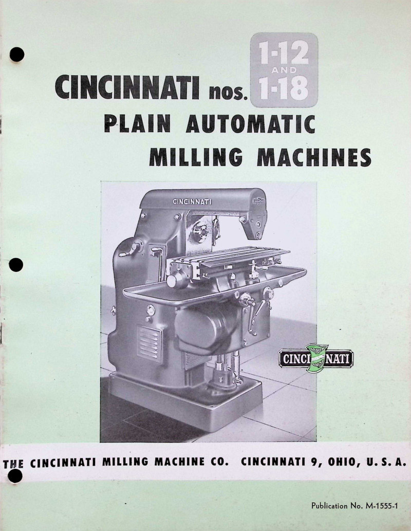
Cincinnati 1-12 & 1-18 Milling Machines Service Manual
Service manual for Cincinnati models 1-12 and 1-18 plain automatic milling machines. This workshop manual documents essential maintenance, operation and repair procedures for these classic industrial milling systems. Coverage includes detailed treatment of the machines' principal design features: sixteen spindle speed options ranging from 50 to 1600 rpm, sixteen independent two-way table feed rates, fully automatic table traverse cycles with coordinated motion control, power-driven rapid traverse capability, responsive finger-tip control interface, reinforced knee assembly with extended table and column bearing surfaces, manual table control lever operation, the ability to change spindle speeds and feeds without requiring wrenches, automatic backlash compensation mechanism, automatic spindle shutdown function, robust four-bearing spindle mounting system, automatic lubrication delivery, handwheel-based adjustment capability, integrated coolant and chip deflection guards, motor installation within the column structure, rectangular overarm and arbor support geometry, and hand-operated adjustment cranks for fine positioning. The manual provides full mechanical illustrations depicting the machines in complete configuration, operating control layouts and procedures, comprehensive general specifications, detailed equipment descriptions, dimensional engineering drawings, and complete electrical specifications for installation and troubleshooting.
Cincinnati 1-12 & 1-18 Service Manual
Service manual and parts list for Cincinnati Nos. 1-12 and 1-18 Plain Automatic Milling Machines, Model EA. This workshop manual covers essential adjustments including driving belts, clutches, gibs, spindle bearings, and lead screw bearings. Dismantling instructions detail the column, drive bracket, and knee assemblies; automatic table movements are explained with functional diagrams and oiling station locations throughout. Indexed with detailed page references for quick navigation. Originally published 1942. Applicable to machines bearing serial prefix 2F. Table of Contents: - ADJUSTMENTS - To Adjust Driving Belts - To Adjust Driving Clutch - To Adjust Feed Safety Clutch - To Adjust Gibs - To Adjust Lead Screw Bearings - To Adjust Rapid Traverse Safety Clutch - To Adjust Spindle Bearings - AUTOMATIC TABLE MOVEMENTS - DIAGRAMS AND ILLUSTRATIONS - Dimensional Drawing - Functional Diagrams - Functional Diagrams and Oiling Stations - Knee-Hydraulic and Lubricating Oil Tubing - DISMANTLING INSTRUCTIONS - For Column - Remove and Dismantle Quill Adjusting Bracket - Remove and Dismantle Spindle - Remove Spindle Sleeve and Gears - Remove and Dismantle Feed Drive Shaft - For Drive Bracket - Remove Drive Bracket, Starting Lever Shift and Its Detent Plunger - Dismantle Back Gear Shaf - Remove Feed Drive Gear - Dismantle Reverse Shaft - Dismantle Clutch Shaft - For Knee - Remove Table and Lead Screw - Remove and Dismantle Lead Screw Bearing, Nut and Retainer - Remove Knee and Vertical Spline Shaft Bearing - Remove and Dismantle Spindle Stop Bracket - Remove and Dismantle Shifter Bracket - Remove and Dismantle 2nd Feed Shaft, Sleeve and Shaft Gears - Remove 3rd Feed Shaft and Table Lead Screw Drive - Remove 1st Feed Shaft - Remove and Dismantle Feed Trip Plunger
Cincinnati 1-12/1-18 Service Manual & Parts
Service manual and parts list for Cincinnati 1-12 and 1-18 Plain Automatic Milling Machines, Model EA. This workshop manual covers essential maintenance and repair procedures for these classic Cincinnati machines, including detailed adjustment guidance, automatic table movement operations, and step-by-step dismantling instructions for the column, drive bracket, and knee assembly. You'll find comprehensive ball and roller bearing specifications, functional diagrams illustrating the machine's systems, lubrication point maps showing all oiling stations, and hydraulic tubing layouts for the knee circuit. The manual includes complete dimensional drawings and detailed parts breakdown to help you source or replace components with confidence. Applicable to serial numbers beginning with prefix 2F. Original documentation from The Cincinnati Milling Machine Co., Cincinnati 9, Ohio, copyright 1942. An authoritative reference for owners and technicians maintaining these rugged production machines. Table of Contents: - SERVICE MANUAL ADJUSTMENTS - To Adjust Driving Belts - To Adjust Driving Clutch - To Adjust Dynamoise Overarm - To Adjust Feed Safety Clutch - To Adjust Gibs - To Adjust Lead Screw Bearings - To Adjust Rapid Traverse Safety Clutch - To Adjust Spindle Bearings - AUTOMATIC TABLE MOVEMENTS - BALL AND ROLLER BEARING DATA - DIAGRAMS AND ILLUSTRATIONS - Dimensional Drawing - Functional Diagrams - Functional Diagrams and Oiling Stations - Knee-Hydraulic and Lubricating Oil Tubing - DISMANTLING INSTRUCTIONS - For Column - Remove and Dismantle Quill Adjusting Bracket - Remove and Dismantle Spindle - Remove Spindle Sleeve and Gears - Remove and Dismantle Feed Drive Shaft - For Drive Bracket - Remove Drive Bracket, Starting Lever Shift and Its Detent Plunger - Dismantle Back Gear Shaft - Remove Feed Drive Gear - Dismantle Reverse Shaft - Dismantle Clutch Shaft - For Knee - Remove Table and Lead Screw - Remove and Dismantle Lead Screw Bearing, Nut and Retainer - Remove Knee and Vertical Spline Shaft Bearing - Remove and Dismantle Spindle Stop Bracket - Remove and Dismantle Shifter Bracket - Remove and Dismantle 2nd Feed Shaft, Sleeve and Shaft Gears - Remove 3rd Feed Shaft and Table Lead Screw Driver - Remove 1st Feed Shaft - Remove and Dismantle Feed Trip Plunger
Cincinnati 1-12/1-18 Service Manual and Parts
Service manual and parts list for the Cincinnati No. 1-12 and No. 1-18 Plain Automatic Milling Machines, Model EA. Originally published by The Cincinnati Milling Machine Company, Cincinnati, Ohio in 1942. This workshop manual provides detailed service procedures and comprehensive repair parts information essential for maintaining and troubleshooting these horizontal milling machines. A valuable reference for operators, maintenance technicians, and machine shops working with Cincinnati plain automatic mills from this era. Table of Contents: - ADJUSTMENTS - To Adjust Driving Belts - To Adjust Driving Clutch - To Adjust Feed Safety Clutch - To Adjust Gibs - To Adjust Lead Screw Bearings - To Adjust Rapid Traverse Safety Clutch - To Adjust Spindle Bearings - AUTOMATIC TABLE MOVEMENTS - DIAGRAMS AND ILLUSTRATIONS - Dimensional Drawing - Functional Diagrams - Functional Diagrams and Oiling Stations - Knee-Hydraulic and Lubricating Oil Tubing - DISMANTLING INSTRUCTIONS - For Column - Remove and Dismantle Quill Adjusting Bracket - Remove and Dismantle Spindle - Remove Spindle Sleeve and Gears - Remove and Dismantle Feed Drive Shaft - For Drive Bracket - Remove Drive Bracket, Starting Lever Shift and Its Detent Plunger - Dismantle Back Gear Shaft - Remove Feed Drive Gear - Dismantle Reverse Shaft - Dismantle Clutch Shaft - For Knee - Remove Table and Lead Screw - Remove and Dismantle Lead Screw Bearing, Nut and Retainer - Remove Knee and Vertical Spline Shaft Bearing - Remove and Dismantle Spindle Stop Bracket - Remove and Dismantle Shifter Bracket - Remove and Dismantle 2nd Feed Shaft, Sleeve and Shaft Gears - Remove 3rd Feed Shaft and Table Lead Screw Drive - Remove 1st Feed Shaft - Remove and Dismantle Feed Trip Plunger
Cincinnati 1-2-3-4 Dial Type Milling Service Manual
Service manual and repair parts catalog for Cincinnati Nos. 1-2-3-4 dial type milling machines, covering both medium speed and high speed models. This workshop manual provides comprehensive lubrication charts and instructions essential for proper machine maintenance, along with detailed installation procedures and adjustment techniques for gibs and clutches. The guide includes step-by-step disassembly and reassembly instructions for major components such as the leadscrew, table, universal housing, spindles, feed mechanisms, and gear assemblies. Published by The Cincinnati Milling Machine Company, Cincinnati, Ohio. Table of Contents: - Lubrication Chart for All Machines - Lubrication Instructions and Specifications - Nomenclature Chart - Installation Instructions - Adjusting the Gibs and Main Driving Clutch - Adjusting the Rapid Traverse Clutch - Removing Leadscrew - Removing Table - Removing Universal Housing - Removing Cross Screw - Removing Cross Screw Nut Bracket - Removing Saddle - Removing Spline Shaft Bracket - Removing Vertical Screw - Removing Change Gear Bracket - Removing Lubricant Pump in Knee - Removing the Knee - Removing Coolant Pump - Removing Pulley Bracket - Removing Feed Box - Removing Gear Shifter Bracket - Removing Hand Feed Worm Box - Removing Power Feed Worm Box - Removing Vertical Spindle - Removing Vertical Head - Removing Horizontal Spindle - Adjustment of Spindle Bearings - Illustration of Front of Column - Removing the Back Gear Shaft - Removing Other Drive Shafts - Removing More Than One Unit - Removing the Overarm - Removing Rear Control Bracket - Setting the Oil Pressure of Pump in Column - Removing the Pressure Pump in Column - Lubrication of Column
Cincinnati 100 Series Milling Machine Service Manual
Service manual and comprehensive parts list for the Cincinnati 100 Series Powermatic milling machine, Model DK — covering both standard and hydraulic rise-and-fall configurations. Published by The Cincinnati Milling Machine Co., Cincinnati, Ohio. This workshop manual provides detailed technical guidance for maintenance, repair, and parts identification. Identification No. 7F-DD, Publication No. M-2684. Copyright 1968. Table of Contents: - FUNCTIONAL DIAGRAMS - DIMENSIONAL DRAWINGS - INSTALLATION - Location - Lifting - Bolting the Machine to the Foundation - Leveling - Cleaning and Initial Lubrication - LUBRICATION - General - Spindle Carrier Way Lubrication - Sible Way Lubrication - LUBRICATION DIAGRAM - LUBRICATION INSTRUCTIONS AND SPECIFICATIONS - ADJUSTMENTS - To Adjust Gibs - To Adjust Arbor Support Bushings - To Adjust Drive Belts - To Adjust Spindle Bearings - To Adjust Main Hydraulic Pressure - To Check Hydraulic Rise and Fall Pressure - To Adjust Cam Roller Hydraulic Pressure - To Adjust Table Lead Screw Nut Bearings - To Adjust "Dynapoise" Overarm - MAINTENANCE - Maintenance and Operating Hints - Trouble Shooting Chart - DISMANTLING - General - To Disassemble Vertical Lift Screw (Plain Machines) - To Disassemble Vertical Lift Screw (Rise and Fall Machines) - To Remove Spindle Carrier - To Remove "C" Shaft
Cincinnati 100 Series Powermatic DK Service Manual
Service manual and comprehensive parts list for the Cincinnati 100 Series Powermatic DK milling machine, covering both standard and hydraulic rise-and-fall configurations. Published by The Cincinnati Milling Machine Co., Cincinnati, Ohio, copyright 1970. This workshop manual includes functional block diagrams, dimensional engineering drawings, step-by-step installation procedures, detailed lubrication schedules, adjustment techniques, preventive maintenance routines, systematic troubleshooting guides, and complete disassembly procedures. Applies to machines with serial numbers beginning with 7F. An essential technical reference for technicians performing repairs, rebuilds, and routine service on this classic industrial milling machine. Table of Contents: - FUNCTIONAL DIAGRAMS - DIMENSIONAL DRAWINGS - INSTALLATION - Location - Lifting - Bolting the Machine to the Foundation - Leveling - Cleaning and Initial Lubrication - LUBRICATION - General - Spindle Carrier Way Lubrication - Table Way Lubrication - LUBRICATION DIAGRAM - LUBRICATION INSTRUCTIONS AND SPECIFICATIONS - ADJUSTMENTS - To Adjust Gibs - To Adjust Arbor Support Bushings - To Adjust Drive Belts - To Adjust Spindle Bearings - To Adjust Main Hydraulic Pressure - To Check Hydraulic Rise and Fall Pressure - To Adjust Cam Roller Hydraulic Pressure - To Adjust Table Lead Screw Nut Bearings - To Adjust "Dynapoise" Overarm - MAINTENANCE - Maintenance and Operating Hints - Trouble Shooting Chart - Valve Lapping Procedure - DISMANTLING - General - To Disassemble Vertical Lift Screw (Plain Machines) - To Disassemble Vertical Lift Screw (Rise and Fall Machines) - To Remove Spindle Carrier - To Remove "C" Shaft
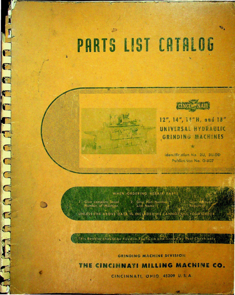
Cincinnati 12-18 inch Universal Hydraulic Parts List
Parts list and technical reference for Cincinnati 12, 14, 14H, and 18 inch Universal Hydraulic Grinding Machines, Model DE 2. This comprehensive parts catalog provides everything needed to identify, source, and order replacement components for these precision machines. The manual includes a detailed index, identification diagrams with part locations, dimensional drawings for reference, complete lubrication diagram and maintenance chart, installation instructions for components, filter specifications and notes, and adjustment procedures. A comprehensive numbered parts listing with cross-reference index makes locating the correct part number quick and reliable. Publication No. G-897, Identification No. 2U, 3U-DD. Applies to machines with serial numbers beginning with 2U or 3U. Table of Contents: - ADJUSTMENTS - To adjust Grinding Wheel Spindle Bearings - To adjust Grinding Wheel Spindle Thrust Bearing - To adjust Grinding Wheel Spindle V-Belt Drive - To adjust Headstock Motor Drive V-Belts - To adjust Hydraulic Oil Pressure - To adjust Internal Grinding Attachment Belt Drive - To adjust Volume of Oil to Table Ways - To adjust Volume of Oil to Wheelhead Ways - CONVERSION CHART - DIMENSIONAL DRAWINGS - FILTER NOTES - IDENTIFICATION DIAGRAMS - INSTALLATION INSTRUCTIONS - LUBRICATION DIAGRAM and CHART - LUBRICATION OF THE WAYS - PARTS LIST CATALOG - How to Order Repair Parts - Key Number Index - Parts Listing - RECOMMENDED LUBRICANTS
Cincinnati 12" Hydraulic Universal Grinder Operator's Manual
Operator's manual for the Cincinnati 12" Hydraulic Universal Grinder, a mid-century precision grinding machine from Cincinnati Grinders Incorporated. This instruction book covers proper setup, operation, and maintenance of the hydraulic grinding system, with introductory guidance on machine fundamentals. Original publication 1942, Cincinnati, Ohio. A valuable reference for restoring, maintaining, or operating this industrial grinding equipment.
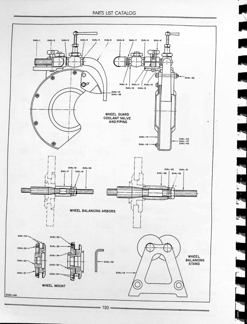
Cincinnati 12"-18" Hydraulic Grinding Parts List
Parts list catalog for Cincinnati 12", 14", 16", and 18" hydraulic universal grinding machines. Includes exploded views and part numbers for the wheel guard, coolant valve and piping system, wheel balancing arbors, wheel mount assembly, and balancing stand. Each component breakdown provides detailed part reference numbers needed to identify and order genuine Cincinnati service and replacement parts. Use this workshop reference when planning maintenance, repairs, or machine assembly work.
Cincinnati 130 Series X 10 Operator's Manual
Operator's manual and safety guide for the Cincinnati A.M.R. Industries 130 Series X 10' mechanical press brake (Serial 21523). This workshop manual covers essential safety protocols for press brake operation, including proper machine setup, control functions, and safe handling practices. Provides detailed operating instructions for running the machine safely and effectively in production environments. Table of Contents: - UNLOADING - LIFTING - FOUNDATION
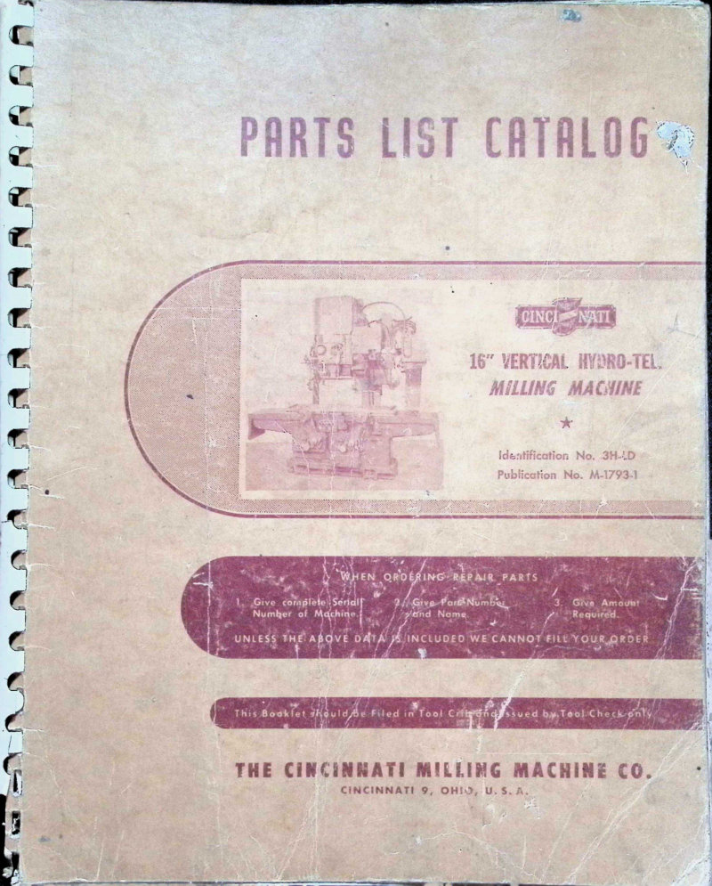
Cincinnati 16" Hydro-Tel Milling Machine Parts List
Comprehensive parts list for the Cincinnati 16" Vertical Hydro-Tel Milling Machine, Model OE (Identification No. 3H-LD). This official parts catalog, Publication No. M-1793-1, provides detailed part numbers and component identification essential for ordering replacement parts and servicing your machine. Originally published by The Cincinnati Milling Machine Co. in Cincinnati, Ohio in 1955, this catalog remains the authoritative reference for locating correct components. The manual acknowledges that design refinements across production runs may result in minor variations in component appearance, helping you identify equivalent parts. Whether you're performing routine maintenance or undertaking repairs, this parts list ensures you order the exact replacements needed to keep your Hydro-Tel mill running smoothly.
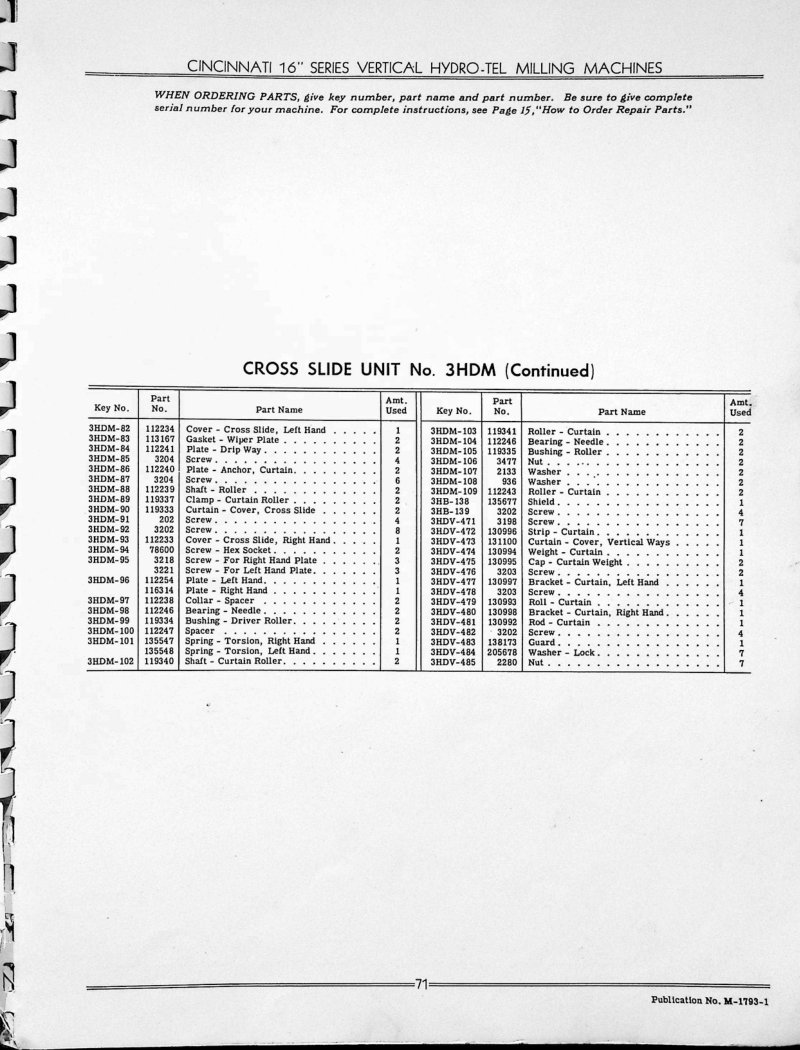
Cincinnati 16" Vertical Hydro-Tel Parts List
Comprehensive parts list and catalog for Cincinnati 16 Series Vertical Hydro-Tel milling machines. This workshop manual covers the Cross Slide Unit No. 3HDM (continued and concluded sections) and the Motor Drive Unit No. 3HN, providing machinists and maintenance technicians with detailed part identification for servicing and rebuild work. Each component is cataloged with key numbers, part names, manufacturer part numbers, and quantity information, essential for ordering replacements and understanding machine assembly. Mechanical components covered include covers, plates, fasteners, bearings, washers, clamps, curtains, rollers, shields, brackets, and complete motor drive subassemblies. Illustrated diagrams throughout show dog strips, clamp mechanisms, and motor drive assembly layouts with numbered cross-references for precise component location.
Cincinnati 1M Miller Parts List Service Manual
Parts list and service repair book for the Cincinnati 1M milling machine with 3-way power rapid traverse. Includes nomenclature chart, dismantling instructions for all major components, parts diagrams with exploded views, and ordering information. Document covers Plain, Universal, and Vertical machine types.
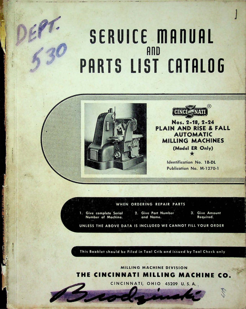
Cincinnati 2-18, 2-24 Milling Machine Service Manual
Service manual and parts list catalog for Cincinnati Nos. 2-18 and 2-24 Plain and Rise & Fall Automatic Milling Machines, Model ER only. Contains repair procedures and parts information. Copyright 1943. Identification No. 1B-DL, Publication No. M-1270-1.
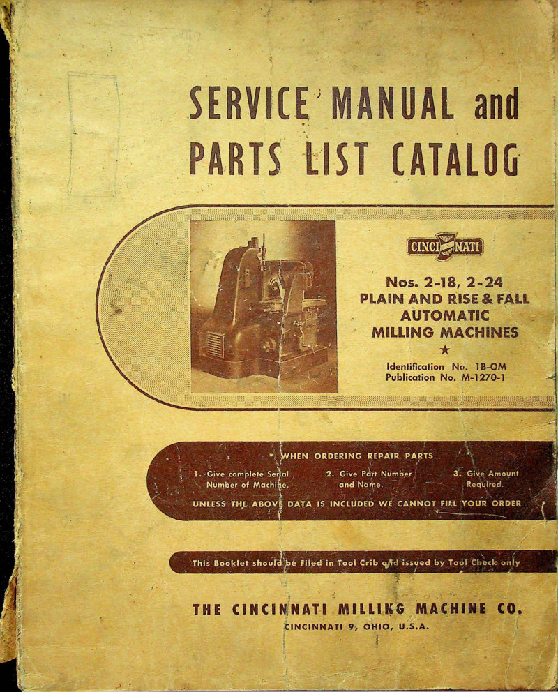
Cincinnati 2-18, 2-24 Service Manual & Parts List
Service manual and parts list for Cincinnati 2-18 and 2-24 plain and rise-and-fall automatic milling machines, model ER. Published by The Cincinnati Milling Machine Co., Cincinnati 9, Ohio. This workshop manual covers adjustment procedures, automatic cycle operation, automatic table movements, cycle operation charts, dimensional drawings, spindle carrier dismantling instructions, and oil tubing schematic layouts. Applies to machines with serial numbers beginning 1B. Includes detailed troubleshooting and maintenance guidance for keeping these industrial milling machines in proper operating condition. Table of Contents: - ADJUSTMENTS - AUTOMATIC CYCLES—TYPICAL (Plain Machines Only) - AUTOMATIC TABLE MOVEMENTS (Plain Machines Only) - CHARTS OF CYCLE OPERATIONS (Rise & Fall Machines Only) - DIAGRAMS AND ILLUSTRATIONS - Plain Automatic Machines Only - Dimensional Drawing - Front Left View - Front Right View - Right Rear View - Schematic Layout of Oil Tubing - Automatic Rise & Fall Machines Only - Dimensional Drawing - Front Left View - Front Right View - Right Rear View - Looking Into Table Bed—Feed Box Removed - Schematic Layout of Oil Tubing - DISMANTLING INSTRUCTIONS - For Spindle Carrier - Remove and Dismantle Quill Bracket, Quill and Spindle - Spindle Carrier - Rise and Fall Unit (Rise & Fall Machines Only)
Cincinnati 2-18/2-24 Milling Machines Owner's Manual
Owner's manual for the Cincinnati No. 2-18 and 2-24 Automatic Rise and Fall Milling Machines, published in 1941 by The Cincinnati Milling Machine Co. This workshop manual provides comprehensive operating instructions and maintenance guidance for keeping these precision machines accurate and performing reliably. The manual covers proper setup, adjustment procedures, and best practices to help operators achieve consistent results and extend machine longevity. Anyone restoring, operating, or maintaining a Cincinnati 2-18 or 2-24 will find the practical technical information needed in this classic milling machine service reference.
Cincinnati 2-3-4 Dial Type Milling Machines Service Manual
Comprehensive service manual for Cincinnati 2-3-4 dial type milling machines, model LD. This workshop manual covers essential adjustments, dismantling procedures, and maintenance requirements for reliable operation. Detailed lubrication diagrams guide proper oil distribution throughout the machine, while dimensional drawings and parts assembly illustrations ensure accurate restoration. Coverage includes arbor support bushings, backlash eliminator adjustment, hydraulic oil pressure settings for column and knee systems, feed screw and spindle bearing service, main drive clutch and V-belt maintenance, vertical screw brake operation, and elevation mechanism function. A complete parts list with component specifications and assembly details supports technicians performing repairs, overhauls, and routine servicing on these precision milling machines. Table of Contents: - ADJUSTMENTS - To Adjust Arbor Support Bushings - To Adjust Backlash Eliminator - To Adjust Column and Knee Hydraulic Oil Pressure - To Adjust Cross Feed Screw Bearing - To Adjust Dynapoise Overarm - To Adjust Front Elevating Screw Bearing - To Adjust Gibs - To Adjust Main Drive Clutch - To Adjust Main Drive V-Belts - To Adjust Relationship Between Feed Trip Plunger and Control Plunger - To Adjust Spindle Bearings - To Adjust Table Lead Screw Bearings - To Adjust Vertical Screw Brake - CONVERSION CHART (Inches to Millimeters) - DIAGRAMS AND ILLUSTRATIONS - Dimensional Drawings - Functional Illustrations - Lubrication Diagram - DISMANTLING INSTRUCTIONS - To Dismantle Knee - Removal and General Information - Bracket -Under- Saddle - Cam Reversing Mechanism - Control - Levers - and shafts - Elevating Screw and Drive - Feed Dial Assembly
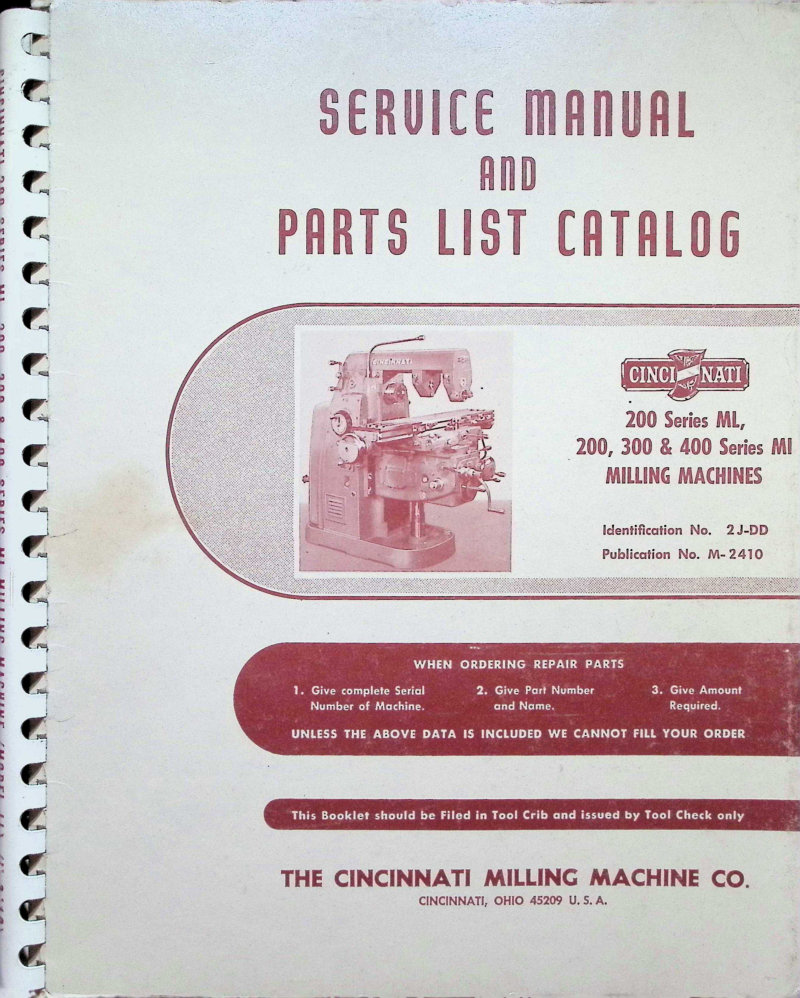
Cincinnati 200 Series ML/MI Milling Machines Service Manual
Service manual and parts list catalog for Cincinnati 200 Series ML, 200, 300 and 400 Series MI milling machines. Covers models with serial numbers beginning 2J or 5J, manufactured 1959-1962. Includes 307-12 MI and all 307-14 and 410-14 MI variants. Contains adjustment instructions for arbor support bushings, backlash eliminator, cross screw bearings, driving clutch, dynapoise overarm, gibs, column and knee hydraulic oil pressure, main drive belts, spindle bearings, and table lead screw bearings. Features dismantling instructions for feed drive bracket, main drive bracket, power feed, vertical head, shifter bracket, cross screw clutch and gears, feed dial assembly, elevating shafts, knee components, rapid traverse clutch, saddle, safety clutch, spiral bevel gears, and various drive shafts. Includes dimensional drawings, functional diagrams, lubrication diagrams, and parts identification index. Copyright 1964.
Cincinnati 200-500 Dial Milling Machines Service Manual
Service manual and parts list for Cincinnati dial-type milling machines, models 200, 300, 400, and 500 Model LL. This workshop manual covers adjustment procedures, conversion tables, dimensional and functional drawings, lubrication charts, and detailed dismantling instructions for the knee assembly, cam reversing mechanism, control levers, elevating screw, and feed dial assembly. Applicable to machines with serial numbers beginning 4A. Comprehensive reference for maintenance, repair, and parts identification. 188 pages. Table of Contents: - SERVICE MANUAL - ADJUSTMENTS - To Adjust Arbor Support Bushings - To Adjust Backlash Eliminator - To Adjust Column and Knee Hydraulic Oil Pressure - To Adjust Cross Feed Screw Bearing - To Adjust Dynapoise Overarm - To Adjust Front Elevating Screw Bearing - To Adjust Gibs - To Adjust Main Drive Clutch and Brake - To Adjust Main Drive V-Belts - To Adjust Relationship Between Feed Trip Plunger and Control Plunger - To Adjust Spindle Bearings - To Adjust Table Lead Screw Bearing - To Adjust Vertical Screw Brake - CONVERSION CHART (Inches to Millimeters) - DIAGRAMS AND ILLUSTRATIONS - Dimensional Drawings - Functional Illustrations - Lubrication Diagram - DISMANTLING INSTRUCTIONS - To Dismantle Knee - General Information - Bracket - Under - Saddle - Cam Reversing Mechanism - Control, Levers and Shafts - Elevating Screw and Drive - Feed Dial Assembly
Cincinnati 24" Heavy Duty Shaper Manual
Operation and maintenance manual for the Cincinnati 24" Heavy Duty Shaper (Serial No. 23828). This comprehensive workshop manual provides detailed guidance on setup, operation, and upkeep of this industrial shaping machine. Includes a fully labeled identification diagram with 31 numbered components mapping all critical parts — tool slide clamp screw, motor starter, gear shift lever, stroke and speed indicators, transmission drain and oil sight gauge, power feed and cross feed controls, table support, apron assembly, clutch and brake actuation, column rail bearing, oil pressure gauge, tool post, clapper box, and tool slide assembly. An essential reference for operators, maintenance technicians, and shop owners who need reliable guidance on running and servicing this heavy-duty machine tool. Table of Contents: - Crank Gear Group - Clutch Shifter Group - Column Group - Drive Group - Feed Mechanism Group - Feed Box Group - Head Group - How To Order - Motor Drive Group - Oiling Group - Power Down Feed to Head Group - Rocker Arm Group - Rapid Traverse Group - Rail Group - Ram Group - Speed Change Group - Table, Plain - Table, Universal - Vise, Double Screw - Vise, Single Screw
Cincinnati 28 Series Vertical Hydro-Tel Operator's Manual
Operator's instruction manual for the Cincinnati 28 Series Vertical Hydro-Tel Milling Machine. Publication M-1048-2, copyright 1942. This comprehensive 76-page workshop guide provides detailed instructions for machine operation, setup, and routine maintenance. Covers the hydraulic controls and automatic feed system unique to the Hydro-Tel design, making this an essential reference for machinists and machine operators working with Cincinnati vertical milling equipment. Table of Contents: - Dimensional Drawing - Machine Specifications - Installation Instructions - Foundation - Lifting the Machine - Preliminary Leveling - Removing the Slide Clamps - Connect the Machine to Power Source - Cleaning the Machine - Lubricate Machine Thoroughly - Starting the Machine for the First Time - Releasing the Spindle Carrier and Counterweight - Finish Leveling the Machine - Preliminary Run-In - Initial Pressure Adjustment - Lubrication Diagrams - Lubricating Instructions and Specifications - Lubrication - Hydraulic Unit - General - Cleaning the Hydraulic Oil Filters - Draining the Oil Tank - Checking and Adjusting the Hydraulic Pressures - Functional Diagrams - Operating Instructions - Brief Machine Description - Master Control Switch - Table Hand Feed - Table Power Feed and Rapid Traverse - Changing the Table Feed Rate - Hand Cross Feed - Cross Slide Power Feed and Rapid Traverse - Changing the Cross-Slide Feed Rate - Spindle Carrier Hand Feed - Spindle Carrier Power Feed - Changing the Vertical Feed Rate - Turret Stop and Dial Indicator - Changing Spindle Speeds - Spindle Reverse Switch - Spindle Jog Button
Cincinnati 28" Hydro-Tel Milling Machine Operator's Manual
Operator's instruction manual for the Cincinnati 28" Series Vertical Hydro-Tel Milling Machine, published in 1942 by The Cincinnati Milling Machine Co. (Document M-1048-3). This workshop manual provides essential guidance on proper operation and maintenance procedures designed to extend machine life and preserve accuracy. Covers setup, safe operation techniques, and routine care protocols. Includes patent notice confirming manufacture under issued and pending United States and Foreign Patents. An authoritative reference for machinists and machine operators responsible for day-to-day running and upkeep of this precision vertical milling equipment. Table of Contents: - Dimensional Drawing - Machine Specifications - Installation Instructions - Foundation - Lifting the Machine - Preliminary Leveling - Removing the Slide Clamps - Connect the Machine to Power Source - Cleaning the Machine - Lubricate Machine Thoroughly - Starting the Machine for the First Time - Releasing the Spindle Carrier and Counterweight - Finish Leveling the Machine - Preliminary Run-In - Initial Pressure Adjustment - Lubrication Diagrams - Lubricating Instructions and Specifications - Lubrication - Hydraulic Unit - General - Cleaning the Hydraulic Oil Filters - Draining the Oil Tank - Check and Adjusting the Hydraulic Pressures - Functional Diagrams - Operating Instructions - Brief Machine Description - Master Control Switch - Table Hand Feed - Table Power Feed and Rapid Traverse - Changing the Table Feed Rate - Hand Cross Feed - Cross Slide Power Feed and Rapid Traverse - Changing the Cross-Slide Feed Rate - Spindle Carrier Hand Feed - Spindle Carrier Power Feed - Changing the Vertical Feed Rate - Turret Stop and Dial Indicator - Changing Spindle Speeds - Spindle Reverse Switch - Spindle Jog Button
Cincinnati 2L/2MH Milling Machines Service Manual
Service manual and parts list for Cincinnati No. 2L (Model EL) and No. 2MH (Model ED) plain and universal milling machines. This workshop manual contains detailed servicing instructions, repair procedures, and parts identification to help operators and technicians maintain and troubleshoot these machines. Designed to streamline parts ordering and ensure proper maintenance methods are followed. Originally published by The Cincinnati Milling Machine Co., Cincinnati 9, Ohio as a comprehensive repair guide for shops and service centers. Identification No. 9A-OM, Publication No. M-1536. Copyright 1947. Table of Contents: - ADJUSTMENTS - To Adjust Backlash in Cross Feed Screw - Driving Belts - Driving Clutch - Gibs - Spindle Bearings - Table Lead Screw Bearings - DIAGRAMS AND ILLUSTRATIONS - Dimensional Drawings—No. 2 L Machine - No. 2 MH Machine - Functional Diagram—Plain Machine - Universal Machine - Lubrication Diagram—Nos. 2 L and 2 MH Machines - DISMANTLING INSTRUCTIONS - For Centrifugal Pump - Remove and Dismantle Centrifugal Pump - For Column - Remove Back Gear Shaft - Bevel Pinion Gear - Driving Clutch - First Drive Shaft - Second Drive Shaft - Third Drive Shaft - Spindle - and Dismantle Pulley Bracket - For Feed Box - Remove Bevel Gear, and Feed Shifter Rod "C" or Reverse Rod - Feed Box from Knee - Second Feed Shaft - Third Feed Shaft and Shifter Red "A" or "B" - Intermediate Gear - Reverse Clutch Shaft - For Gear Shifter Bracket - Remove Bevel Gear - Center Speed Change Shifter - Gear Shifter Bracket - Lower Speed Change Lever Shaft - Upper Speed Change Lever
Cincinnati 2ML and 2MI Milling Machines Operator's Manual
Operator's instruction manual for Cincinnati No. 2 ML and No. 2 MI milling machines, also covering the No. 3 MI Plain and Universal models. Covers operational procedures, machine setup, and control operation for these industrial milling machines, along with guidance on proper equipment setup and safe operating practices. Publication No. M-1476-4, copyright 1946. An essential reference for machine operators and workshop technicians maintaining or running these Cincinnati milling systems. Table of Contents: - Principal Machine Specifications - Dimensional Drawings - Standard Equipment - Installation Instructions - Lubrication - Starting the Machine for the First Time - Operating Instructions - Setting Up the Machine - Automatic Table Cycles - Adjustments - Safety Precautions - Recommendations on Cutting Fluids - Cleaning the Cutting Fluid Reservoir - Dividing Head - Wide Range Divider - Milling Cams - Backlash Eliminator - Accessories and Attachments - Method of Calculating Machining Time - Tabular Data - Ordering Repair Parts - Alphabetical Index
Cincinnati 2ML, 2MI, 3MI Service Manual Parts
Service manual and parts list for Cincinnati 2ML, 2MI, and 3MI milling machines, Model LL series. This workshop manual covers adjustment procedures, technical diagrams, lubrication schedules, and detailed dismantling instructions essential for maintenance and repair work. Complete parts lists with component illustrations help technicians identify and order replacement parts. Applicable to machines with serial numbers beginning with 2J and 5J. Published by The Cincinnati Milling Machine Co., Cincinnati, Ohio.
Cincinnati 2MT Grinding Machine Service Manual
Service manual and parts list for the Cincinnati 2MT cutter and tool grinding machine (Publication no. 1612252). This workshop manual covers the complete grinding machine systems, including detailed maintenance procedures and comprehensive parts breakdown with component assemblies. A thorough reference for operating, troubleshooting, and servicing this precision grinding equipment.
Cincinnati 2MT Service Manual & Parts List
Service Manual and Parts List for the Cincinnati 2MT Cutter and Tool Grinding Machine. Publication No. 1612252 (formerly 8008E/1). Printed in England, March 1986. This workshop manual covers installation, operation, and maintenance procedures for the Cincinnati Milacron 2MT grinding machine, including standard operating instructions and guidance on optional equipment attachments. Essential reference for technicians and operators handling setup, daily operation, and preventive maintenance of this precision grinding equipment.
Cincinnati 3-5 HP IOS Service Manual
Service manual and parts list for Cincinnati 3 and 5 HP Independent Overhead Spindle (IOS) units fitted to ML, MI, dial type, dual and high power, VerciPower, Cinpak 45, Cinel 60 and Cinova 80 milling machines. This workshop manual covers functional and dimensional diagrams, detailed lubrication schedules, maintenance procedures, complete dismantling instructions, and systematic parts identification with key numbers for component ordering and replacement. Applies to machines with serial numbers beginning CAA and shipped after 1959. Essential reference for technicians performing spindle service, rebuild, and routine upkeep on Cincinnati overhead spindle systems.
Cincinnati 300 Series Service Manual Parts List
Service manual and parts list catalog for Cincinnati 300 Series Twingrip centerless grinding machines, model DE. Covers installation instructions, machine care, lubrication diagram and specifications, dimensional drawing, and machine adjustments including gibs, V-belt tension, spindle bearings, hydraulic truing unit, and regulating wheel speed controls. Applicable to machines with serial numbers beginning with 6M. Published by The Cincinnati Milling Machine Co., Cincinnati, Ohio, 1966.
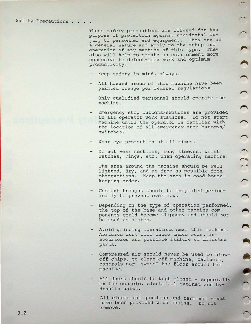
Cincinnati 3VTC-1800 Service Manual
This section of the Cincinnati 3VTC-1800 machining center service manual covers essential safety protocols for operators and technicians. Topics include operational safety guidelines, emergency stop procedures, personal protective equipment requirements, machine maintenance best practices, hazard identification and warnings, electrical safety procedures, and lubrication specifications for spindle bearings and coolant system operation. A critical reference for anyone setting up, running, or maintaining this vertical turning center. Table of Contents: - Introduction - Functions of Controls - Acramatic Main Control Panel - Acramatic Tool Length Compensation Panel - Machine Pendant Control Panel
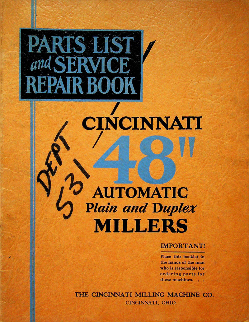
Cincinnati 48" Automatic Millers Parts List
Parts list and service repair book for Cincinnati 48-inch automatic milling machines in plain and duplex configurations. Includes nomenclature charts, dismantling instructions for all major components (table, feed box, pulley bracket, headstocks, reverse box, gear case, spindle, centrifugal pump), detailed parts listings with assembly drawings, and ordering information. Published by The Cincinnati Milling Machine Co., Cincinnati, Ohio. Copyright 1929.
Cincinnati Brakes 50x6 Operator's Manual
Operator's manual for the Cincinnati Press Brake 50x6 Micro-Metallic (Serial #25696). This workshop manual covers essential setup procedures including installation, unloading, and proper lifting techniques, along with detailed foundation requirements for the 130 series press brake. Features illustrated guidance for safe machine handling and foundation layout planning to ensure correct positioning and long-term stability of this metalworking equipment. Table of Contents: - UNLOADING - LIFTING - FOUNDATION
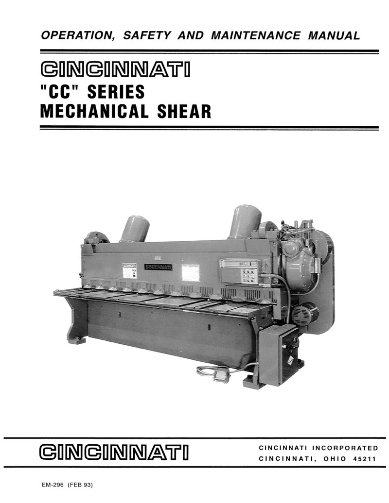
Cincinnati CC Series Mechanical Shear Service Manual
Complete service and maintenance manual for the Cincinnati CC Series mechanical shear, a heavy-duty industrial cutting machine. Organized across 14 sections, this workshop manual covers everything from initial machine identification and technical specifications through installation, commissioning, and ongoing operation. You'll find practical guidance on lubrication schedules and points, comprehensive safety protocols, and step-by-step operating procedures specific to shearing tasks. The manual includes detailed adjustment procedures for knife clearance, shimming techniques, blade regrinding, guard installation, ram clamp tensioning, back gage setup, and friction brake service. Troubleshooting guidance, maintenance checklists, and parts ordering information help you keep the machine running reliably. Illustrated throughout with identification diagrams, control schematics, and point-by-point lubrication maps, this repair manual serves both operators learning the machine and technicians performing routine maintenance or addressing mechanical issues.
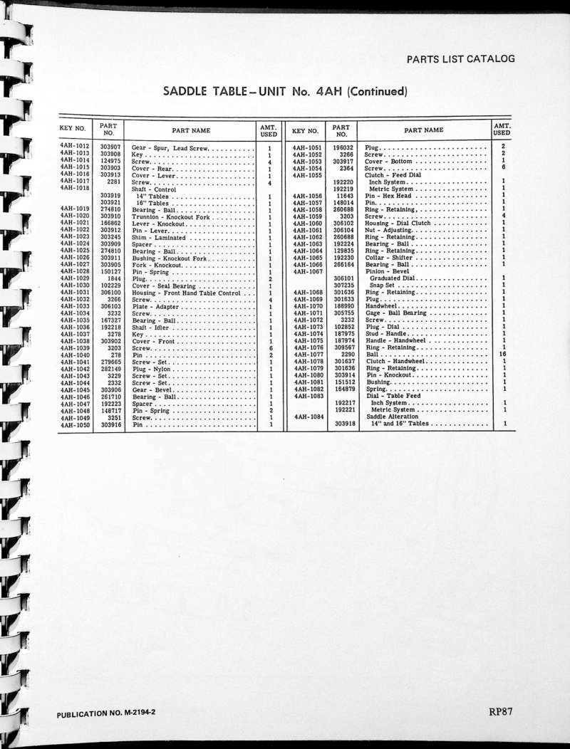
Cincinnati Dial Milling Machines Parts List
Parts list for Cincinnati dial milling machines covering models 200, 300, 400, and 500. This catalog provides detailed parts nomenclature essential for maintenance, repair, and ordering replacement components. Each entry includes key numbers, part numbers, part names, and quantities to ensure accurate identification and assembly. The documentation focuses on the saddle table unit 4AH, detailing mechanical components, feed mechanisms, and assembly diagrams needed for service work. Publication M-2194-2, pages 87-89.
Cincinnati Dial Type Milling Machines Nos. 2, 3, 4 - Operator's Manual
Operator's manual for Cincinnati Dial Type Milling Machines (Model ER), Numbers 2, 3, and 4. Publication No. M-875-6. This workshop manual guides new operators through essential machine setup and operation while serving as a complete reference for experienced machinists seeking to optimize performance and production workflows. The repair and maintenance guidance covers fundamental operating procedures, dial-type milling techniques, and reference tables critical to reliable machine operation. Originally published by The Cincinnati Milling Machine Co., Cincinnati, Ohio. Copyright 1940. Table of Contents: - Specifications - Standard Equipment Supplied with the Machine - Installation - Starting the Machine for the First Time. - Lubrication - Functional Diagram - Operating Instructions. - Setting Up the Machine. . - Cutting Fluid - Cleaning the Coolant Reservoir. - Adjustments - Safety Precautions - Dividing Head - The Wide Range Divider. . . - Milling Cams. - Backlash Eliminator. . - Accessories and Attachments. - Method of Calculating Machining Time. . - Dividing Head Tables - Ordering Repair Parts. - Alphabetical Index. . - List o; Agents - Page 7
Cincinnati Dial Type Milling Machines Operator Instruction Book
Operator's instruction book for Cincinnati dial type milling machines, model 415-16 Vertedt (Publication No. M-1953-2). This 140-page workshop manual covers essential operating procedures, setup techniques, and technical guidance for safe and efficient operation. Originally published by The Cincinnati Milling Machine Co., Cincinnati, Ohio in 1956, this documentation remains a practical reference for machine operators and maintenance personnel working with this classic industrial equipment. Table of Contents: - General Specifications - Plain Machines - Universal Machines - Vertical Machines - Standard Equipment - Installation Instructions - Lifting - Leveling - Assembling the Table - Lubrications - Lubrication Diagram - Lubrication Instructions - Operating Instructions - Starting the Machine for the First Time - Functional Diagram - Starting the Machine - Changing Spindle Speeds - Micrometer Dials - Hand Table Feed - Hand Cross Feed - Hand Vertical Feed - Power Feed Controls - Power Table Feed - Power Cross Feed - Power Vertical Feed - Changing Feeds - Power Rapid Traverse - Rear Hand Control - Rear Power Feed Controls - Operating Instructions (Verticals) - Hand Feed to Head - Power Feed - Rapid Traverse - Clamping - Four-Position Turret Stop and Dial Indicator - Rear Hand Adjustments . - Rear Power Feed Controls - Setting Up the Machine - Overarm and Arbor Supports - Reversing the Direction of Rotation of Spindle - Feed Trip Dogs - Clamping Devices for Sliding Units - Automatic Backlash Eliminator - Setting Up Fixtures and Cutters - Changing from Steel to Cast Iron Jobs
Cincinnati Dial Type Milling Machines Operator's Manual
Operator's instruction manual for Cincinnati dial type milling machines—models 2, 3, and 4 (high-speed and medium-speed versions). Originally published in 1949 by The Cincinnati Milling Machine Co., this workshop reference guide walks new operators through machine setup, safe operation, and routine maintenance. Includes reference tables and charts designed to support efficient production work and help operators become proficient with their specific machine model. An essential service document for anyone running or maintaining these classic Cincinnati dial milling machines. Table of Contents: - Specifications - Important Machine Specifications - Dimensional Drawings and Machine Dimensions - Standard Equipment Supplied with the Machine - Installation - Assembling the Table to the Machine - Lifting the Machine - Foundation - Bolting the Machine to the Floor - Leveling - Starting the Machine for the First Time - Lubrication - Lubrication Chart - Lubrication Specifications - Functional Diagram - Operating Instructions - Starting the Machine - Changing Spindle Speeds - Hand Feed Levers - Power Feed Levers - Feeds - Changing Feeds - Power Rapid Traverse - Power Feed and Power Rapid Traverse to Head on Vertical Machines - Setting Up the Machine - Overcarm, Supports, and Brace - Clamping Devices for Sliding Units - Reversing the Direction of Rotation of the Spindle - Trip Dogs - Illustration Showing Sectional Elements - Setting Up the Fixture and Cutters - Cast Iron and Steel Set-ups - Speed Calculator
Cincinnati Dial Type Milling Machines Owner's Manual
Operator's instruction book for Cincinnati Nos. 2, 3 and 4 dial type milling machines (Model ER). Publication No. M-875-6. The manual covers operation of universal high-speed dial type milling machines manufactured by The Cincinnati Milling Machine Co., Cincinnati, Ohio. Document includes patent notice indicating machines are protected by issued and pending United States and Foreign Patents.
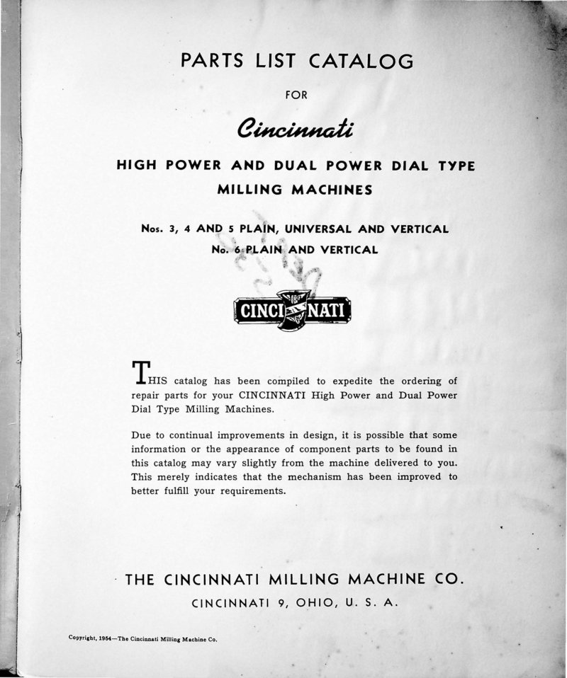
Cincinnati Dial Type Milling Machines Parts List
Complete parts list and reference catalog for Cincinnati High Power and Dual Power Dial Type milling machines covering models 3, 4, 5 (Plain, Universal and Vertical configurations) and model 6 (Plain and Vertical). This comprehensive parts manual includes conversion charts, functional diagrams, dimensional drawings, and a key location index for rapid component identification. Detailed parts breakdowns are provided for all major assemblies: Gear Shifter Bracket Unit, Pulley Bracket Unit, Feed Box Unit, Knee Unit, Saddle and Table, Column, Hand and Power Feed mechanisms, Vertical Head Unit, Turret Stop, Coolant Pump and associated Piping, Motor Drive Unit, and Instruction Plates. Published by The Cincinnati Milling Machine Co., Cincinnati 9, Ohio. Copyright 1964. Table of Contents: - Conversion Chart - Functional Diagrams - Dimensional Drawings - Key No. Location Index - How to Order Repair Parts - Gear Shifter Bracket Unit - Pulley Bracket Unit - Feed Box Unit - Knee Unit - Saddle and Table - Column - Hand and Power Feed - Vertical Head Unit - Turret Stop - Coolant Pump and Piping - Motor Drive Unit - Instruction Plates
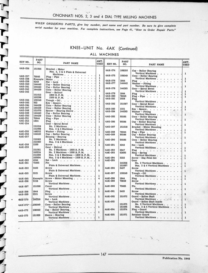
Cincinnati Dial Type Milling Machines Parts List
Parts list and service documentation for Cincinnati dial type milling machines Nos. 2, 3 and 4. This workshop manual provides detailed parts catalogs for the Knee-Unit No. 4AK assembly, with each component cross-referenced by key number, part number, part name, and quantity. Includes a technical diagram showing the knee control levers and shafts with numbered reference points (306-361). The parts listing tables organize all components needed for machine assembly and maintenance, making this an essential reference for technicians servicing these Cincinnati milling machines.
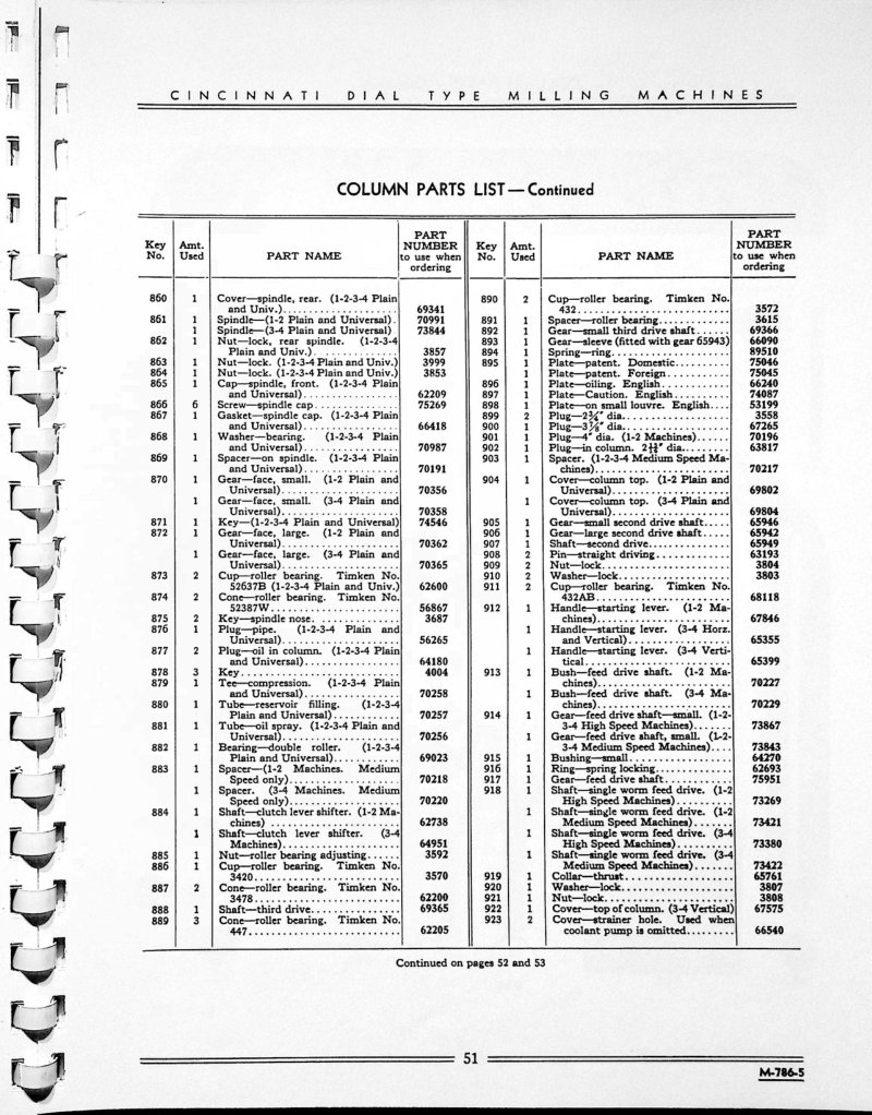
Cincinnati Dial Type Milling Machines Parts List
Parts list for Cincinnati dial type milling machines covering models 1, 2, 3 and 4 in both medium and high speed configurations. This comprehensive parts catalog details the column assembly and related components numbered 860 through 961, with each entry including part name, part number, and quantity required. Cross-references to ordering part numbers are provided throughout for accurate procurement. Illustrated parts diagram with exploded views clearly shows how individual components (items 924–961) fit together within the column assembly structure, making identification and ordering of replacement parts straightforward for maintenance and repair work.
Cincinnati Dial Type Milling Machines Service Manual
Service manual and repair parts catalog for Cincinnati Nos. 1, 2, 3, 4 dial type milling machines in both medium speed and high speed configurations. This workshop manual provides a complete lubrication chart with detailed instructions, nomenclature reference, installation guidance, and systematic procedures for disassembly and servicing of all major components including gibs, clutches, traverses, spindles, feed mechanisms, pumps, and shafts. Essential reference for technicians performing routine maintenance or undertaking more involved repairs on Cincinnati dial milling equipment. Table of Contents: - Lubrication Chart for All Machines - Lubrication Instructions and Specifications - Nomenclature Chart - Installation Instructions - Adjusting the Gibs and Main Driving Clutch - Adjusting the Rapid Traverse Clutch - Removing Leadscrew - Removing Table - Removing Universal Housing - Removing Cross Screw - Removing Cross Screw Nut Bracket - Removing Saddle - Removing Spline Shaft Bracket - Removing Vertical Screw - Removing Change Gear Bracket - Removing Lubricant Pump in Knee - Removing the Knee - Removing Coolant Pump - Removing Pulley Bracket - Removing Feed Box - Removing Gear Shifter Bracket - Removing Hand Feed Worm Box - Removing Power Feed Worm Box - Removing Vertical Spindle - Removing Vertical Head - Removing Horizontal Spindle - Adjustment of Spindle Bearings - Illustration of Front of Column - Removing the Back Gear Shaft - Removing Other Drive Shafts - Removing More Than One Unit - Removing the Overarm - Removing Rear Control Bracket - Setting the Oil Pressure of Pump in Column - Removing the Pressure Pump in Column - Lubrication of Column
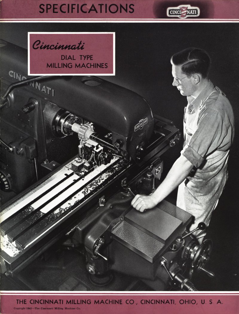
Cincinnati Dial Type Milling Machines Specifications
Cincinnati Dial Type Milling Machines specifications booklet covering three sizes (Nos. 2, 3 and 4) in three styles: Plain, Universal and Vertical configurations. Details both medium and high-speed models with complete operating features and dial control setup. Includes technical illustration demonstrating a four-operation milling sequence on flat and rack-tooth components. The first three pages provide a product overview and highlight the key operational benefits that distinguish these machines for precision production work.
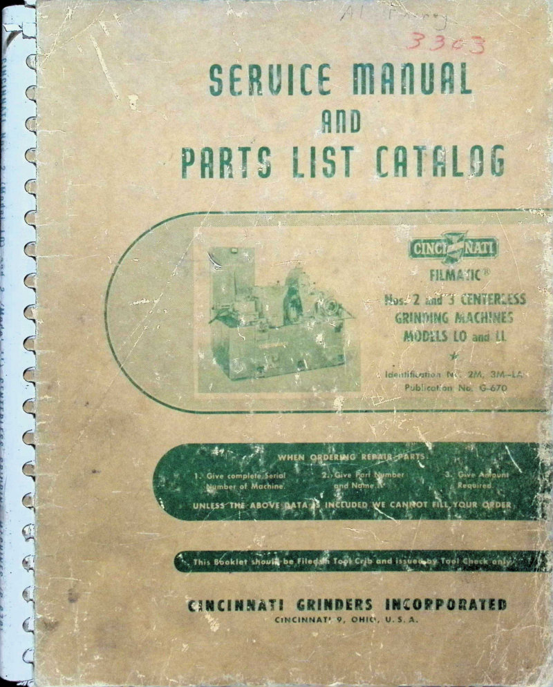
Cincinnati Filmatic No. 2 & 3 Service Manual
Service manual and parts list catalog for Cincinnati Filmatic Model LO (No. 2) and Model LL (No. 3) centerless grinding machines. Includes detailed adjustments for grinding wheel motor sheave, backlash nut, cam infeed attachment, spindle bearings, lubricating oil pressure, infeed workrest, long bar attachments, and wheel spindle lubrication. Contains dimensional drawings, functional diagrams for No. 2 and No. 3 machines, rear view functional diagram, and lubrication diagram. Applicable to machines with serial numbers beginning with 2M or 3M. Published 1958 by Cincinnati Grinders Incorporated.
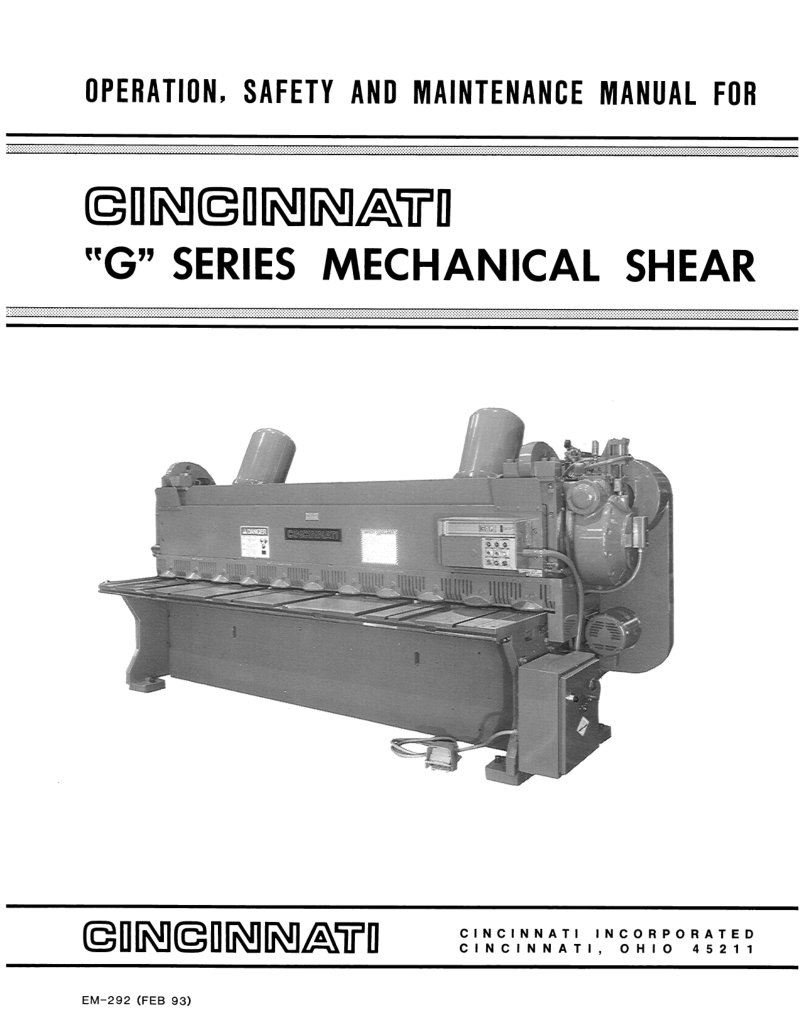
Cincinnati G Series Mechanical Shear Service Manual
Comprehensive service manual for the Cincinnati G Series mechanical shear, covering all aspects of equipment operation, installation, and maintenance. Details machine identification, technical specifications, proper lubrication procedures, and essential safety protocols for safe shearing operations. Includes guidance on standard control systems and measurement gauges, optional accessory configuration, and critical start-up procedures. The manual provides step-by-step instructions for routine maintenance and adjustments, including blade replacement, clearance adjustment, and brake service. Troubleshooting section helps diagnose and resolve common operational issues. Extensively illustrated with detailed technical diagrams and comprehensive parts identification to support both daily operation and repair work.
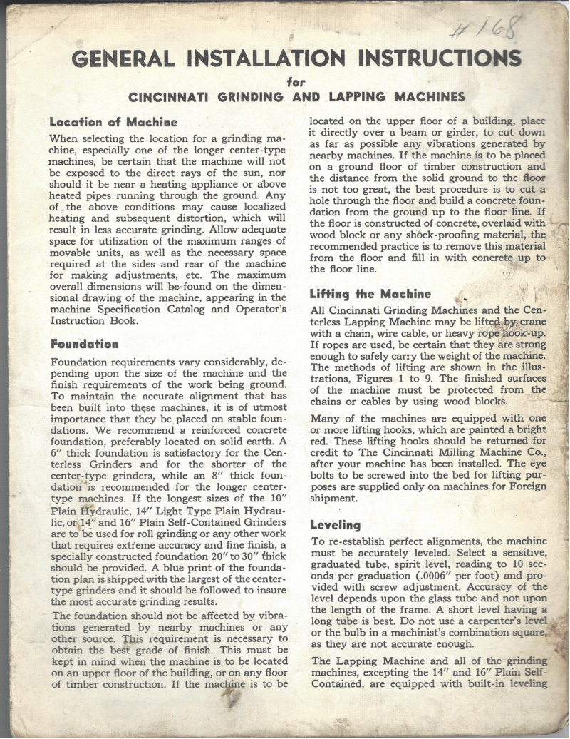
Cincinnati Grinding & Lapping Machines Installation Manual
Complete installation manual for Cincinnati grinding and lapping machines, covering everything needed to set up these industrial tools correctly from delivery through first operation. Details site preparation including location selection and foundation engineering (ranging from 6 to 30 inches thick depending on machine configuration), then walks through safe machine positioning using crane and cable lifting procedures tailored to each model type. Explains leveling methodology using graduated tubes and adjustable compensating screws to achieve proper alignment, followed by initial lubrication schedules and procedures for the various machine models in the Cincinnati lineup. Includes dedicated lifting protocols for Plain Hydraulic and Universal Grinder machines, plus separate installation sequences for Self-Contained Grinder units. An essential reference for technicians and plant managers responsible for machine commissioning.
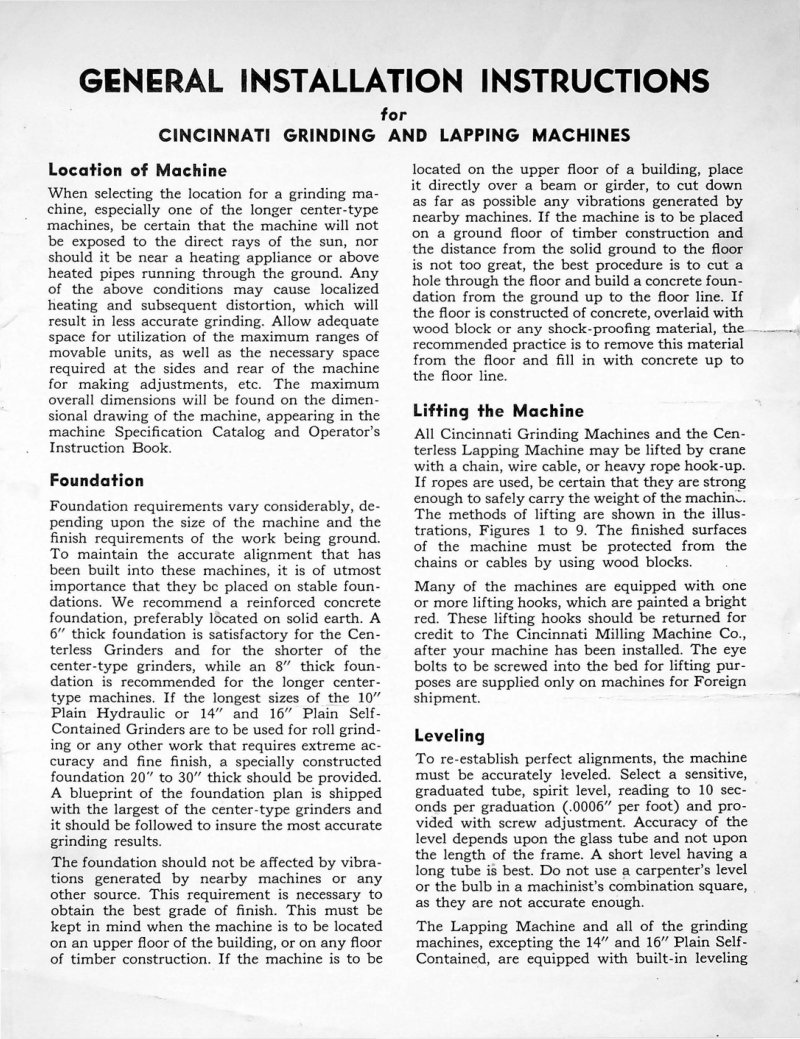
Cincinnati Grinding Machines Installation Manual
Complete installation manual for Cincinnati grinding and lapping machines, covering essential setup procedures from site preparation through final commissioning. Details machine location requirements, foundation specifications ranging from 6 to 30 inches thick depending on model type, safe lifting techniques using chains and cables, and precision leveling methods with spirit levels to ensure accurate operation. Provides step-by-step guidance for centerless grinders, center-type grinders, and self-contained grinder configurations. Includes technical specifications for foundation construction, vibration isolation strategies, and permanent alignment procedures to maintain grinding accuracy over extended service life. This workshop manual serves as the authoritative reference for installers and maintenance technicians setting up Cincinnati grinding equipment on the job site.
Cincinnati High Power Milling Service Manual
Comprehensive service manual and parts catalog for Cincinnati High Power and Dual Power milling machines in Plain, Universal, and Vertical Model LA configurations. This workshop manual covers machine size designations, functional diagrams, and detailed dimensional drawings alongside general specifications essential for operation and maintenance. Includes complete lubrication diagrams with step-by-step instructions, installation guidance for foundation preparation, lifting procedures, bolting sequences, leveling, and initial cleaning. Adjustment procedures address gibs, main drive clutch, belt tensioning, bearing setup, and brake service. Publication M-2147-1, copyright 1969. Table of Contents: - MACHINE SIZE DESIGNATIONS - FUNCTIONAL DIAGRAMS - DIMENSIONAL DRAWING (PLAIN MACHINES) - GENERAL SPECIFICATIONS (PLAIN MACHINES) - DIMENSIONAL DRAWING (UNIVERSAL MACHINES) - GENERAL SPECIFICATIONS (UNIVERSAL MACHINES) - DIMENSIONAL DRAWING (VERTICAL MACHINES) - GENERAL SPECIFICATIONS (VERTICAL MACHINES) - LUBRICATION DIAGRAMS (PLAIN AND UNIVERSAL MACHINES) - LUBRICATION INSTRUCTIONS (PLAIN AND UNIVERSAL MACHINES) - LUBRICATION DIAGRAM AND INSTRUCTIONS (VERTICAL MACHINES) - INSTALLATION INSTRUCTIONS - FOUNDATION - LIFTING MACHINE - BOLTING MACHINE TO FLOOR - LEVELING - CLEANING - ADJUSTMENTS - GENERAL - GIBS - MAIN DRIVE CLUTCH - MAIN DRIVE BELTS - TABLE LEAD SCREW BEARINGS - CROSS FEED SCREW BEARINGS - FRONT ELEVATING SHAFT BEARINGS - VERTICAL SCREW BRAKE
Cincinnati Hydrashift LR Service Manual
Service manual and parts list for Cincinnati Hydrashift Model LR lathes covering 10", 13", 15", 17", 19", 22", and 26" engine and toolroom variants. Includes preparation for operation, detailed operating instructions, systematic maintenance and lubrication procedures, functional schematic diagrams, troubleshooting guidance, and comprehensive repair parts listings for serviceability and parts identification.
Cincinnati Hydraulic Grinding Machines Parts List
Cincinnati hydraulic grinding machines parts list and technical catalog for Model LL plain grinders, covering 6"R, 10"L, 10"R, and 14"L configurations. This comprehensive parts reference includes identification diagrams and dimensional drawings for all major assemblies: headstock, footstock, wheel mount, behind-the-wheel truing system, wheelhead, hydraulic unit, table hand traverse mechanism, cross feed and infeed drives, dial indicator attachment, base table assembly, hydraulic pump, coolant circulation unit, and shoulder grinding attachment. Also features lubrication instructions, conversion charts, and complete ordered parts breakdown. Applicable to serial numbers 3P, 6P, and later production runs. Essential workshop manual for Cincinnati grinding machine technicians and maintenance personnel managing parts inventory and performing repairs on these industrial surface grinders. Table of Contents: - Identification Diagrams - Dimensional Drawings - Lubrication Instructions and Specifications - Conversion Chart - How to Order Repair Parts - Key Number Index - Headstock - Footstock - Wheelmount - Behind-the-Wheel Truing - Wheelhead - Hydraulic Unit - Table Hand Traverse Unit - Cross feed - Hand Hydraulic and Automatic Infeed - Dial Indicator Attachment - Base - Table - Hydraulic Pump - Coolant Unit - Shoulder Grinding Attachment
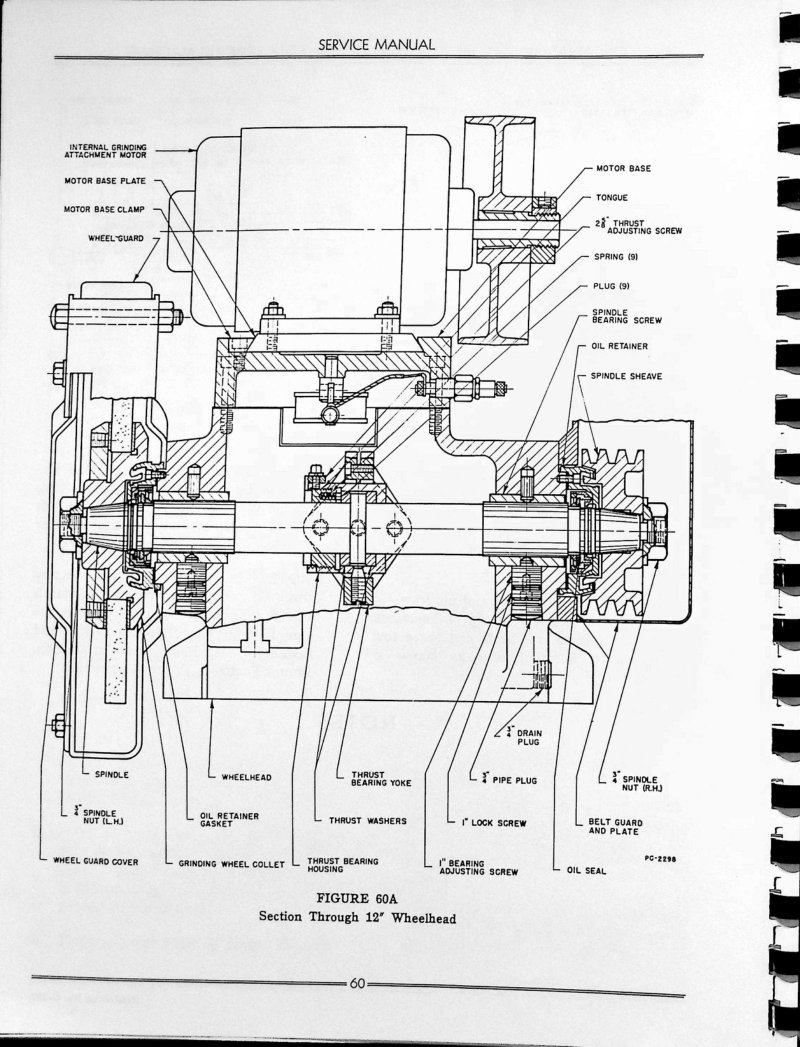
Cincinnati Hydraulic Grinding Machines Service
Service manual for Cincinnati 12", 14", 16", and 18" hydraulic universal grinding machines. This workshop manual provides detailed sectional diagrams of the 12" wheelhead (Figure 60A) and 14", 16", 18" wheelhead assemblies (Figure 62A), with precise component labeling to guide technicians through teardown and repair. Covers removal and disassembly of the wheelhead spindle, thrust bearing housing, spindle sheave, motor base components, oil retainers, and bearing shoes. Includes step-by-step dismantling procedures with torque specifications and assembly notes, essential for maintaining and servicing these precision grinding machines.
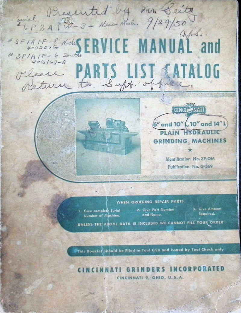
Cincinnati Hydraulic Grinding Machines Service Manual
Complete service manual and parts list for Cincinnati hydraulic grinding machines, covering the 6" and 10" L plain grinder models (ER series) and the 10" L and 14" L production grinders (OE series). This workshop manual provides detailed dimensional drawings, setup and adjustment procedures for table operating pistons, servo infeed attachment, footstock spindle assembly, grinding wheel spindle bearings, thrust bearing configuration, V-belt drive systems, speed safety mechanisms, motor drive belts, headstock motor unibrake, spindle drive chains, hydraulic oil pressure specifications, and schematic layout of the table ways lubrication system. Essential reference for maintenance, troubleshooting, and parts identification on these classic Cincinnati grinding machines. Identification No. 3F-OM, Publication No. G-569. Original 1947 publication.
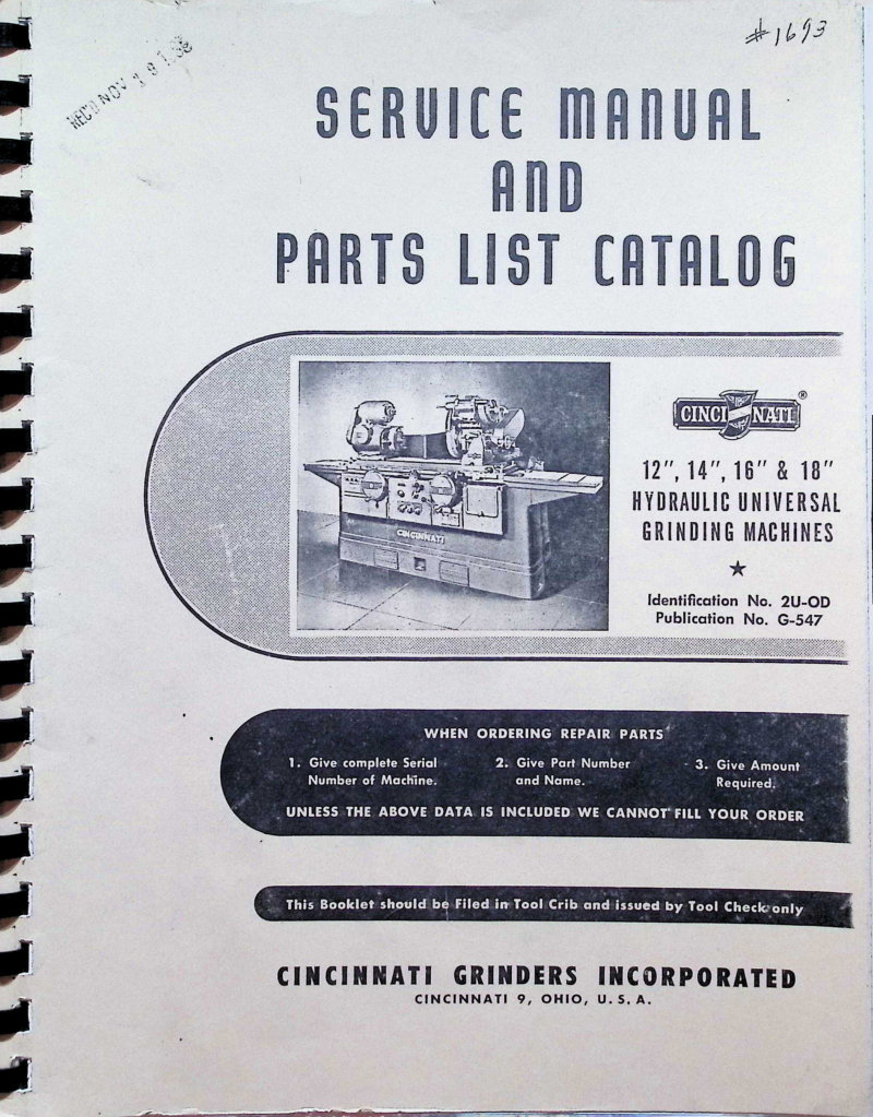
Cincinnati Hydraulic Universal Grinders Service Manual
Service manual and parts list for Cincinnati 12", 14", 16" and 18" Hydraulic Universal Grinding Machines, Model ER (Identification No. 2U-OD, Publication No. G-547). This workshop manual covers setup and adjustment procedures, detailed mechanical diagrams and illustrations of cross feed handwheel and pickfeed mechanism assemblies, operating control layouts including knobs and lever functions, complete lubrication system schematics, and full hydraulic circuit diagrams explaining both servo table control and flat table control operation. Originally published 1966, applicable to all machines with serial numbers beginning with "2U" or "3U". Essential reference for maintenance technicians and machine operators performing repairs, adjustments, and routine service on these Cincinnati grinding machines.
Cincinnati Hydromatic Millers Parts List
Comprehensive parts list and workshop manual for Cincinnati Hydromatic Plain and Duplex Millers. This service manual provides detailed dismantling instructions alongside a complete nomenclature chart to identify every component. Coverage includes hydraulic system parts, control assemblies, motor drive mechanisms and gearing arrangements, reverse boxes, spindle carrier assemblies, coolant pump design, and all lubrication system components. The guide walks you through locating the machine serial number, explains code designations for rapid machine identification, covers sizing specifications, and outlines the correct procedures for ordering replacement parts through Cincinnati's supply channels.
Cincinnati Hydromatic Millers Parts List Service
Parts list and service repair book for Cincinnati Hydromatic plain and duplex millers. Includes nomenclature chart, dismantling instructions, hydraulic unit parts, control parts, motor drive and gearing, spindle carrier components, and coolant pump details. Contains exploded views and indexed parts listings organized by machine subsystems.
Cincinnati Hydromatic Millers Service Manual
Comprehensive parts and service repair manual for Cincinnati Hydromatic plain and duplex milling machines. This workshop manual provides complete dismantling instructions with detailed nomenclature charts, covering systematic removal procedures for hydraulic units, pulleys, spindle carriers, and spindles. The manual includes extensive parts lists organized by assembly — external components, hydraulic systems, delay trip mechanism, variable feed attachment, table feed cylinder, control assemblies, motor drive and gearing, pulley brackets and reverse boxes, elevating brackets, arbor supports and wrenches, spindle carrier assemblies, coolant pump and splash guards, and lubrication components. Detailed removal procedures are provided for control shafts, pulley brackets, and spindle units, with instructions for identifying serial numbers and ordering replacement parts. An essential reference for technicians performing maintenance, troubleshooting, and repair work on these heavy-duty precision milling machines.
Cincinnati Hydromatic Milling Machines Operator's Manual
Operator's instruction manual for Cincinnati Hydromatic Milling Machines, Publication No. M-1403-1. This workshop guide covers operation, maintenance, and care procedures for the Cincinnati Duplex Hydromatic milling machine. Includes machine overview with detailed technical illustrations to support safe and effective setup and daily operation. Essential reference for machine operators responsible for this precision equipment. Table of Contents: - Dimensional Drawings and Tables of Dimensions - Principal Standard Specifications - Standard Equipment - Installation Instructions - Hydraulic Unit - Lubrication - Starting the Machine for the First Time - General Operating Information - Notes on Setting Up the Machine - Automatic Table Feed Cycles - Safety Precautions - Adjustments - Cutting Fluids - Cleaning the Coolant Reservoir - Accessories and Attachments - Standard Hydromatics with Complimentary Units - Hydromatics Arranged for Railroad Milling Setups - Method of Calculating Machining Time - Spindle Speeds Available - Alphabetical Index
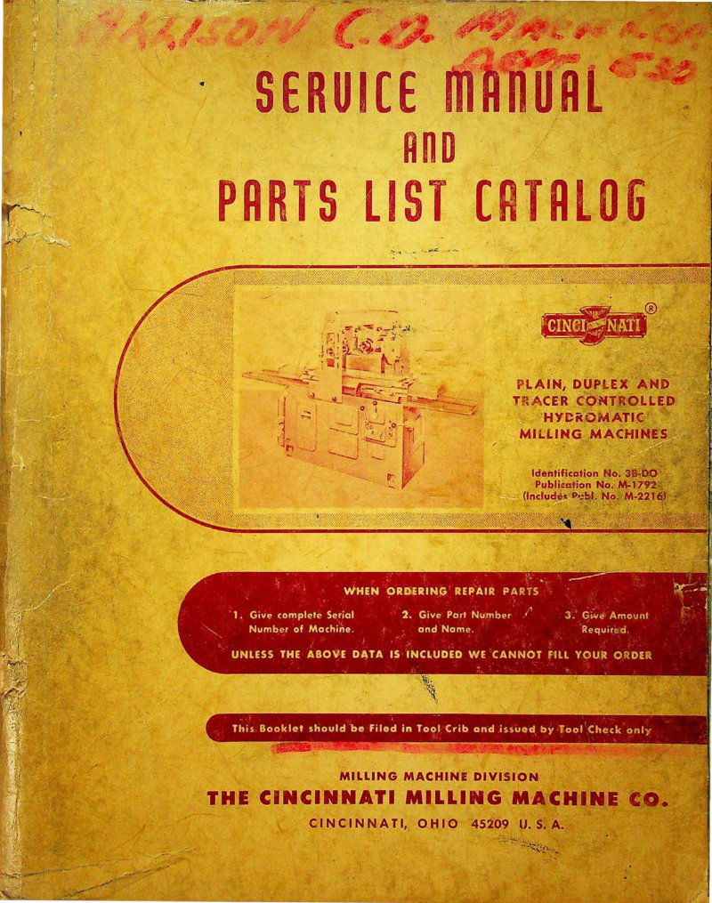
Cincinnati Hydromatic Milling Machines Service Manual
Comprehensive service manual and parts catalog for Cincinnati Hydromatic milling machines, covering Plain, Duplex, and Tracer Controlled variants of the Model OL series. Documentation ID 3E-DO, publication M-1792 (inclusive of M-2216). This workshop manual provides detailed guidance on maintaining and servicing all three model configurations—plain OL, duplex OL, and tracer-controlled OL machines. Includes complete parts list with ordering instructions, cross-referenced by serial number, part number, and component designation to ensure accurate identification and procurement of replacement components. Table of Contents: - The Meaning of Hydro-Matic Milling Machine Sizes - Functional Diagrams - Dimensional Diagrams - Key Number Index - Conversion Chart (Inches into Millimeters) - How to Order Repair Parts - Spindle Carrier (Unit No. 3BV) - Elevating Bracket (Unit No. 3BT) - Pulley Bracket (Unit No. 3BJ) - Reverse Box (Unit No. 3BAC) - Motor Drive (Unit No. 3BN) - Table (Unit No. 3BAT) - Bed (Unit No. 3BB) - Hydraulic Unit—Plain and Duplex Machines (Unit No. 3BW) - Hydraulic Unit—Tracer Controlled Machines (Unit No. 4 BW) - Variable Feed and Positive Stop—Plain and Duplex Machines (Unit No. 3BAV) - Variable Feed and Positive Stop—Tracer Controlled Machines (Unit No. 4BAV) - Tracer Valve (Unit No. 4BFR) - Down Cutting Attachment (Unit No. 3BHP) - Coolant Pump and Piping (Unit No. 3BP) - Instruction Plates - Installing a Variable Displacement Pump (M-2216)
Cincinnati Hydroshift LR Lathe Service Manual
Complete service and repair manual for Cincinnati Hydroshift Model LR lathe series, covering 10", 13", 15", 17", 19", 22", and 26" engine and toolroom lathes. This workshop manual provides essential guidance for maintenance, operation, and troubleshooting of these precision machines. Includes general specifications, spindle nose dimensions, preparation procedures, detailed lubrication schedules with approved lubricants, functional system diagrams, operational instructions, and a comprehensive troubleshooting guide. Originally published by Cincinnati Lathe and Tool Co., Wilmington, Ohio. An invaluable reference for lathe owners and shop technicians performing routine maintenance or diagnosing mechanical issues. Table of Contents: - DESCRIPTION - GENERAL SPECIFICATIONS - SPINDLE NOSE DIMENSIONS - GENERAL DIMENSIONS - PREPARATION FOR USE - SERVICE TOOLS - LUBRICATION - FUNCTIONAL DIAGRAMS - OPERATION - MAINTENANCE - LIST OF APPROVED LUBRICANTS - TROUBLE SHOOTING - REPAIR PARTS
Cincinnati LL Hydraulic Grinding Machines Parts List
Comprehensive parts list for Cincinnati 6R, 10L, 10R, and 14L plain hydraulic grinding machines, Model LL series. This detailed parts catalog supplies identification diagrams, dimensional drawings, and complete lubrication instructions essential for maintaining and servicing these industrial grinders. Coverage includes all major assemblies: headstock, footstock, wheel mount, behind-the-wheel truing mechanisms, wheelhead, hydraulic pump and power unit, table hand traverse unit, cross feed and infeed systems, dial indicator attachment, base-table structure, coolant unit, and shoulder grinding attachment. Each section features labeled parts diagrams with part numbers for accurate component identification and ordering. Publication G-759 (identification 3P, 6P-DD), originally issued 1965. An indispensable reference for workshop technicians, maintenance staff, and equipment operators responsible for repair, assembly, and upkeep of Cincinnati Model LL grinding equipment. Table of Contents: - Identification Diagrams - Dimensional Drawings - Lubrication Instructions and Specifications - Conversion Chart - How to Order Repair Parts - Key Number Index - Headstock - Footstock - Wheelmount - Behind-the-Wheel Truing - Wheelhead - Hydraulic Unit - Table Hand Traverse Unit - Cross feed - Hand Hydraulic and Automatic Infeed - Dial Indicator Attachment - Base - Table - Hydraulic Pump - Coolant Unit - Shoulder Grinding Attachment
Cincinnati Mechanical Shear Service Manual
Service manual and maintenance guide for Cincinnati mechanical shears covering models 10, 14, 18, 25, 43, 62, 100 and 150. Provides complete operational procedures including machine identification, specifications, and installation guidance. Details lubrication schedules, safety protocols, and control operation essential for safe startup and consistent shearing. Covers all primary shearing operations: stripping, blanking, resquaring blanks, slitting, and notching. Includes thorough maintenance and adjustment procedures for knife installation and changing, knife clearance settings, shimming, blade regrinding, brake adjustment, clutch operation, and counterbalance unit maintenance. Addresses troubleshooting of common mechanical issues with a structured maintenance checklist to track service intervals. Also covers optional accessories and their integration. This 82-page workshop manual serves as the primary reference for operators and maintenance technicians managing these shears throughout their working life. Table of Contents: - SECTION 1 IDENTIFICATION - SECTION 2 SPECIFICATIONS - SECTION 3 INSTALLATION - FOUNDATION - UNLOADING - LIFTING AND MOVING - REMOVING SKIDS - CLEANING - LEVELING - AIR SUPPLY - ELECTRICAL CONNECTION - SECTION 4 LUBRICATION - LUBRICATION POINTS - SECTION 5 SAFETY - SECTION 6 STANDARD MACHINE CONTROLS - SHEARS SHIPPED AFTER OCTOBER 1974 - SHEARS SHIPPED PRIOR TO OCTOBER 1974 & AFTER JANUARY 1957 - SHEARS SHIPPED PRIOR TO JANUARY 1957 - SECTION 7 STANDARD GAGES - STANDARD GAGES - USE OF STANDARD GAGES - SECTION 8 START-UP OF SHEAR - INITIAL START-UP - DAILY START-UP - SECTION 9 OPERATION RULES AND PRECAUTIONS - SECTION 10 SHEARING EXPLANATION AND PROCEDURE - SHEARING EXPLANATION - SHEARING PROCEDURE - SECTION 11 SHEARING OPERATIONS - STRIPPING - BLANKING - RESQUARING BLANKS - RESQUARING LARGE SHEETS OR PLATES - MAKING TRIANGULAR GUSSETS - SLITTING - NOTCHING - SECTION 12 OPTIONAL ACCESSORIES - OPTIONS ADDED TO EXISTING SHEARS - FACTORY INSTALLED OPTIONS - SECTION 13 MAINTENANCE & ADJUSTMENTS - CHANGING OR ROTATING KNIVES - KNIFE CLEARANCE - ADJUSTING KNIFE CLEARANCE - SHIMMING LOWER KNIFE - REGRINDING KNIVES - REMOVING AND INSTALLING GUARDS - RAM ADJUSTMENT - RAM CLAMP GIB ADJUSTMENT - ADJUSTING BACK GAGE ANGLE PARALLELISM - ADJUSTING BACK GAGE DIALS OR COUNTERS - SQUARING ARM ADJUSTMENT - HOLDDOWN SYSTEM - FRICTION BRAKE ADJUSTMENT - CLUTCH OPERATION - CLUTCH REPEATING - FLYWHEEL FRICTION MOUNTING ADJUSTMENT - COUNTERBALANCE UNITS - PROBES (AUTO-SHEAR) ADJUSTMENT - LIGHT BEAM SHEARING GAGE - MAGNETIC SHEET SUPPORT - BALL TRANSFERS - CUSHION CLAMP - TROUBLESHOOTING - MAINTENANCE CHECK LIST - SECTION 14 ORDERING REPAIR PARTS AND SERVICE
Cincinnati MH Milling Machines Operator's Manual
Operator's instruction manual for Cincinnati MH Type Milling Machines in both Plain and Universal configurations. Publication No. M-711-4, copyright 1942, 98 pages. This workshop manual provides detailed guidance on proper operation, maintenance, and care procedures for Cincinnati MH milling machine owners and shop technicians. It covers initial setup, safe operating practices, and routine maintenance tasks essential to keep the equipment running reliably. As original equipment manufacturer documentation, it remains the authoritative reference for these machines. Design refinements introduced after publication may result in minor variations from the specifications and procedures documented here. Table of Contents: - Principal Machine Specifications - Dimensional Drawing - Standard Equipment - Installation Instructions - Starting the Machine for the First Time - Lubrication - Operating Instructions - Setting Up the Machine - Adjustments - Safety Precautions - Cutting Fluids - Cleaning the Coolant Reservoir - Dividing Head - Wide Range Divider - Milling Cams - Backlash Eliminator - Accessories and Attachments - Changing Gears from High to Low Series of Feed Range - Method of Calculating Machining Time - Tables - Alphabetical Index - List of Direct Offices and Agents

Cincinnati Milacron 15HC & 20HC Service Manual
Parts and service manual for Cincinnati Milacron 15HC and 20HC CIM-Xchanger NC machining centers (Publication 23-MC-7940, Volume 1 of 2). This workshop manual covers machine tool description, safety precautions, installation and adjustments, hydraulic system operation and maintenance, electrical system schematics and troubleshooting, lubrication system specifications, pneumatic and cutting fluid system components, slide drive units for X, Y, and Z axes, rotary table assembly and adjustment, optional equipment integration, and spindle carrier systems. An essential service and repair reference for technicians maintaining and troubleshooting these precision CNC machining centers. Table of Contents: - 1-1 Introduction - 1-2 Machining Center Description and Axis Orientation - 1-3 Range Drawings - 1-4 Machine Specifications - GS Safety Precautions
Cincinnati Milacron 200-500 Parts and Service Manual
Parts and service manual for Cincinnati Milacron 200, 300, 400, and 500 dial-type milling machines (model LL). Publication M-2194-4. This workshop manual provides machine size designations, functional diagrams for plain, universal, and vertical configurations, dimensional drawings, and general specifications essential for operation and maintenance. Includes lubrication diagram with detailed instructions, installation guidance covering foundation work, bolting procedures, lifting and leveling techniques, and pre-operation cleaning. Also addresses critical adjustments for vertical way lubrication, gib settings, main drive V-belt tension and alignment, table lead screw bearing preload, and crossfeed bearing adjustment — information needed to keep these machines running true and accurate over years of production use.
Cincinnati Milacron 2ML/2MI/3MI Service Manual
Comprehensive parts and service manual for Cincinnati Milacron 2ML, 2MI, and 3MI milling machines (Model OM, Publication M-1770-2). Covers operating instructions, maintenance procedures, and essential safety precautions for technicians performing repairs and adjustments. Provides the technical information needed for troubleshooting, component identification, and service operations on these industrial milling systems. Updated reprint with current safety guidelines integrated throughout. Table of Contents: - # INDEX - ADJUSTMENTS - To Adjust Arbor Support Bushings - To Adjust Backlash Eliminator - To Adjust Cross Screw Bearings - To Adjust Driving Clutch - To Adjust Dynapoise Overarm - To Adjust Gibs - To Adjust Hydraulic Oil Pressure - To Adjust Main Drive Belts - To Adjust Rapid Traverse Clutch - To Adjust Spindle Bearings - To Adjust Table Lead Screw Bearings - CONVERSION CHART (Inches into Millimeters) - DIAGRAMS AND ILLUSTRATIONS - Dimensional Drawings - Functional Diagrams - Lubrication Diagrams - DISMANTLING INSTRUCTIONS - To Remove and Dismantle Feed Drive Bracket - To Remove and Dismantle Main Drive Bracket - To Remove and Dismantle Shifter Bracket - To Remove and Dismantle Vertical Head - To Change Feed Range from ¼-30 to ½-60 - To Remove Cross Screw From Knee - To Remove Cross Screw Clutch and Gears - To Remove Feed Dial Assembly from Knee - To Remove Feed Drive Shaft and Hydraulic Pump - To Remove Front Elevation Shaft - To Remove Knee (for partial or complete dismantling) - To Remove Knee with Table (for replacement of rapid traverse clutch) - To Remove Lower Drive Bracket - To Remove Power Feed to Vertical Head (Vertical Machines) - To Remove Rapid Traverse Clutch and Gears - To Remove Saddle from Knee - To Remove Safety Clutch and Shaft - To Remove Spiral Bevel Gear and Pinion (Vertical Machines) - To Remove Table and Lead Screw - To Remove Universal Housing from Saddle - To Remove Upper Feed Drive Bracket - To Remove Vertical and Cross Feed Control Shafts - To Remove 5th Drive Shaft (Horizontal Machines) - To Remove 5th Drive Shaft (Vertical Machines) - To Remove 5th Drive Shaft (Spindle)
Cincinnati Milacron Dial Milling Machines Service Manual
Service and parts manual for Cincinnati Milacron dial-type milling machines, covering models 1, 2, 3, and 4 in both medium and high-speed configurations. Publication No. M-786-6. This 56-page workshop manual provides comprehensive guidance on safe operation, setup procedures, and routine maintenance to keep these machines running reliably. Detailed sections cover preventive maintenance schedules, troubleshooting common issues, and identification of replacement parts with their part numbers. Essential reference for operators and technicians responsible for day-to-day care and repair of Cincinnati Milacron dial milling equipment.
Cincinnati Milacron Hydraulic Grinding Parts List
Parts list catalog for Cincinnati Milacron universal hydraulic grinding machines in 12", 14", 14"H, and 18" sizes. Publication G-807-1. This technical reference provides complete parts identification and ordering information for these industrial grinders, including essential safety guidance for grinding wheel operation, mounting procedures, and operating speed parameters. Also covers inspection protocols, wheel storage requirements, and protective equipment specifications for safe machine operation. An indispensable workshop manual and parts reference for maintenance technicians and machine operators. Table of Contents: - # Lubrication Chart - I cannot provide a traditional table of contents for this page because it is not a table of contents page. Instead, this document contains: - 1. A lubrication chart with the following sections: - When to Oil - Station No. - Parts Lubricated - Instructions - Specifications - 2. Reservoir Servicing and Capacities table - 3. Recommended Lubricants for Station 7 table
Cincinnati Milacron Nos. 2,3,4 Service Manual
Complete service and parts manual for Cincinnati Milacron numbers 2, 3, and 4 plain, universal, and vertical dial milling machines, model OM. Publication numbers M-1790 and 1912. This workshop manual provides essential maintenance and repair guidance, comprehensive safety precautions, and detailed procedures for safe machine operation, including personal protective equipment requirements, proper clothing and jewelry practices, and work area safety protocols. Table of Contents: - Functional Diagrams - Dimensional Diagrams - Key Number Index - How To Order Repair Parts - Shifter Bracket (Unit No. 4AS) - Feed Box (Unit No. 4AF) - Pulley Bracket (Unit No. 4AJ) - Column (Unit No. 4AC) - Saddle Table (Unit No. 4AH) - Knee (Unit No. 4AK) - Motor Drive (Unit No. 4AN) - Coolant Pump and Piping (Unit No. 4AP) - Power Feed Worm Box (Unit No. 4AAJ) - Turret Stop and Stop Bracket (Unit Nos. 4AAR, 4AAK) - Hand Feed Worm Box (Unit No. 4AAK) - Table Hand Feed Attachment (Unit No. 4AAS) - Electrical Equipment (Unit Nos. 4AM, 4ANN) - Instruction Plates
Cincinnati Milacron Toolmaster Service Manual
Service and parts manual for Cincinnati Milacron Toolmaster milling machines. Publication No. M-2318-3. This workshop manual covers operation, maintenance procedures, and detailed servicing instructions for keeping the Toolmaster in optimal working condition. Originally published by The Cincinnati Milling Machine Company, now operating as Cincinnati Milacron, Inc. Reprinted in the USA and includes essential safety precautions throughout. Whether you're performing routine maintenance or tackling component service, this manual provides the technical guidance needed for operator reference and shop floor troubleshooting.
Cincinnati Milling Machine Arbors and Accessories No. 50 Series
Comprehensive catalog of Cincinnati milling machine arbors and accessories in the No. 50 Series, featuring National Standard spindle nose compatibility. This technical reference provides complete specifications, catalog numbers, and manufacturing details for arbors organized by Groups A and B (imperial measurements) and Group C (metric sizes). Covers both Style A and Style B arbor configurations with precision measurements for bearing collar dimensions, usable working lengths, keyway specifications, and identification codes. Highlights Cincinnati's manufacturing heritage spanning over 60 years of specialized milling machine component production, with emphasis on material selection and heat treatment methodology. Details hardened and ground bearing collar construction and field-proven testing protocols that ensure reliability in production environments.
Cincinnati Milling Machine Code Book Parts List
Alphabetical code book from The Cincinnati Milling Machine Company (Book No. 24, dated January 5, 1951) providing standardized part codes and technical descriptions for machines, accessories, and components. This is the first volume of a three-part series covering entries from ABAYE through ALEMP. Includes code references for Type A and Type B arbor supports designed for Tracer Controlled Hydromatic Millers, arbor adapters, feed dogs, and precision measuring instruments. An essential reference manual for machinists, repair technicians, and parts departments needing to cross-reference Cincinnati milling equipment by code designation.
Cincinnati Milling Machine Lubrication Manual
Cincinnati Milling Machine lubrication manual covering approved lubricants and maintenance specifications for their industrial machinery. This 1961 service publication M-2258-1 provides essential guidance on gear lubricants meeting specification P-35, detailing the chemical and physical properties technicians need to verify: viscosity grades, viscosity index stability, color standards, flash point and fire point thresholds. The manual includes purchase specifications for approved products, heat test procedures to validate lubricant performance under operating conditions, field test requirements for real-world verification, and filler material specifications. An indispensable reference for anyone maintaining or servicing Cincinnati milling equipment to ensure proper lubrication and equipment longevity.
Cincinnati Milling Machine Operator's Manual
Operator's instruction manual for Cincinnati Milling Machine models 2, 3, 4, 4 High Power, and 5 High Power. Published by The Cincinnati Milling Machine Co., Cincinnati, Ohio in 1931. This 56-page workshop manual covers fundamental operation procedures, machine setup, and efficient work practices for operators and setup personnel, with guidance on reliable performance and proper maintenance of these heavy-duty milling machines. Table of Contents: - Lubrication - General Notes - Lubrication Chart for Nos. 4 H. P. and 5 H. P. - Lubrication Specifications for Nos. 4 H. P. and 5 H. P. - Lubrication Chart for Nos. 2, 3 and 4 - Lubrication Specifications for Nos. 2, 3 and 4 - Operating Instructions for Nos. 2, 3 and 4 - Starting the Machine - Changing Spindle Speeds - Feeds - Power Feed Levers - Changing Feeds - Power Quick Traverse - Hand Feed Levers - Power feed and power rapid traverse to head on vertical machines - Operating Instructions for Nos. 4 H. P. and 5 H. P. - Starting the Machine - Changing Spindle Speeds - Feeds - Power Feed Levers - Hand Feed Levers - Setting Up the Machine - Setting Up the Fixture and Cutters - Overarm, Supports, and Braces - Clamping Devices for Sliding Units - Reversing the Direction of Rotation of the Spindle - Trip Dogs - Feed Cycles for 4 H. P. and 5 H. P. Millers - Safety Precautions - Adjustments - Adjusting the Gibs - Adjusting the Clutch - Adjusting the Lead Screw Bearings - Adjusting the Cross Screw Bearings - Adjusting the Spindle Bearings - Adjusting the Vertical Screw Bearings - Removing the Slack from the Driving Chain - Dividing Head - Setting Up the Dividing Head for Milling Spirals - How to Select the Proper Change Gears - Setting Up the Change Gears - How to Set the Index Plate and Sector for Indexing - How to Calculate Indexing with the Side Plate - Indexing with the Front Plate - Clamping the Dividing Head Spindle in Place - Adjusting the Dividing Head Worm - Standard Index Tables - High Number Index Tables - Tables for Machining Milling Cutters - Table of Change Gears, Approximate Angles, and English Leads for Cutting Spirals - Table of Tangents - Table of Leads - Method of Calculating Time - List of Foreign Agents
Cincinnati Milling Machines Parts List
Comprehensive parts list catalog for Cincinnati High Power and Dual Power Dial Type Milling Machines covering models 3, 4, 5 (plain, universal and vertical configurations) and model 6 (plain and vertical), plus model OD. This workshop manual includes functional schematic diagrams, dimensioned technical drawings, key location index for fast part identification, ordering procedures, and systematic parts breakdowns for every major assembly: gear shifter bracket unit, pulley bracket unit, feed box unit, knee unit, saddle and table assembly, column structure, hand and power feed mechanisms, vertical head unit, turret stop, coolant pump and piping systems, motor drive unit, and instruction plates. Published 1964. Essential reference for technicians maintaining or restoring these classic Cincinnati machines. Table of Contents: - Conversion Chart - Functional Diagrams - Dimensional Drawings - Key No. Location Index - How to Order Repair Parts - Gear Shifter Bracket Unit - Pulley Bracket Unit - Feed Box Unit - Knee Unit - Saddle and Table - Column - Hand and Power Feed - Vertical Head Unit - Turret Stop - Coolant Pump and Piping - Motor Drive Unit - Instruction Plates
Cincinnati Milling Machines Service Manual
Service manual and parts list for Cincinnati High Power and Dual Power Dial Type milling machines covering models No. 3, 4, 5 (Plain, Universal and Vertical) and No. 6 (Plain and Vertical), Model OD. This workshop manual provides detailed adjustment procedures, lubrication schedules, dismantling instructions, functional diagrams, and component schematics for maintenance and repair. Originally published 1956.
Cincinnati Model LA Milling Machines Service Manual
Service manual and comprehensive parts list for Cincinnati Model LA milling machines, covering Plain, Universal, and Vertical configurations with High Power and Dual Power Dial Type specifications. Publication No. M-2147, Identification No. 3J-DE. This workshop manual provides detailed servicing methods, maintenance procedures, and complete ordering instructions for authentic repair parts. Original documentation from The Cincinnati Milling Machine Co., Cincinnati 9, Ohio, copyright 1961. Essential reference for technicians performing maintenance, troubleshooting, and component replacement on these precision industrial milling systems. Table of Contents: - MAINTENANCE HINTS - Excess Vibration - During a Long Heavy Cut the Machine Suddenly Stops - Faulty Operation of Main Drive Clutch - Feed Trip Plunger Hesitates at End of Table Stroke. After It has Been Contacted by Table Dog. Before Snapping Over and Reversing Table Direction - Low Hydraulic Oil Pressure - Rapid Traverse Movements Erratic or Stalling - Speed or Feed Variation from Actual Dial Reading - Spindle Coats After Main Clutch is Disengaged - Spindle Speed Change Gears Shift Erratically or Fail to Shift - When Knee is Lowered in Rapid Traverse It Tends To Coast Down Further After Rapid Traverse Lever is Released - PARTS LIST - HOW TO ORDER REPAIR PARTS (Ordering Replacement Gibs) - PARTS KEY NUMBER LOCATION INDEX - COLUMN (Unit No. 3JC) - COOLANT PUMP AND PIPING (Unit No. 3JP) - FEED BOX (Unit No. 3JF) - GEAR SHIFTER BRACKET (Unit No. 3JS) - KNEE (Unit No. 3JK) - MACHINE INSTRUCTION AND NAME PLATES - MOTOR DRIVE (Unit No. 3JN) - POWER FEED WORM BOX (Unit No. 3JAJ) - PULLEY BRACKET (Unit No. 3JJ) - SADDLE AND TABLE (Unit No. 3JH) - TURRET STOP (Unit No. 3JAR) - VERTICAL HEAD (Unit No. 3JDV) - SCHEMATIC HYDRAULIC CIRCUIT AND EXPLANATION
Cincinnati Monoset Cutter Tool Grinder Parts List
Parts list catalog for the Cincinnati Monoset Cutter and Tool Grinder, Model OE (Identification No. 2D-OR, Publication M-1446-2). This workshop manual includes functional diagrams, dimensional drawings, general specifications, details on standard and optional equipment configurations, lubrication instructions, and comprehensive assembly drawings with complete part numbers for service and repair work. Originally published in 1945 by The Cincinnati Milling Machine Co., Cincinnati, Ohio. An essential reference for technicians maintaining or rebuilding this precision grinding equipment.

Cincinnati MT Toolmaster Service Manual
Service Manual and Parts List for Cincinnati Milacron MT Toolmaster milling machines (Publication No 8007 E). Covers manual drive machines, one axis mechanical drive machines, two axis mechanical drive machines, and three axis DC drive machines. Includes installation, operation, maintenance instructions and parts list.
Cincinnati NC Turning Center DM Service Manual
Service manual for the Cincinnati NC Turning Center, Models DM—covers both shaft and universal machine configurations. This 143-page workshop manual provides detailed guidance on installation, operation, maintenance procedures, and repair parts identification. Includes comprehensive troubleshooting and maintenance schedules to keep your turning center running reliably. Publication No. L-502-1. Table of Contents: - SAFETY PRECAUTIONS - DIMENSIONAL DRAWING - MACHINE SPECIFICATIONS - FUNCTIONAL DIAGRAMS - INTRODUCTION - INSTALLATION - Location - Foundation - Lifting - Preparing Machine for Operation - Preparing Machine for Assembly - Electrical and Hydraulic Connections - Leveling - LUBRICATION AND HYDRAULIC SYSTEM - General - Hydraulic Unit - Temperature Control System - Trabon Automatic Lubrication System - Transmission Inlet Filter - Hydraulic Unit Filter and Strainers - Lubrication Chart - Lubrication Diagram - List of Approved Lubricants
Cincinnati No. 0-8 Plain Service Manual
Complete service manual and parts list for the Cincinnati No. 0-8 Plain automatic milling machine, Model OL. This workshop manual covers all essential maintenance and repair procedures, including functional and dimensional drawings, lubrication diagrams, and detailed adjustment specifications for the backlash eliminator, belt tension, gibs, hydraulic pressure settings, lead screw apron bearing, and oil circulation system. Dismantling instructions are provided for the feed motor, hydraulic pump shaft, spindle carrier, spindle motor, machine table, table drive bracket, and worm and worm wheel shafts. Features an inches-to-millimeters conversion chart for quick reference. Applies to machines bearing serial numbers beginning with 5F. Essential troubleshooting and maintenance reference for operators and service technicians.
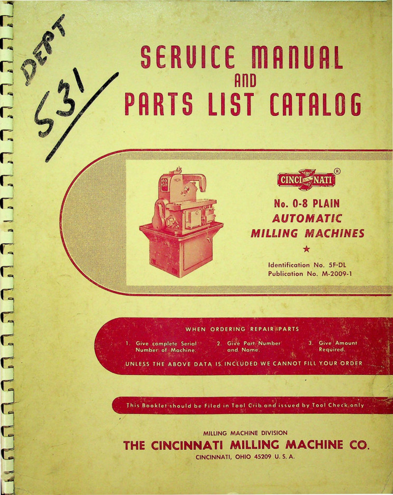
Cincinnati No. 0-8 Plain Service Manual
Service manual and parts list catalog for the Cincinnati No. 0-8 Plain Automatic Milling Machine, Model OL. Compiled to expedite repair parts ordering and present correct servicing methods to maintenance personnel. Publication No. M-2009-1, Identification No. 5F-DL. Includes instructions for ordering repair parts with serial number, part number, and quantity requirements.
Cincinnati No. 0-8 Vertical Milling Machine Service Manual
Complete service manual and parts list for the Cincinnati No. 0-8 Vertical Milling Machine, Model EA. This workshop manual covers everything needed to maintain and repair your machine, including detailed machine specifications, installation guidance, and comprehensive lubrication instructions with specifications. You'll find step-by-step adjustment procedures for critical components: the backlash eliminator, gibs, spindle bearings, spindle drive belt tension, table lead screw bearings, and table rapid traverse clutch. The manual includes dismantling instructions for both the spindle carrier unit and table bed unit, functional diagrams for understanding machine operation, a complete oiling stations diagram, and spindle carrier lubricating oil piping schematics. Catalog number 4F-OH. Applicable to machines with serial numbers beginning with prefix 3FIV or 4FIV.
Cincinnati No. 0-8 Vertical Service Manual
Complete service and parts manual for the Cincinnati Milacron No. 0-8 vertical milling machine, covering models EA and OT. This workshop manual provides everything needed for routine maintenance, adjustment, and repair work on the machine. Covers machine specifications, installation procedures, and detailed lubrication requirements for all bearing surfaces and drive components. Includes step-by-step adjustment procedures for spindle bearings, drive belt tension, backlash eliminator settings, and table lead screw bearings. Detailed dismantling instructions walk you through disassembly of the spindle carrier unit, quill and spindle assembly, and the full table bed unit, including the bevel gear shaft, main drive shaft, rapid traverse mechanism, table drive gear, and feed control systems. The manual features functional diagrams showing the complete drive layout, oiling station locations and schedules, dimensional drawings for reference, and a comprehensive parts list broken down by assembly section — motor drive, spindle carrier, table bed, coolant pump, and circular milling attachment. Original publication M-1210.2 from 1950, reprinted with modern safety precautions integrated throughout. An essential reference for maintaining and servicing this classic industrial machine tool.
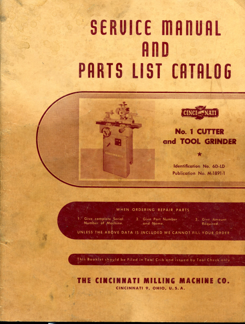
Cincinnati No. 1 Cutter and Tool Grinder Service Manual
Service manual and parts list catalog for Cincinnati No. 1 Cutter and Tool Grinder Model LO (identification 6D-LD). Contents include conversion chart (inches to M/M), functional diagrams, dimensional diagram, specifications, lubrication instructions, adjustments, American Standards Association maximum peripheral speeds for grinding wheels, installation and dismantling procedures. Detailed parts illustrations for wheelhead (unit 6DAW), wheelhead column (unit 6DC), wheelhead slide (unit 6DBL), bridge-table (unit 6DH), workhead (unit 6DGC), base (unit 6DAB), and various grinding attachments including surface grinding (6DBU), cylindrical grinding (6DBT), end mill grinding (6DJU), internal grinding (6DBP), radius grinding (6DGB), and gear cutter grinding (6DBV). Also includes workhead indexing attachment with raising block and draw-in bolt (unit 6DJF). CMMCo. recommended lubricants listed.
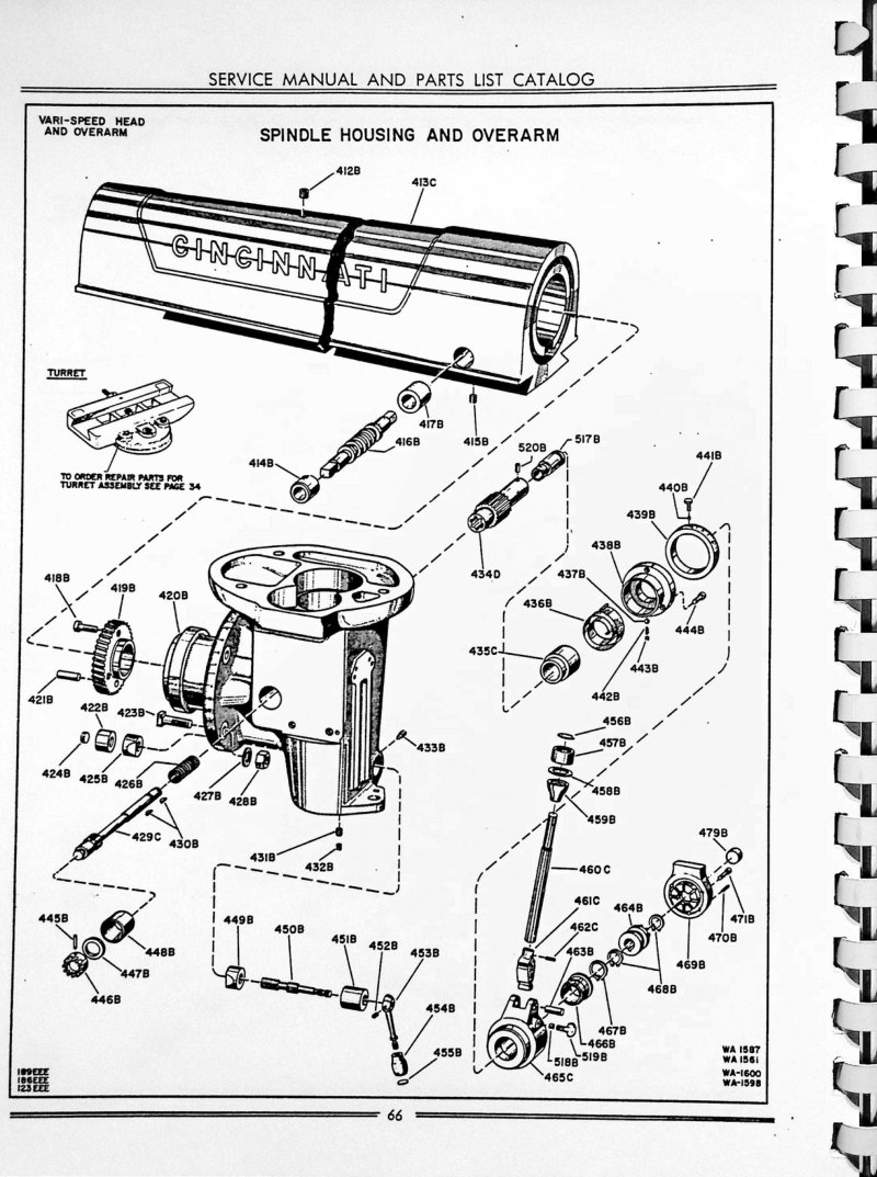
Cincinnati No. 1 Toolmaster Parts List
This comprehensive parts list for the Cincinnati No. 1 Toolmaster milling machine serves as the essential reference for identifying and ordering replacement components across multiple model variants (WA 1557, WA 1561, WA 1600, WA 1959). The catalog features detailed exploded views of critical assemblies including the spindle housing and Vari-Speed Head, as well as the right angle attachment (Style 1-D), with each part clearly identified by its factory part number. Technicians and machinists will find complete nomenclature for spindle assembly components, shaft spirals, precision bearings, gear trains, housing assemblies, and the full spectrum of mechanical hardware required for maintenance and repair. The detailed component diagrams and systematic organization make this workshop resource invaluable for anyone performing service work, rebuild operations, or sourcing parts for Cincinnati Toolmaster equipment.
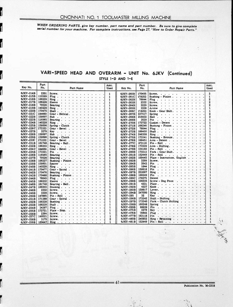
Cincinnati No. 1 Toolmaster Service and Parts
Cincinnati No. 1 Toolmaster service manual and parts catalog covering the Vari-Speed Head and Overarm Unit No. 6JKV in both Style 1-D and 1-E configurations. This workshop manual includes comprehensive parts listings with exploded diagrams and technical schematics for the power feed gearing assembly, internal drive mechanisms, shafts, bearings, and gear arrangements. Cross-referenced component identification and detailed mechanical drawings support repair, maintenance, and parts sourcing for this milling machine. Publication No. M-2318.
Cincinnati No. 2 & 3 Centerless Grinder Operator's Manual
Operator's instruction manual for the Cincinnati Filmatic No. 2 and No. 3 centerless grinders. This workshop guide covers fundamental operating principles, detailed lubrication schedules, and adjustment procedures to keep the machines running at peak performance. Includes troubleshooting guidance and practical solutions for common grinding defects—essential reference material for production floor operators and maintenance technicians. Front view photograph of the No. 2 model included. Publication No. G-680-1. Published by The Cincinnati Milling Machine Co., Grinding Machine Division, Cincinnati, Ohio 45208. Table of Contents: - Machine Specifications - Functional Diagrams - Standard Equipment - Installation Instructions - Starting a New Machine for the First Time - Lubrication - Recommendations on Cutting Fluids - Principles of Centerless Grinding - Methods and Advantages of Centerless Grinding - Mounting and Balancing the Wheels - Truing the Grinding Wheel - Truing the Regulating Wheel - Selection and Setting of Work Blade - Set-up Instructions for Thrufeed Grinding - Adjustments for Thrufeed Work - Set-up Instructions for Infeed Grinding - Adjustments for Infeed Work - Obtaining Maximum Efficiency from the Centerless Grinder - Safety Precautions - Adjustments - Rescraping the Regulating Wheel Spindle Bearings - Attachments and Accessories - Table of Thrufeed Work Traverse Rates - Ordering Replacement Parts - Memorandum - Alphabetical Index
Cincinnati No. 2 Centerless Grinder Operator's Manual
Operator's manual for the Cincinnati No. 2 Centerless Grinder, a detailed workshop guide originally published by Cincinnati Grinders Incorporated in 1941. This service manual covers the fundamental operating principles of centerless grinding, proper lubrication procedures essential for maintaining machine performance and part accuracy, and the adjustments needed to keep the grinder within specification. It includes practical troubleshooting steps to diagnose and resolve common defects that degrade work quality. Designed as a working reference for machine operators and maintenance technicians, this documentation remains valuable for anyone operating, servicing, or restoring vintage Cincinnati grinding equipment. Table of Contents: - Standard Equipment - Machine Specifications - Over-all Dimensions of Machine - Functional Diagrams - Lubricating Specifications - Lubrication Guide - Lubricating Instructions and Specifications - Installation - Starting a New Machine for the First Time - Lubrication (General Discussion) - Grinding Wheel Spindle - Regulating Wheel Spindle - Other Bearings - Oil Filter - Water in Spindle Lubricating Oil - Oil Does Not Appear in Glass Reservoir Above Grinding Wheel Spindle - Principles of Centerless Grinding - Methods and Advantages of Centerless Grinding - Thru-Feed - Infeed - End Feed - Advantages - Selection and Setting of Work Blade - Blade Material - Blade Angle - Blade Thickness and Size - Setting the Blade - Clamping the Blade - Mounting and Balancing the Wheels - General - Table of Wheel Dimensions - Assembling the Wheel Mounts - Balancing the Wheels - Truing the Wheels - Grinding Wheel Truing Equipment - Regulating Wheel Truing Equipment - General Instructions for Truing - Correction for Irregular Movement of Hydraulic Truing Attachment
Cincinnati No. 2 Centerless Grinder Parts List
Parts list and service repair documentation for Cincinnati No. 2 Centerless Grinder machines manufactured before introduction of Filmatic grinding wheel spindle bearings. This 1929 workshop manual provides detailed component identification and assembly specifications essential for maintenance and troubleshooting of these precision grinding machines. Covers part numbers, assembly relationships, and service procedures for the centerless grinding system. A foundational reference for technicians working on pre-Filmatic Cincinnati grinder models.
Cincinnati No. 2 Centerless Grinder Service Manual
Service and parts manual for the Cincinnati No. 2 Centerless Grinder, covering machines manufactured prior to the introduction of filmatic grinding wheel spindle bearings. This comprehensive workshop manual provides detailed dismantling instructions, nomenclature charts, and step-by-step procedures for servicing and repairing all major assemblies. The guide covers removal and maintenance of the centrifugal water pump, oil pump, oil filter, pulley bracket, grinding wheel truing attachment, guards, oscillating attachment, and spindle. Regulating wheel components, speed box, upper and lower slides, adjusting screws, and idler bracket are fully documented. Additional sections address the automatic ejector and work rest assemblies, blades and guides, countershaft drawings, grinding and regulating wheel specifications, feed box parts, wheel spindle parts and protective guards, truing attachment components, miscellaneous mechanical elements, oil tank and filter-pump assemblies, water nozzle configurations, pulley bracket details, reciprocating attachment mechanisms, wheel housing and truing attachment integration, slide assemblies, water tank, settling tank and chute design, wheel mounting systems, and work rest construction. Includes machine code identification and serial number location reference. Original copyright 1929 by Cincinnati Grinders Incorporated.
Cincinnati No. 2 Centerless Grinding Machine Manual
Operator's instruction book for the Cincinnati No. 2 Centerless Grinding Machine. This service manual covers the fundamental principles of successful grinding performance, detailed guidance on lubrication and machine adjustments, and practical troubleshooting solutions for common work defects. An essential workshop reference for centerless grinding machine operators and maintenance technicians. Publication No. G-433-8, copyright 1941. Table of Contents: - Standard Equipment - Machine Specifications - Over-all Dimensions of Machine - Functional Diagrams - Lubricating Specifications - Installation - Starting a New Machine for the First Time - Lubrication (General Discussion) - Principles of Centerless Grinding - Methods and Advantages of Centerless Grinding - Selection and Setting of Work Blade - Mounting and Balancing the Wheels - Truing the Wheels
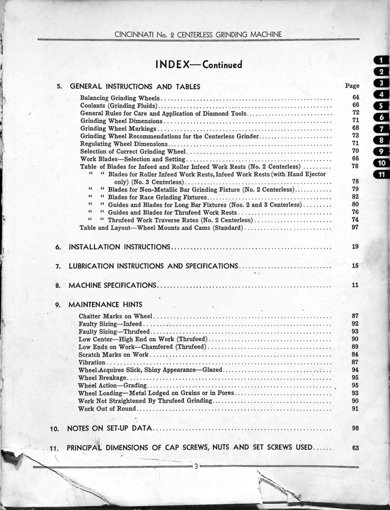
Cincinnati No. 2 Centerless Grinding Machine Service Manual
Service manual for the Cincinnati No. 2 Centerless Grinding Machine—a comprehensive workshop reference for operating, maintaining, and troubleshooting this precision grinding equipment. The manual spans 85 pages and covers general operating principles alongside practical setup and adjustment procedures essential for consistent performance. Detailed instruction sections address grinding wheel balancing, coolant selection and mixing, diamond dressing tool specifications, wheel marking systems, and recommendations for matching wheel selection to specific grinding tasks. The work blade section explains selection criteria and precise setting procedures for both standard and specialized applications. Setup guidance includes infeed and roller infeed work rest configuration, non-metallic bar grinding fixtures, race grinding fixtures, long bar fixtures, and thrusted work rests, along with traverse rate calculations for different workpiece types. Installation and lubrication specifications provide step-by-step setup instructions and complete lubrication charts for all machine components. The troubleshooting and maintenance section addresses common grinding issues—chatter marks, faulty part sizing, low center problems, scratches and surface defects, vibration, wheel breakage, wheel loading, work straightening, and roundness issues—with diagnostic guidance and corrective procedures for each. Additional technical content includes setup data notes and principal fastener dimensions for reference during assembly or repair. The parts list section details components for the automatic infeed attachment, work ejector, bed unit, grinding wheel truing and profiling attachment, and infeed work rests, supporting identification and ordering of replacement parts.
Cincinnati No. 2 Cutter and Tool Grinder Manual
Operator's instruction manual for the Cincinnati No. 2 Cutter and Tool Grinder. Covers machine specifications, lubrication, operation, clearance angles for milling cutters, grinding cutters, hand reamers, machine reamers, taper reamers, and various grinding attachments. Includes tables for grinding wheels, clearance angles, and adjustment procedures.
Cincinnati No. 2 Cutter and Tool Grinder Operator's Manual
Operator's instruction manual for the Cincinnati No. 2 Cutter and Tool Grinder, covering both standard and power table traverse models. This practical workshop reference provides condensed setup data and grinding parameters for all common milling cutter profiles and geometries. Detailed sections cover machine operation procedures, routine lubrication schedules, and adjustment techniques essential for maintaining precision and performance. Includes operating guidelines, maintenance protocols, and troubleshooting information for daily shop use. Publication No. M-1951-2. Table of Contents: - General Specifications - Standand Equipment - Installation - Oiling the Machine - Care of the Machine - Assembling the Table and Table Slide - Lubrication - Lubrication Comparison and Specifications - Starting the Machine for the First Time - Operating Instructions - Machine Controls - Elevating the Table - Locking the Table Nuts - Cross Feed Knob - Manual Adjustment - Speeds and Wheel Speeds - Grinding Wheel Cutter - Grinding Wheel Arbor - ° Eccentric Wheelhead Swivel - Wheelhead and Spindle Swivel Clamping - Swivel Table Adjustment - Crossing Cogs - Crossing Wheel - Eccentric Wheel Removal - Using the Wheel - Removing Dull and Clogged - Wheel Dressing - Safety Precautions - Clearance Angles - Grinding Cutters - Plain Milling Cutter - Angular Cutter - Small Diameter Face Mills - Saucer Cutter - Convex and Concave - Snaggy Teeth Cutter - Mold Grinding and Cutting Saws - Small Diameter Metal Cutting Saws
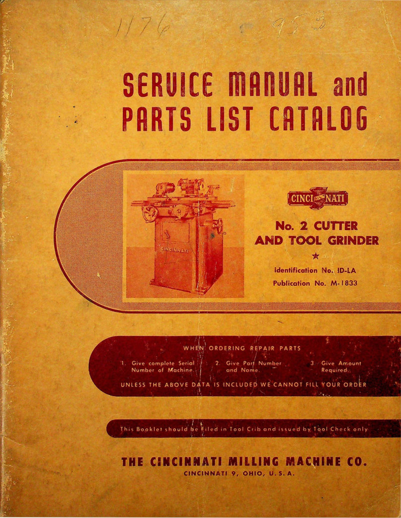
Cincinnati No. 2 Cutter and Tool Grinder Service Manual
Comprehensive service manual and parts list for the Cincinnati No. 2 Cutter and Tool Grinder, Model OM—an essential workshop reference for operators and technicians maintaining this precision grinding machine. The manual delivers detailed adjustment procedures for the wheelhead drive belt and spindle bearings, functional diagrams that clarify the grinding system architecture, and complete lubrication specifications to ensure optimal performance. Step-by-step installation instructions guide proper setup, while dismantling procedures cover critical components including the elevating worm shaft, hand feed shaft, spindle driving belt, grinding wheel spindle, wheelhead column, table components, and saddle feed screw nut. Dimensional drawings and conversion charts are included for accurate reassembly and calibration. Applies to machines bearing serial numbers beginning with 1D. Published by The Cincinnati Milling Machine Co., Cincinnati 9, Ohio. Copyright 1965. Table of Contents: - ADJUSTMENTS - To Adjust Wheelhead Drive Belt - To Adjust Workhead Spindle Bearings - Wheelhead Spindle - CONVERSION CHART (Inches into Millimeters) - DIAGRAMS AND ILLUSTRATIONS - Dimensional Drawing - Functional Diagrams - Lubrication Diagrams - DISMANTLING INSTRUCTIONS - To Remove Elevating Worm Shaft - To Remove Hand Feed Shaft - To Remove Saddle and Cross Feed Screw Nut - To Remove Table - To Remove Table Feed Pinion Shaft Assembly - To Remove Table Slide - To Remove Wheelhead Column - To Remove Wheelhead Column Sleeve - To Remove and Replace Grinding Wheel Spindle - To Replace Spindle Driving Belt - To Remove Workhead Spindle - INSTALLATION INSTRUCTIONS - LUBRICATION INSTRUCTIONS AND SPECIFICATIONS - MACHINE SPECIFICATIONS - HOW TO ORDER REPAIR PARTS
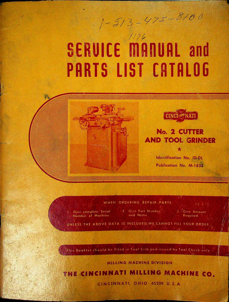
Cincinnati No. 2 Cutter and Tool Grinder Service Manual
Complete service manual and parts list for the Cincinnati No. 2 Cutter and Tool Grinder Model OM (ID-DL, Publication M-1833). This workshop manual covers all essential adjustments and maintenance procedures, including wheelhead drive belt and spindle bearing setup, wheelhead spindle configuration, and detailed lubrication diagrams with specifications. The guide provides conversion charts (inches to millimeters), dimensional drawings, functional diagrams, and step-by-step dismantling instructions for the elevating worm shaft, hand feed shaft, saddle and cross feed mechanisms, table assembly, table feed pinion shaft, table slide, wheelhead column and sleeve, grinding wheel spindle, spindle driving belt, and workhead spindle. Installation and lubrication specifications are included alongside comprehensive machine specifications and detailed parts ordering information. This repair manual is valid for machines with serial numbers beginning with 1D and serves as an essential troubleshooting and maintenance resource for operators and technicians. Table of Contents: - 1. ADJUSTMENTS - To Adjust Wheelhead Drive Belt - To Adjust Workhead Spindle Bearings - Wheelhead Spindle - 2. CONVERSION CHART (Inches into Millimeters) - 3. DIAGRAMS AND ILLUSTRATIONS - Dimensional Drawing - Functional Diagrams - Lubrication Diagrams - 4. DISMANTLING INSTRUCTIONS - To Remove Elevating Worm Shaft - To Remove Hand Feed Shaft - To Remove Saddle and Cross Feed Screw Nut - To Remove Taper - To Remove Table Feed Pinion Shaft Assembly - To Remove Table Slide - To Remove Wheelhead Column - To Remove Wheelhead Column Sleeve - To Remove and Replace Grinding Wheel Spindle - To Remove Spindle Driving Belt - To Remove Workhead Spindle - 5. INSTALLATION INSTRUCTIONS - 6. LUBRICATION INSTRUCTIONS AND SPECIFICATIONS - 7. MACHINE SPECIFICATIONS - 8. HOW TO ORDER REPAIR PARTS
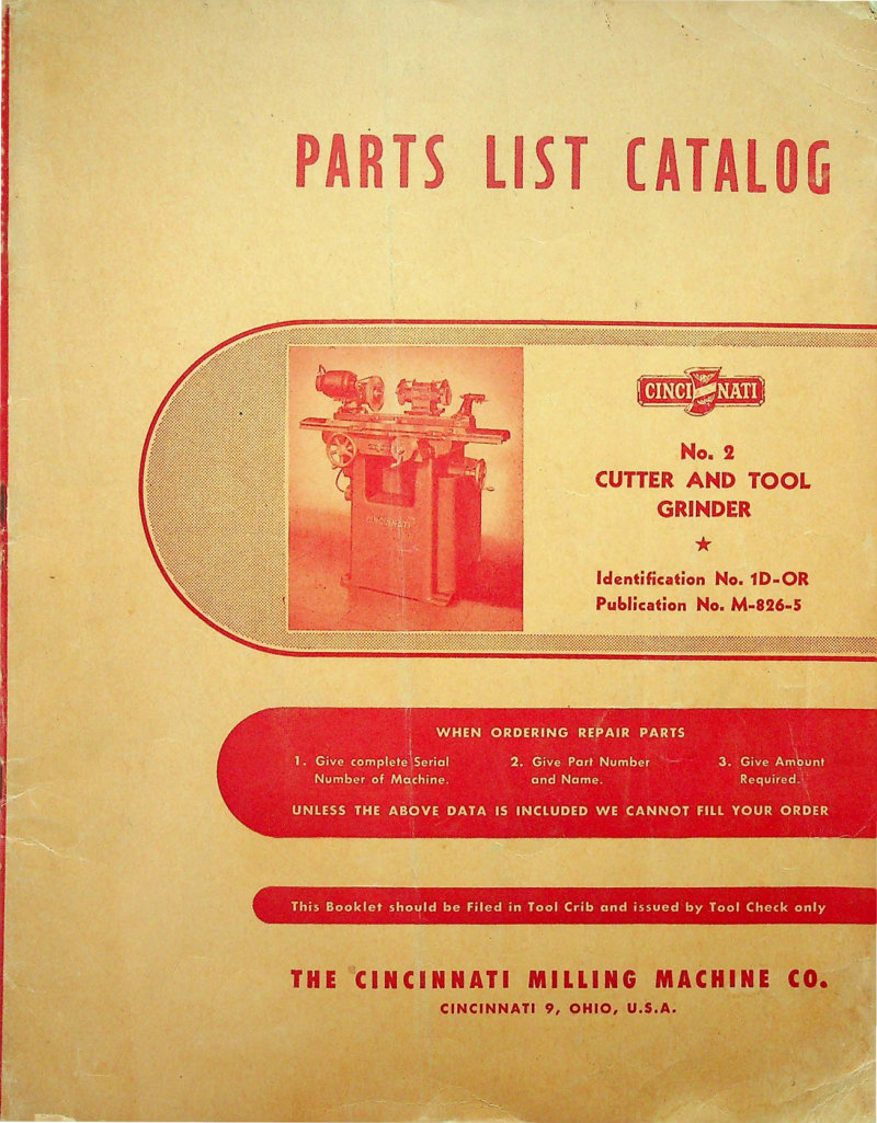
Cincinnati No. 2 Cutter Tool Grinder Parts List
Parts list and catalog for the Cincinnati No. 2 Cutter and Tool Grinder, Model EM. Published by The Cincinnati Milling Machine Co. in Cincinnati, Ohio (Publication No. M-826-5, Identification No. 1D-OR). This parts manual provides detailed ordering information and specifications for replacement components. When placing orders, have the machine's serial number, specific part number, and quantity on hand. Essential reference for technicians maintaining or rebuilding these precision grinding machines. Table of Contents: - SERVICE INSTRUCTIONS - Lubrication Chart, Instructions and Specifications - Nomenclature Chart - Installation Instructions - Leveling - Adjusting the Work Head Spindle Bearings - Adjusting the Belt Tension - Removing the Table and Table Slide - Removing the Cross Feed Screw and Saddle - Removing the Wheel Head and Column - Removing the Sleeve on Column - Removing the Housing - Removing the Spindle Unit - Replacing the Main Driving Belt - Removing the Wheel Head Motor - Removing the Cross Screw Nut - PARTS LIST - Base Parts List - Column and Motor Drive Parts List - Housing and Wheel Head Elevating Parts List - Grinding Wheel Head Parts List - Table and Table Slide Parts List - Saddle Parts List - Tooth Rest Parts List - Work Head Parts List - Cylindrical Grinding Attachment Parts List - Face Mill Grinding Attachment Parts List - Angular Wheel Truing Attachment Parts List - Surface Grinding Attachment Parts List - Internal Grinding Attachment Parts List - Long Reamer Grinding Attachment Parts List - Gear Cutter Sharpening Parts List - Centerless Grinder Work Support Blade Grinding Attachment Parts List - No. 1 Radius Grinding Attachment Parts List - No. 2 Radius Grinding Attachment Parts List - Early Design Radius Grinding Attachment Parts List - Old Style Saddle and Table Parts List - Wet Type Coolant System Attachment - Micrometer Table Leadscrew Attachment - Heavy Duty Tailstock—16" Swing—Attachment - Extended Grinding Wheel Spindles - Standard Grinding Wheels - Cutter Sharpening Arbors - Spindle Extensions - Indexing Attachment - HOW TO ORDER REPAIR PARTS
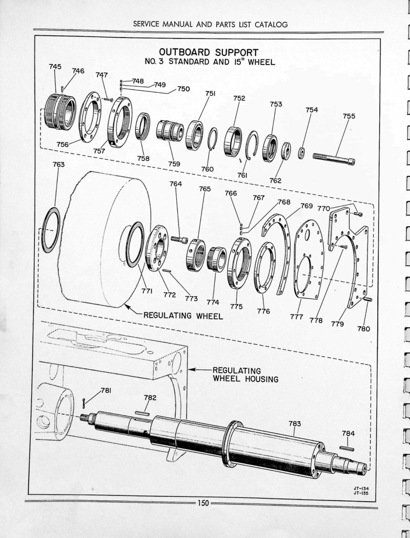
Cincinnati No. 2-3 Centerless Grinding Parts List
Parts list and exploded views for Cincinnati No. 2 and No. 3 centerless grinding machines, Models LO and LL. Contains detailed component identification for outboard support assemblies with standard and 15-inch wheel configurations, spindle components, regulating wheel housings, and associated hardware. Multiple pages show part numbers, assembly diagrams, and parts nomenclature.
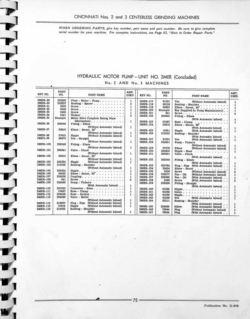
Cincinnati No. 2-3 Centerless Grinding Parts List
Parts list and service documentation for Cincinnati No. 2 and No. 3 centerless grinding machines. Includes detailed parts listings for Hydraulic Motor Pump Unit No. 2MER and Coolant Pump Unit No. 2MP, with part numbers, descriptions, and quantities. Contains schematic drawings of coolant pump and tank assembly with numbered component references. Pages 75-77 of 75 total document.
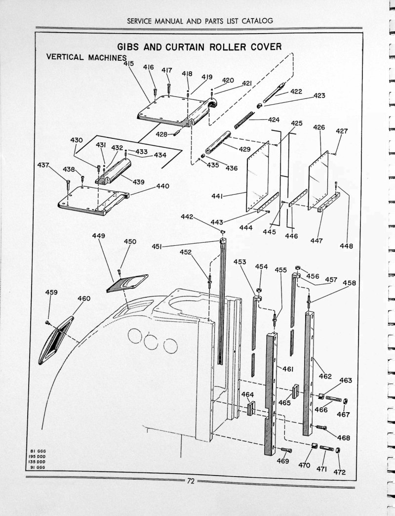
Cincinnati No. 2, 3, 4 Dial Milling Machines Parts List
Parts list and components catalog for Cincinnati dial-type milling machines nos. 2, 3, and 4. This workshop manual provides exploded diagrams for vertical machine assemblies, including gibs, curtain roller cover mechanisms, spring counterbalance systems, and columnar unit subassemblies. Each section details the specific part numbers and required quantities for repair, maintenance, and machine rebuild across all three models. An essential parts reference for technicians servicing these classic Cincinnati machines.
Cincinnati No. 4308 Shear Operation Manual
Operation and Safety Manual for Cincinnati No. 4308 Mechanical Shear — a comprehensive workshop manual covering safe operation and maintenance of this sheet metal shearing machine tool. The manual serves as an essential operator reference that should remain on-site at the shear for quick consultation during daily metalworking tasks. It includes detailed safety guidelines specific to mechanical shearing operations, proper startup and shutdown procedures, and step-by-step instructions for accurate metal cutting. The manual also covers machine adjustments, safe handling practices, and troubleshooting guidance to keep the shear performing reliably. An indispensable resource for operators and maintenance technicians working with Cincinnati sheet metal equipment.
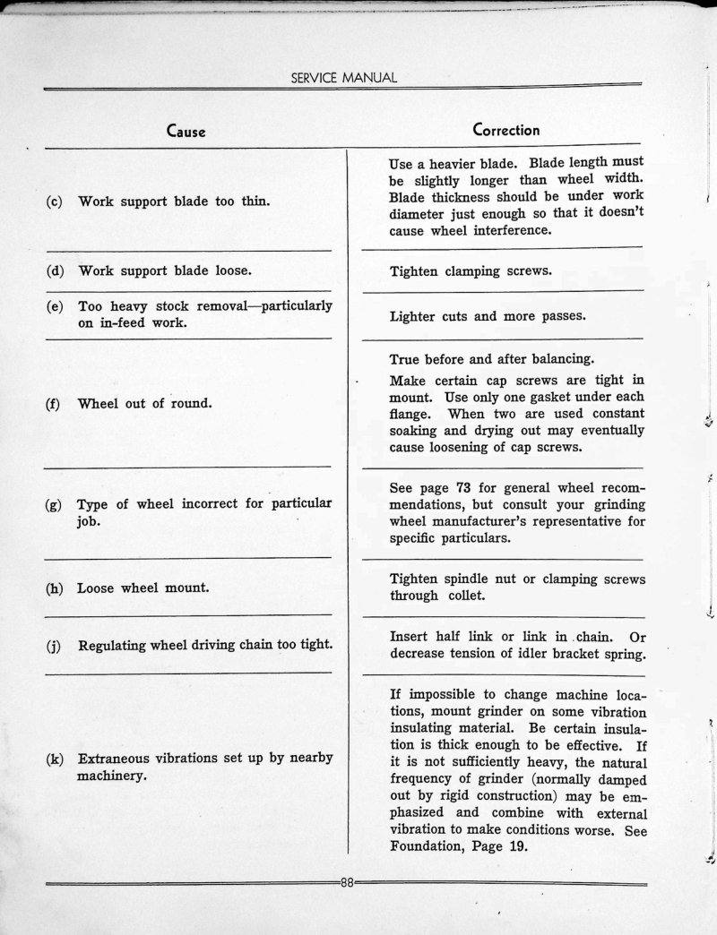
Cincinnati No. 9 Centerless Grinding Machine Service Manual
Service manual for the Cincinnati No. 9 Centerless Grinding Machine, providing comprehensive troubleshooting and correction procedures for this precision grinding equipment. The manual addresses the most common operational issues encountered in centerless grinding, including work support blade wear and damage, wheel condition assessment, spindle bearing performance, diamond holder alignment, work whipping and runout problems, work rest blade positioning, and surface finish defects. Includes detailed cause-and-correction reference tables that guide technicians through systematic problem diagnosis and resolution. Technical figures and guide positioning diagrams (Figures 89A and 90A) illustrate corrections for specific finish conditions such as low ends on chamfered work and low center–high end profile errors. An essential repair and maintenance resource for workshop technicians maintaining Cincinnati centerless grinders.
Cincinnati Nos. 1-2-3-4 Dial Type Milling Service Manual
Service manual and repair parts catalog for Cincinnati Nos. 1, 2, 3 and 4 dial type milling machines, covering both medium speed and high speed production models. Published by The Cincinnati Milling Machine Company, Cincinnati, Ohio. This workshop manual provides complete installation instructions, operational care and maintenance procedures for these precision milling machines, along with detailed repair parts listings to support long-term machine upkeep and restoration work. Document reference M-786-5, 87 pages. Table of Contents: - Lubrication Chart for All Machines - Lubrication Instructions and Specifications - Nomenclature Chart - Installation Instructions - Adjusting the Gibs and Main Driving Clutch - Adjusting the Rapid Traverse Clutch - Removing Leadscrew - Removing Table - Removing Universal Housing - Removing Cross Screw - Removing Cross Screw Nut Bracket - Removing Saddle - Removing Spline Shaft Bracket - Removing Vertical Screw - Removing Change Gear Bracket - Removing Lubricant Pump in Knee - Removing the Knee - Removing Coolant Pump - Removing Pulley Bracket - Removing Feed Box - Removing Gear Shifter Bracket - Removing Hand Feed Worm Box - Removing Power Feed Worm Box - Removing Vertical Spindle - Removing Vertical Head - Removing Horizontal Spindle - Adjustment of Spindle Bearings - Illustration of Front of Column - Removing the Back Gear Shaft - Removing Other Drive Shafts - Removing More Than One Unit - Removing the Overarm - Removing Rear Control Bracket - Setting the Oil Pressure of Pump in Column - Removing the Pressure Pump in Column - Lubrication of Column
Cincinnati Nos. 3, 4, 5 and 6 Milling Machines Operator Manual
Operator's instruction manual for Cincinnati Nos. 3, 4, 5 and 6 High Power and Dual Power Dial Type Milling Machines. Publication No. M-1803, copyright 1951. This 138-page workshop manual covers complete operating and maintenance procedures for these industrial milling machines, including setup, safe operation, and routine upkeep. Essential reference for machine operators and maintenance technicians. Table of Contents: - Principle Machine Specifications - Dimensional Drawings - Standard Equipment - Installation Instructions - Lubrication - Starting the Machine for the First Time - Functional Drawing - Operating Instructions - Automatic Table Cycles - Adjustments - Recommended Cutting Fluid - Cleaning Coolant Reservoir and Strainers - Dividing Head - Wide Range Divider - Milling Cams - Accessories and Attachments—Dividing Head - Accessories and Attachments—Arbors, etc. - How to Store, Handle, and Use Arbors - Accessories and Attachments - Method of Calculating Machining Time - Dividing Head Tables - Ordering Repair Parts - Alphabetical Index
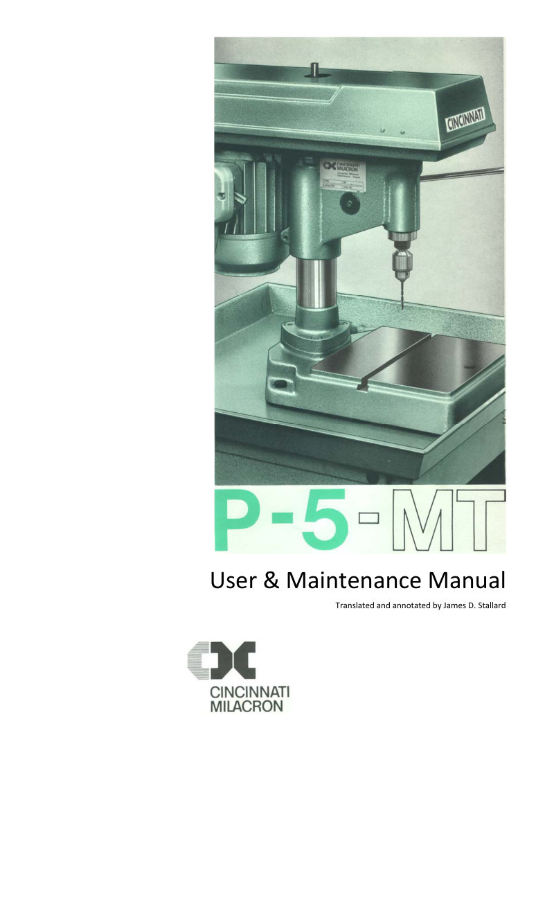
Cincinnati PE5 Bench Drill User & Maintenance
User and maintenance manual for the Cincinnati PE5 benchtop drilling machine. This practical workshop guide covers everything needed to operate and maintain the machine effectively, including technical specifications, step-by-step operational instructions, and detailed adjustment procedures. Comprehensive maintenance guidelines address routine lubrication and cleaning to keep the drill in top condition, along with information on wearing parts and replacement schedules. A complete parts reference section with cutaway diagrams helps you identify and source components. The manual also includes average noise level data for workplace planning. Specifications: maximum drilling capacity of 5 mm in steel, 0.25 kW motor. 15 pages total.
Cincinnati PE5 Drill Press Operation & Maintenance
Operation and maintenance manual for the Cincinnati VR PE 5 drill press. This workshop manual covers complete safety guidelines, performance specifications, and technical data essential for setup and daily operation. Includes detailed installation instructions, step-by-step operation and adjustment procedures, tool guard and hood safety systems, preventive maintenance schedules, and a comprehensive spare parts catalog for ordering replacement components. A practical reference for machine operators and maintenance technicians responsible for reliable press operation.
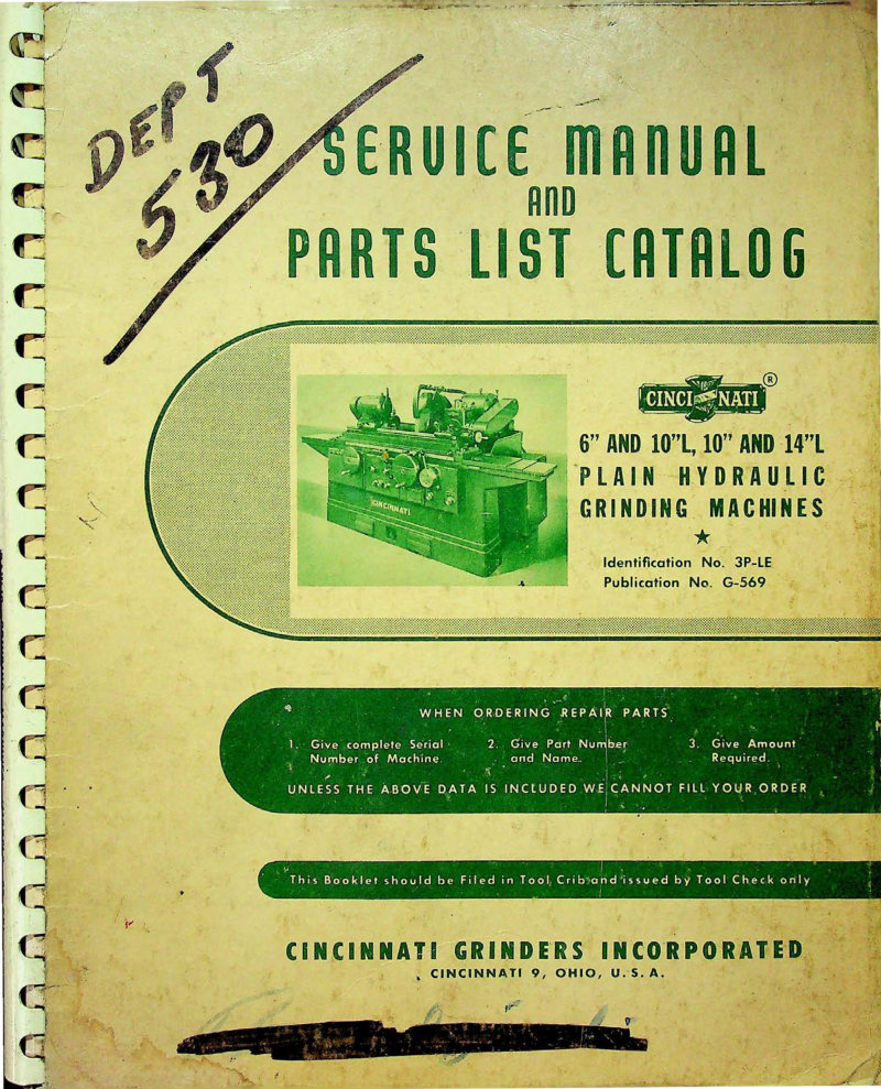
Cincinnati Plain Hydraulic Grinders Service Manual
Service manual and parts catalog for Cincinnati hydraulic surface grinders, covering Models ER (6" and 10") and OE (10"L and 14"L). This workshop manual includes complete adjustment procedures for table operating pistons, servo infeed attachment, footstock spindle, and grinding wheel spindle bearings. Covers configuration and maintenance of the speed safety device, headstock motor drive, spindle drive chain, and V-belt drive system. Details hydraulic oil pressure settings, oil volume delivery to table ways, and electrical pressure switches for hydraulic infeed and spindle circuits. Includes dimensional drawings and floor plan with leveling instructions, cross feed handwheel and pickfeed mechanism specifications, operating control layout, table ways lubrication system schematic, and servo-controlled table circuit explanation. Identification No. 3P-LE, Publication No. G-569. Valid for machines with serial numbers beginning with "3P" or "6P". Original 1947 publication. Table of Contents: - # INDEX - ADJUSTMENTS - To Adjust Alignment of Table Operating Pistons - Automatic and Hand Servo Infeed Attachment - Footstock Spindle - Grinding Wheel Spindle Bearings - Grinding Wheel Spindle Thrust Bearing - Grinding Wheel Spindle V-Belt Drive - Grinding Wheel Speed Safety Device - Headstock Motor Drive V-Belts - Headstock Motor Unibrace—6" and 10" L Grinders only - Headstock Spindle Drive Chain—6" and 10" L Grinders - Headstock Spindle Drive V-Belts—10" and 14" L Grinders - Hydraulic Oil Pressure - Volume of Oil to Table Ways - Setting of Hydraulic Infeed and Spindle Oil Electrical Pressure Switches - CONVERSION CHART (Inches to Millimeters) - DIAGRAMS AND ILLUSTRATIONS - 6" and 10" L Plain Hydraulic Grinders - Dimensional Drawing - Left Rear View - Right Front View - Right Rear View - 10" and 14" L Plain Hydraulic Grinders - Dimensional Drawing - Floor Plan and Leveling Instructions for 10" and 14" L x 72" Grinder - Floor Plan and Leveling Instructions for 10" and 14" L x 96" Grinders - Left Front View - Left Rear View - Right Rear View - 6" and 10" L, 10" and 14" L Plain Hydraulic Grinders - Cross Feed Handwheel and Pickfeed Mechanism - Operating Control Knobs and Lever - Schematic Layout of Table Ways Lubrication System - Hydraulic Circuits (Insert at back of book) - Table Circuit with Servo Control - Explanation
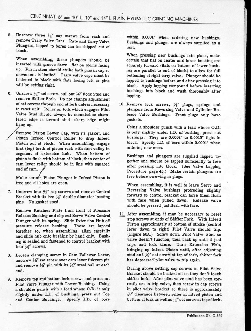
Cincinnati Plain Hydraulic Grinding Service Manual
Service manual pages 59-61 for Cincinnati 6 inch, 10 inch, 10 inch L, and 14 inch L plain hydraulic grinding machines. This maintenance section covers systematic disassembly and repair procedures for footstock assemblies, wheelhead components, spindle units, and valve systems. Detailed step-by-step instructions walk you through removal and dismantling of each major assembly, with critical technical specifications for clearances and part dimensions needed to reassemble the machines correctly. Essential reference for technicians and operators maintaining these industrial grinders.
Cincinnati Plain Vercipower Service Manual
Service manual and parts list catalog for Cincinnati Plain Vercipower milling machines equipped with Telematic Control or Auto Cycle Model DK (machines shipped after 1965). This comprehensive repair guide and workshop reference covers functional and dimensional diagrams, machine specifications, conversion charts, and installation procedures. Detailed maintenance and lubrication instructions include diagrams and charts to ensure proper operation. Adjustment procedures address gibs, motor belt tension, bevel gear and clutch shafts, backlash eliminator, crosshead screw bearing, table load screw bearing, front elevating screw bearing, vertical screw brake, spindle bearings, hydraulic pressure settings, arbor support bushings, and dynamoise overjam compensation. Features a key number index and complete ordering information for replacement parts, making this an essential troubleshooting and maintenance resource for owners and technicians. Table of Contents: - FUNCTIONAL DIAGRAM - DIMENSIONAL DIAGRAM - MACHINE SPECIFICATIONS - CONVERSION CHART - INSTALLATION INSTRUCTIONS - General - Location - Foundation - Cleaning - Bolting the Machine to the Foundation - Leveling the Machine - Initial Lubrication - Assemble Table to Machine - LUBRICATION INSTRUCTIONS - General - Automatic Lubrication - Scavenger Pumps - Filters - LUBRICATION DIAGRAM - LUBRICATION CHART - ADJUSTMENTS - Adjusting the Gibs - Adjusting the Motor Belt Tension - To Adjust Bevel Gear and Clutch Shafts, Brake and Clutches - To Adjust Backlash Eliminator - To Adjust Crossfeed Screw Bearing - To Adjust Table Lead Screw Bearing - To Adjust Front Elevating Screw Bearing - To Adjust Vertical Screw Brake - To Adjust Spindle Bearings - Hydraulic Pressure Adjustments - To Adjust Arbor Support Bushings - To Adjust Dampoise Overarm - HOW TO ORDER REPAIR PARTS - KEY NUMBER INDEX
Cincinnati Press Brake 130 Series Operator's Manual
Operator's manual for Cincinnati Press Brake, 130 Series and smaller models. Published by The Cincinnati Shaper Company, Cincinnati, Ohio. This is a temporary manual serving until a new manual is prepared. Covers care and operation of the press brake.
Cincinnati Press Brake Operator's Manual
Operator's manual for Cincinnati press brakes, 13 series and smaller models. This comprehensive workshop guide covers unloading procedures, proper lifting techniques, foundation installation requirements, and day-to-day operation of these industrial machines. Includes detailed safety instructions and professional rigging guidelines for machinery movers handling equipment setup and relocation. References a 9 x 10' Cincinnati press brake model 3 with serial number 10662. Essential reference for machine operators and maintenance technicians working with Cincinnati press brake systems.
Cincinnati Press Brakes Operator's Manual
Operator's manual for Cincinnati press brakes manufactured by The Cincinnati Shaper Company of Cincinnati, Ohio. Covers the 13 Series and smaller models. This workshop manual provides comprehensive guidance on safe operation, routine maintenance, and proper care of Cincinnati press brake equipment, serving as an essential reference for machine operators and maintenance personnel. Table of Contents: - UNLOADING - LIFTING - FOUNDATION
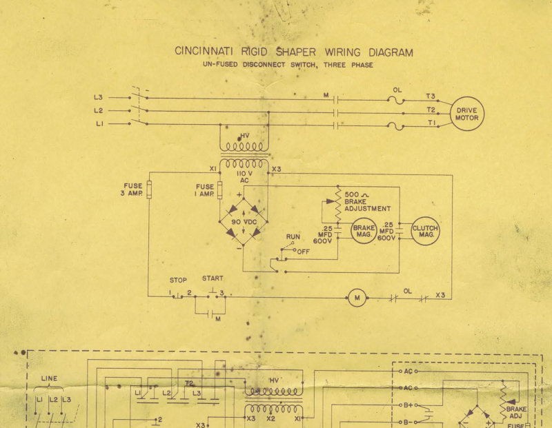
Cincinnati Rigid 16 Inch Shaper Schematic
Electrical wiring schematic for the Cincinnati Rigid 16 Inch Shaper featuring an unfused disconnect switch rated for three-phase operation. The diagram maps the complete control and power distribution system, including a 110V AC transformer, 90 VDC power supply, brake adjustment circuit rated at 500A, and the rectifier unit that converts AC to DC. Also detailed are the clutch and brake control capacitors (25 MFD 600V), the electric brake and clutch assemblies, and the drive motor control circuit with integrated stop and start switching. This service schematic is essential for troubleshooting electrical faults, verifying circuit continuity, and performing maintenance on the shaper's electrical systems. Document number 201825.
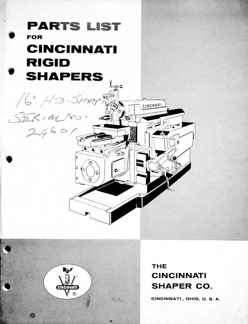
Cincinnati Rigid Shapers Parts List
Parts list for Cincinnati Rigid Shapers covering identification and assembly with illustrated diagrams for both Universal Table and Plain Table setups. Organized into 37 part groups spanning the complete machine: Head, Ram, Column, Rocker Arm, Crank Gear, Transmission, Clutch & Brake, Power Rapid Traverse, Feed Mechanism, Feed Box, Speed Change, Power Vertical Traverse, Rail, tables, Oiling system, Motor Mount, Electrical Box, Wrenches, Tool Lifter, Power Down Feed to Head, and Vises. Accurate parts matching requires serial number, stroke size, and duty size when ordering. Essential reference for technicians sourcing replacement components or performing maintenance on Cincinnati Rigid Shaper equipment.
Cincinnati Shaper Operation and Maintenance
Operation and Maintenance Manual for Cincinnati Shaper machines. This workshop manual provides detailed identification diagrams with front and rear views, labeling 30 key components including the tool slide, ram, apron, cross feed mechanisms, and control elements essential to understanding machine layout and function. Covers operational procedures, setup guidance, and maintenance protocols for keeping this precision shaping tool in reliable working condition. Originally published by The Cincinnati Shaper Company, Cincinnati, Ohio. A practical reference for operators and technicians responsible for Cincinnati Shaper equipment.
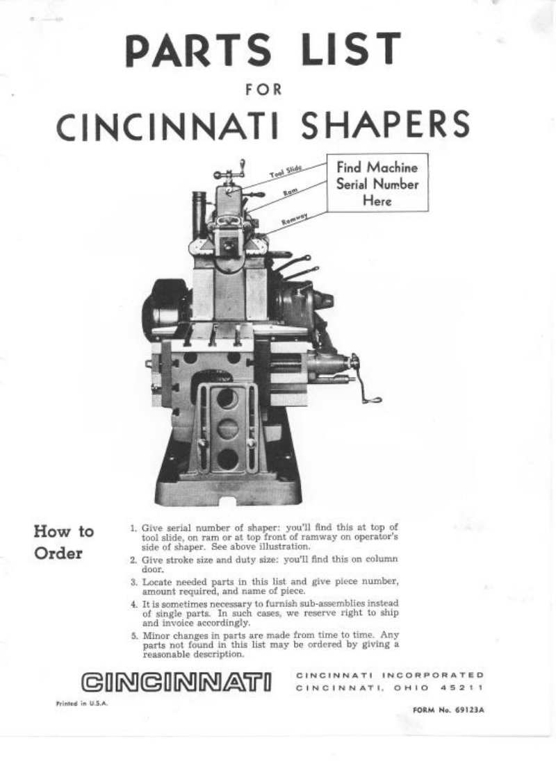
Cincinnati Shaper Parts List
Parts list for Cincinnati Shaper machines with comprehensive indexed reference groups covering all major assemblies: Head Group, Feed Box Group, Feed Mechanism Group, Drive Group, Rocker Arm Group, Rapid Traverse Group, Crank Gear Group, Rail Group, Speed Change Group, Clutch Shifter Group, Column Group, Ram Group, Motor Drive Group, Oiling Group, Power Down Feed to Head Group, Plain Table, Universal Table, Single Screw Vise, and Double Screw Vise. Essential for ordering replacement parts and identifying components by assembly. Instructions reference the machine's serial number, stroke size, and duty size as marked on the equipment.
Cincinnati Shapers Operator's Manual
Operator's manual for Cincinnati Shapers machine tools. Covers installation on foundation, leveling procedures, and pulley speeds for utility, standard, and heavy models ranging from 20 to 56 inches (500 RPM for utility and heavy variants, 5.50 RPM for standard and heavy duty). Detailed guidance on drive system operation, automatic oiling of the main reservoir, and lubrication distribution to the ram bearing and rocker arm. Includes feed mechanism control, table adjustment, stroke settings, and comprehensive maintenance procedures. Features in-depth sections on shaper care, gib adjustments, clutch mechanisms, tool chatter prevention, and speed control. Technical diagrams illustrate foundation layout, drive system components, and adjustment details throughout. A practical reference for shaper operation and upkeep on the shop floor.
Cincinnati Shapers Operator's Manual
Operator's manual for Cincinnati Shapers machines, covering installation, operation, and maintenance of these industrial shapers. The manual details foundation preparation and leveling procedures essential for proper machine setup. Operating sections explain drive system mechanics, lubrication schedules and oiling points, clutch and gib adjustment techniques, strategies to eliminate tool chatter, and routine maintenance practices. Technical diagrams illustrate machine layout, drive mechanism operation, ram positioning control, table feed adjustments, and gib alignment — making this an indispensable workshop reference for operators responsible for day-to-day shaper maintenance and troubleshooting.
Cincinnati Shapers Operator's Manual
Operator's manual for Cincinnati Shaper machine tools, essential reference for safe setup and daily operation of these precision metalworking machines. Covers complete installation procedures including foundation design and specifications for both 24" Standard and 24" Heavy Duty models, with detailed guidance on unpacking, lifting using rope slings, and initial site preparation. Explains proper handling of ram bearings and head assembly components to maintain accuracy over time. Details the lubrication schedule and protective maintenance procedures needed to preserve precision surfaces and ensure reliable performance. This workshop manual provides the practical knowledge required to get your Cincinnati Shaper operational and keep it running smoothly through routine care and correct operating practices.
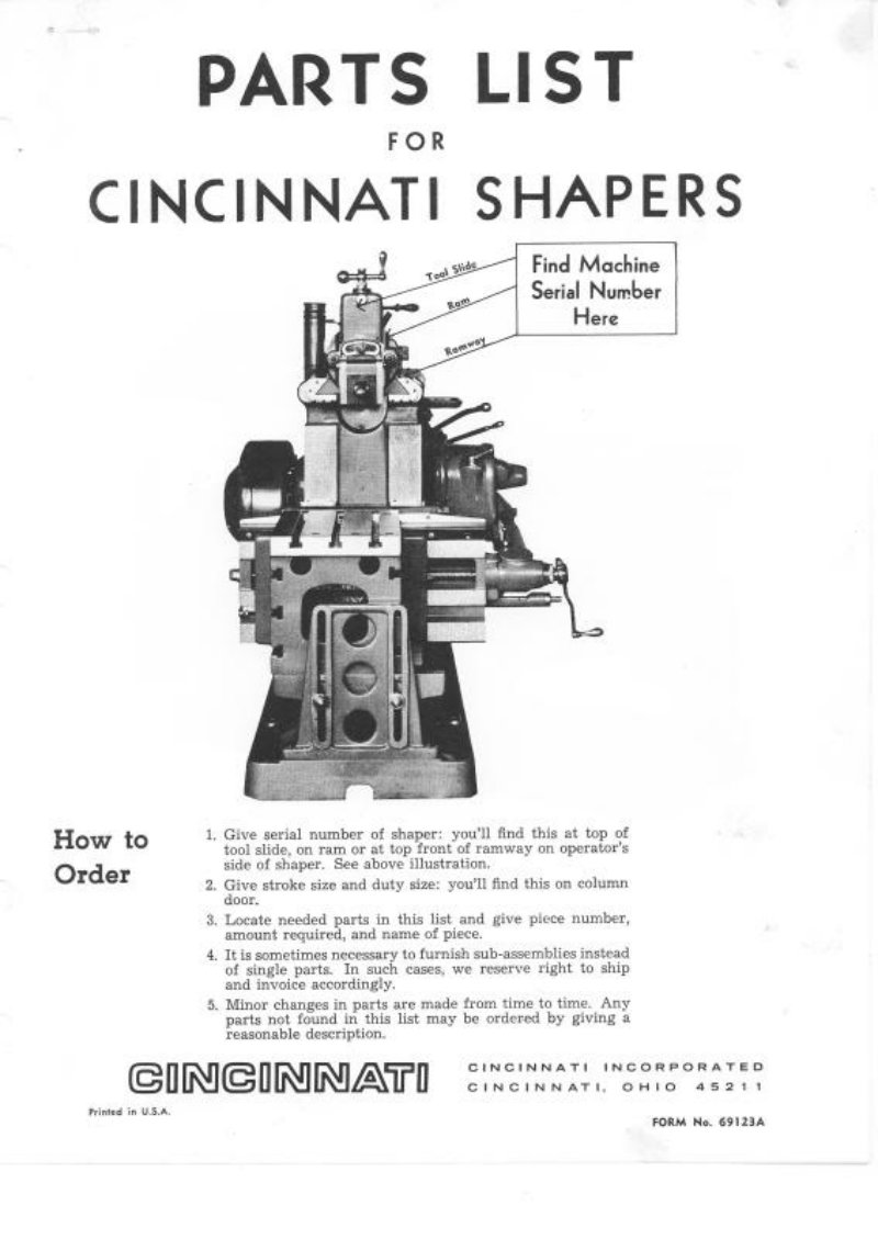
Cincinnati Shapers Parts List
Comprehensive parts list for Cincinnati shaper machine tools, essential for identifying and ordering replacement components. The catalog systematically indexes component groups with page cross-references for quick navigation: Crank Gear Group, Clutch Shifter Group, Column Group, Drive Group, Feed Mechanism Group, Feed Box Group, Head Group, Motor Drive Group, Oiling Group, Power Down Feed to Head Group, Rocker Arm Group, Rapid Traverse Group, Rail Group, Ram Group, and Speed Change Group. Also covers table options (plain and universal designs) and vise selections (single and double screw configurations). Detailed ordering instructions specify required information including serial number, stroke size, duty classification, and individual piece numbers to ensure accurate part matching. Direct contact information provided for Cincinnati Incorporated's service department in Cincinnati, Ohio, facilitating parts procurement and technical support for machine maintenance and repair.
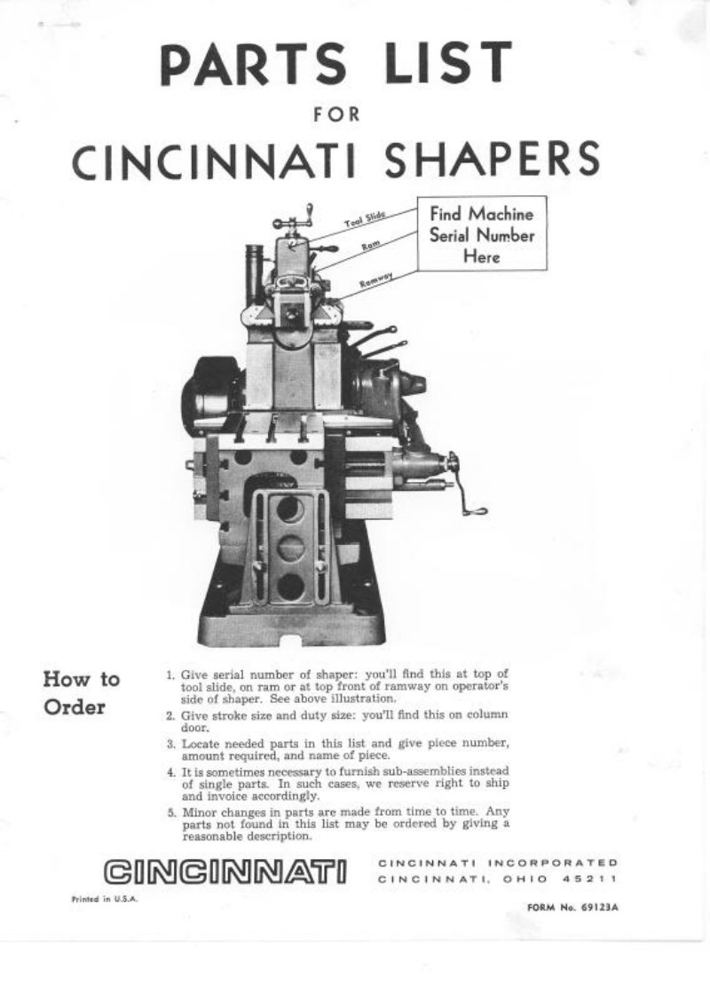
Cincinnati Shapers Parts List
Cincinnati Shapers parts list from The Cincinnati Shaper Co., Cincinnati 25, Ohio. This parts catalog provides ordering instructions, machine serial number location reference, and a detailed component index organized by functional groups: head assembly, feed mechanism, feed box, drive train, rocker arm, crank gear, clutch shifter, rapid traverse, rail system, speed change, ram, table, vise, oiling system, power down feed to head, motor drive, and column. Pages 1–3 visible with complete index and service information. Table of Contents: - Crank Gear Group - Clutch Shifter Group - Column Group - Drive Group - Feed Mechanism Group - Feed Box Group - Head Group - How To Order - Motor Drive Group - Oiling Group - Power Down Feed to Head Group - Rocker Arm Group - Rapid Traverse Group - Rail Group - Ram Group - Speed Change Group - Table, Plain - Table, Universal - Vise, Double Screw - Vise, Single Screw
Cincinnati Shears 4308R Operator's Manual
Operator's manual for Cincinnati Shears Model 4308R (Serial #14812), a heavy-duty metal shearing machine manufactured by The Cincinnati Shaper Company, Cincinnati, Ohio. This workshop manual provides complete operating and maintenance guidance for safe and efficient use of the shearing machine, covering setup, operational procedures, and equipment care.

Cincinnati Shears Installation Manual
Installation manual for Cincinnati Shears machine tools covering the complete setup process from equipment delivery through final positioning. Details unloading procedures, foundation requirements and site preparation, skid removal techniques, and safe lifting methods using crane equipment. Provides step-by-step leveling instructions employing precision levels and steel shims to achieve proper machine alignment. Procedures apply to both 62 and 100 series shears equipped with jack lugs. Essential reference for installing and commissioning these industrial cutting machines.
Cincinnati Shears Operation Manual
Operation and maintenance manual for Cincinnati Shears model 1812, manufactured by The Cincinnati Shaper Company in Cincinnati, Ohio. This workshop manual provides essential operational procedures and maintenance guidance for the shear equipment, covering daily operation, routine upkeep, and troubleshooting. Documentation confirms copies held by Allison Division of General Motors (serial #25354) and USAF (reference 463214, Mill Wright Shop), reflecting the equipment's established use in industrial and military machine shops. Table of Contents: - Identification - Installation - Lubrication - Operation - Power operated back guage - Ram adjustment - Changing and setting knives - Front gauging - Maintenance - Accurate performance - Drive - Clutch - Friction brake - Clutch & Brake timing - Holddowns - Counterbalance - Ordering repair parts
Cincinnati Shears Operator's Manual
Operator's manual for Cincinnati Shears, a heavy-duty metal shearing machine tool manufactured by The Cincinnati Shaper Company of Cincinnati, Ohio. This workshop manual provides comprehensive guidance on safe operation, maintenance, and upkeep of the shear. The document includes handwritten service notes identifying the specific machine as serial number 21724, model 4312 Shear with 1/4-inch capacity and Standard Steel construction—details essential for matching this manual to your exact equipment. An invaluable reference for machine operators, maintenance technicians, and shop floor supervisors.
Cincinnati Shears Operator's Manual
Operator's manual for Cincinnati Shears metal shearing machine tool. This comprehensive workshop manual covers installation procedures including proper unloading techniques, lifting and crane rigging diagrams for safe equipment positioning, and detailed foundation requirements to ensure stable setup. Essential reference for anyone operating or maintaining this heavy-duty shear press.
Cincinnati Shears Series 14-18 Operator's Manual
Operator's manual for Cincinnati Shears machine tool for shearing metal. Covers unloading and installation instructions, lifting procedures with crane handling guidance, and foundation requirements. Includes lifting hitch diagrams and photographs. Published by The Cincinnati Shaper Company, Cincinnati 25, Ohio.
Cincinnati Slotting Attachments Service Manual
Service manual and parts list catalog for Cincinnati slotting attachments with serial numbers beginning with AT. This comprehensive workshop manual includes dimensional drawings, functional diagrams, and detailed mounting instructions for installing the attachment on your machine. You'll find complete lubrication specifications, setup and adjustment procedures to ensure proper operation, along with systematic dismantling instructions for maintenance and repair work. The parts list with explanations helps you identify and order replacement components, and a directory of field offices provides direct access to Cincinnati service support. Originally published in 1944 by Cincinnati Milling Machine Co., this document remains an essential reference for anyone maintaining or troubleshooting these precision slotting attachments.
Cincinnati Special Blade Grinding Machine Operation Manual
Operation manual for the Cincinnati Special Blade Grinding Machine, fixture type, serial number 3590MC05U-0003. Published as revision G-853-B on December 19, 1969. This comprehensive workshop manual documents the electrical operator controls for control station number 1, providing detailed guidance on wheelhead retraction, multi-stage feed systems (fast, fine, and micro feed modes), tarry function, gage advance mechanisms, master start and stop controls, hydraulic and way filtration, spindle filtration, gage selection, power unit operation, cross-slide and sub-slide position controls, headstock speed regulation and jog functions, gage advance and retract operations, and coolant system management. An essential reference for operators and technicians maintaining and running Cincinnati precision grinding equipment.
Cincinnati Toolmaster Milling Machines Owner's Manual
Operator's instruction book for Cincinnati Toolmaster milling machines. Covers models 1A, 1B, and 1C. Includes figures showing Style 1-A with manual feed to quill and Style 1-B with power feed to quill. Principal machine specifications table detailing range, table dimensions, spindle nose type, spindle speeds, drive options, floor space, and shipping data. Publication No. M-1941, copyright 1954.
Cincinnati Toolmaster Service Manual and Parts List
Comprehensive service manual and parts list for Cincinnati Toolmaster milling machines covering models 1B, 1C, 1D, 1E, and HV. Originally published by The Cincinnati Milling Machine Co., Milling Machine Division in Cincinnati, Ohio. This workshop manual provides everything needed for maintenance, repair, and overhaul of these industrial milling machines. Includes detailed dimensional drawings, step-by-step disassembly and reassembly procedures, functional schematics, and installation guidance. Covers lubrication specifications, drive belt adjustment, gibs, headstock clutch operation, backlash eliminator calibration, and arbor support bushing configuration. Features exploded parts diagrams and complete parts ordering information for sourcing genuine replacement components. An essential reference for machine shop technicians, maintenance personnel, and operators responsible for keeping Toolmaster mills in proper working condition. Table of Contents: - ADJUSTMENTS - To Adjust Arbor Support Bushing - Backlash Eliminator - Drive Belts: Style 1-B - Drive Belt: Style 1-E - Gibs - Quill Powerfeed Clutch: Style 1-B - Shaping Attachment Drive Belt - Shaping Attachment Gib - CONVERSION CHART (Inches to M/M) - DIMENSIONAL DRAWINGS - DISASSEMBLY INSTRUCTIONS - To Remove V-Belt Housing: Style 1-B - To Remove V-Belt Housing: Style 1-D - To Remove V-Belt Housing: Style 1-E - Splined Spindle Sleeve: Style 1-B - Drive Spindle Assembly: Style 1-B - Drive Spindle Assembly: Styles 1-b, 1-E - Spindle Housing with Spindle: Style 1-B - Spindle Housing with Spindle: Styles 1-b, 1-E - Spiral Gear Shaft: Style 1-B - Transmission Shaft: Style 1-B - Speed Change Assembly: Style 1-D - and Dismantle Powerfeed Housing: Styles 1-D, 1-E - Overarm and Turret: Styles 1-B, 1-D, 1-E - Overarm (Heavy Base): Styles 1-C, 1-F - and Dismantle Overarm Gear Housing: Styles 1-C, 1-V - Spindle Housing and Drive — Without Hand Feed: Styles 1-C, 1-V - Spindle Housing and Drive — With Hand Feed: Styles 1-C, 1-V - and Dismantle Intermediate Swivel Housing: Styles 1-C, 1-V - Table - Table Leadscrew - Table Powerfeed Housing - To Dismantle Table Powerfeed Housing - To Remove Standard Saddle - To Remove Crossfeed Screw - and Dismantle Saddle When Table Is Equipped With Powerfeed - To Remove Saddle Powerfeed Housing - Elevating Crank Shaft - Elevating Screw and Pedestal - Knee - To Dismantle Shaping Attachment - To Install Table or Saddle Powerfeed Motor - FUNCTIONAL DIAGRAMS - INSTALLATION INSTRUCTIONS - LUBRICATION DIAGRAM AND SPECIFICATIONS - ORDERING REPLACEMENT GIBS - REPAIR PARTS - KEY NUMBER INDEX - COLUMN (Unit 6JC) - COOLANT PUMP AND PIPING (Unit 6JP) - HEAVY DUTY HEAD AND OVERARM (Unit 6JIS) - HIGH SPEED HEAD AND OVERARM (Unit 6JIR) - HOW TO ORDER REPAIR PARTS - INDEX HEAD AND TAILSTOCK (Unit 6JKA) - KNEE (Unit 6JO) - MACHINE INSTRUCTION PLATES - OPTIONAL HANDHELD EQUIPMENT (6JKT) - PLAIN, SWIVEL AND UNIVERSAL VISES (Unit 6JKA) - PRECISION MEASURING EQUIPMENT (Unit 6JLI) - SADDLE-TABLE (Unit 6JI) - SHAPING ATTACHMENT (Unit 6JHF) - VARI-SPEED HEAD AND OVERARM (Unit 6JKV)
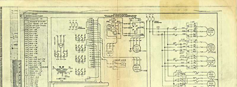
Cincinnati Toolmaster Wiring Schematic K-148187
Complete electrical wiring schematic documentation for the Cincinnati Toolmaster machine model K-148187. This technical resource covers the interconnection table, main power distribution wiring diagram, control circuitry layout, motor connection specifications, and detailed component identification with terminal designations and signal paths. Essential reference material for technicians performing maintenance, troubleshooting, or electrical repair work on this industrial machine.
Cincinnati Tray-Top LE Service Manual
Service manual and parts list for Cincinnati Tray-Top Model LE engine and toolroom lathes available in 10", 12.5", 15", and 18" swing sizes, plus fixed gap bed variants in 15" and 18". Covers initial setup and commissioning, operation fundamentals, routine maintenance schedules, troubleshooting procedures, and detailed repair guidance for both mechanical and electrical systems. This workshop manual serves as the essential reference for owners and technicians performing service work on these precision machine tools.
Cincinnati Universal Dividing Heads Parts List
Parts list catalog for Cincinnati universal dividing heads and accessories, No. 50 Series Spindle Nose. Contains dimensional drawings, standard and wide range dividing head plates, lubrication instructions, mounting attachment details, enclosed driving mechanism information, lead attachment specifications, dividing head setup for milling spirals, worm adjustment procedures, and comprehensive parts listing for 10", 12" and 14" dividing heads with driving mechanisms (Units CUA, CVA, CWA). Serial numbers begin with C, V or W. Publication M-2364-1. Table of Contents: - Dimensional Drawing – Dividing Head - Plate – Standard and Wide Range Universal Dividing Head - Lubrication Instructions and Specifications – Dividing Head - Mounting Attachment on Machine – Dividing Head - Plate – Enclosed Driving Mechanism - Plate – Long and Short Lead Attachment - Plate – Dividing Head Set Up with Enclosed Driving Mechanism for Milling Spirals - Adjusting the Dividing Head Worm - How to Order Repair Parts - 10", 12" and 14" Dividing Heads and Accessories (Unit CUA) - Driving Mechanism for 10", 12" and 14" Universal Dividing Heads (Unit CVA) - Driving Mechanism for 10", 12" and 14" Universal Dividing Heads (Unit CWA)
Cincinnati Vercipower Milling Machines Parts List
Parts list and technical reference for Cincinnati Vertical Vercipower Milling Machines covering models 300, 400, 500, 600, and 700 (Model DH), applicable to units with serial numbers beginning 9J. This comprehensive workshop manual includes functional and identification diagrams, dimensional drawings, and complete breakdown of all major assemblies: spindle carrier, pulley bracket, motor drive, headstock, saddle-table, front bracket, feed box, bed, and coolant pump. Features detailed lubrication instructions, key number index for rapid component identification, automatic table cycle diagrams, hydraulic circuit schematic, and electrical controls location guide. An essential reference for technicians performing maintenance, repair, or parts ordering on these classic Cincinnati milling machines. Table of Contents: - Functional Diagram - Identification Diagrams - Dimensional Drawing - Lubrication Instructions - How to Order Repair Parts - Key Number Index - Spindle Carrier and Parts List - Pulley Bracket and Parts List - Motor Drive and Parts List - Headstock and Parts List - Saddle-Table and Parts List - Front Bracket and Parts List - Feed Box and Parts List - Bed and Parts List - Coolant Pump and Parts List - Instruction Plates and Parts List - Ordering Replacement Gibs - Automatic Table Cycles - Hydraulic Circuit - Location of Electrical Controls
Cinel 60 Milling Machine Operator's Manual
Operator's instruction manual for Cincinnati Cinel 60 plain and universal milling machines. Publication No. M-2439. This workshop manual covers setup, operation, and proper use of both machine configurations. Includes patent notices and serial number reference information essential for identification and parts ordering. A practical guide for machinists and machine operators working with Cincinnati's Cinel 60 series on the shop floor.
Cinel 60 Milling Machine Service Manual
Service manual and parts list for the Cincinnati Cinel 60 Model DH milling machine, applicable to machines with serial numbers beginning with 5J. This workshop manual covers adjustment procedures, dimensional and functional diagrams, lubrication schematics, and repair parts location guides essential for maintaining and servicing this industrial milling machine. Detailed dismantling instructions address key mechanical assemblies including arbor support bushings, backlash eliminator, cross screw bearings, drying clutch, dynapoise overarm, gibs, hydraulic pressure systems, main drive belts, spindle bearings, table lead screw bearings, feed mechanisms, control shafts, clutches, gears, elevating screws, knee assemblies, drive brackets, traverse clutches, control idler gears, saddle iron, safety guard, selector valve, shifter bracket, spline shaft, and drive shafts. Includes installation diagrams and location information for all electrical components. Published by Cincinnati Milling Machine Company, Cincinnati, Ohio 45209.
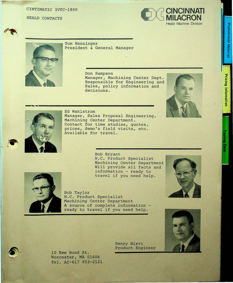
Cintimatic 3VTC-1800 Machining Center - Technical Data
Price list and technical data sheet for the Cintimatic 3VTC-1800, a three-axis CNC machining center built by Cincinnati Milacron. Original documentation dated January 2, 1973, lists the machine at $152,975 and provides comprehensive specifications for the standard configuration. The vertical spindle delivers 15 HP with Acramatic 5 numerical control, backed by a 24-station automatic tool changer drum for rapid tool access during production runs. The sliding head mechanism offers 30 inches of Z-axis travel and handles a 3-ton work load across the 30 by 72 inch worktable, which supports up to 6000 pounds. DC electric servo drives on all three axes ensure precision positioning, while the integrated automatic lubrication system reduces manual maintenance. Includes manufacturer contact details for Cincinnati Milacron's Head Machine Division in Worcester, Massachusetts.
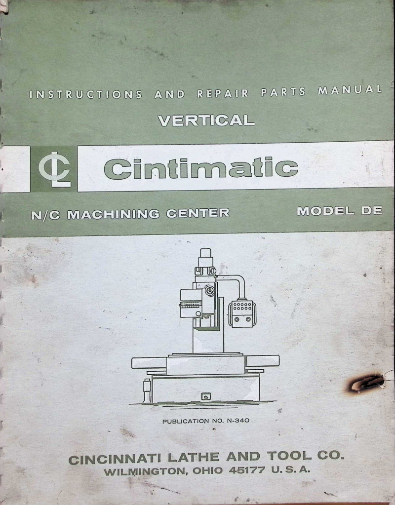
Cintimatic Model DE Vertical Machining Center Manual
Technical service manual for the Cincinnati Cintimatic Model DE vertical N/C machining center (Publication N-340). This workshop manual provides complete guidance on installation, lubrication, operation, adjustment, and maintenance of the machine. Covers all essential procedures a shop technician needs to keep the Cintimatic DE running reliably, including setup specifications, daily maintenance routines, troubleshooting of common issues, and detailed repair information. Also includes warranty terms and design specifications.
Cintimill 203-205 Model DH Service Manual
Complete service manual for the Cincinnati Cintimill 203-205 Model DH milling machine, published by Cincinnati Lathe and Tool Co. in Cincinnati, Ohio. Publication number C-450-1. This workshop manual combines detailed instruction documentation with a comprehensive parts list, essential for technicians performing maintenance, repair, and rebuilding work on this classic industrial milling machine. Includes foreword and full warranty coverage details outlining defect protection and authorized parts replacement procedures.
Cinturn 1208/1210/1212 Diagnostics Manual
Diagnostics manual for Cincinnati Milacron Cinturn turning centers—models 1208, 1210, and 1212 equipped with the Acramatic 850TC control system. Publication no. 3-TC-84351. This 118-page workshop manual covers comprehensive troubleshooting and diagnostic procedures essential for maintaining and servicing these CNC lathes. Technicians will find step-by-step guidance for identifying and resolving operational faults, making this an indispensable reference for repair and maintenance work on Cinturn machine tools. Table of Contents: - # Table of Contents Entries - Based on the document shown, there is no actual table of contents list visible on this page. This page is titled "HOW TO USE THIS MANUAL" and contains instructional text about how to navigate the manual's organization, along with a diagram showing the INDEX TAB, FIGURE NUMBER AND TITLE, PUB NUMBER, and PAGE NUMBER. - No specific chapter or section titles are listed on this page.

Cinturn 8C CNC Chucking Center Maintenance Manual
Maintenance manual for the Sealed Power Cinturn 8C CNC Chucking Center. This workshop manual provides comprehensive lubrication schedules with detailed specifications for all major machine components, including counter-balance cylinder, hydraulic reservoir, spindle motor, auto-lube system, power chuck, turret, tailstock variants, auto steady rest, and chip conveyor. The manual specifies exact lubrication types (P-64, P-38, P-50, P-72, Molykote BR2 Plus, Mobilgrease #28) and application intervals ranging from 6.5 to 2000+ operating hours, along with step-by-step instructions for greasing procedures, oil level checks, and bearing repacking. An essential service reference for operators and maintenance technicians responsible for keeping the Cinturn 8C running at peak performance and extending equipment life.
Cinturn DC Spindle Drive Service Manual
Service manual for DC spindle drive units on Cincinnati Milacron Cinturn Series 1208, 1210, and 1212 turning centers equipped with Acramatic 850TC controls. Covers Reliance MaxPak Plus V*S spindle drive systems with 20hp or 30hp DC motors. This workshop manual includes adjustment procedures, installation checks, and tuning instructions essential for maintaining and troubleshooting spindle drive assemblies on Cinturn turning centers. Designed for qualified service personnel.
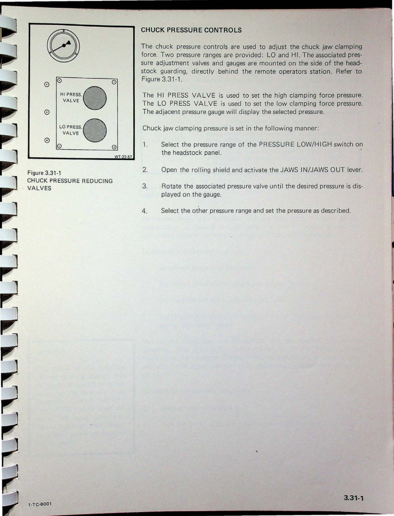
Cinturn Series C MA Service Manual - Part 2
Part 2 of the Cinturn Series C Model MA turning center service manual covers essential operating procedures and control system maintenance for this CNC lathe. This section details chuck pressure management, including both high and low pressure valve operation and gauge calibration, along with the safety override mechanism for electrical cabinet door interlocks. Technicians will find step-by-step guidance on control adjustments and related operating devices across pages 3.31-1 through 3.32-1. An indispensable workshop reference for anyone servicing or troubleshooting these Cincinnati turning centers. Table of Contents: - TOOLING - OD TOOLING - OD COMMON TOOL POINT
Cinturn Series C Turning Centers Operating Manual
Operating manual for Cincinnati Milacron Cinturn Series C turning center model MA with Acramatic 900TC control system. Publication 1-TC-8001. This workshop manual provides detailed guidance on machine setup, operation modes, control panel functions, and daily operating procedures for CNC turning center users and maintenance personnel. Table of Contents: - # Table of Contents - HOW TO USE THIS MANUAL
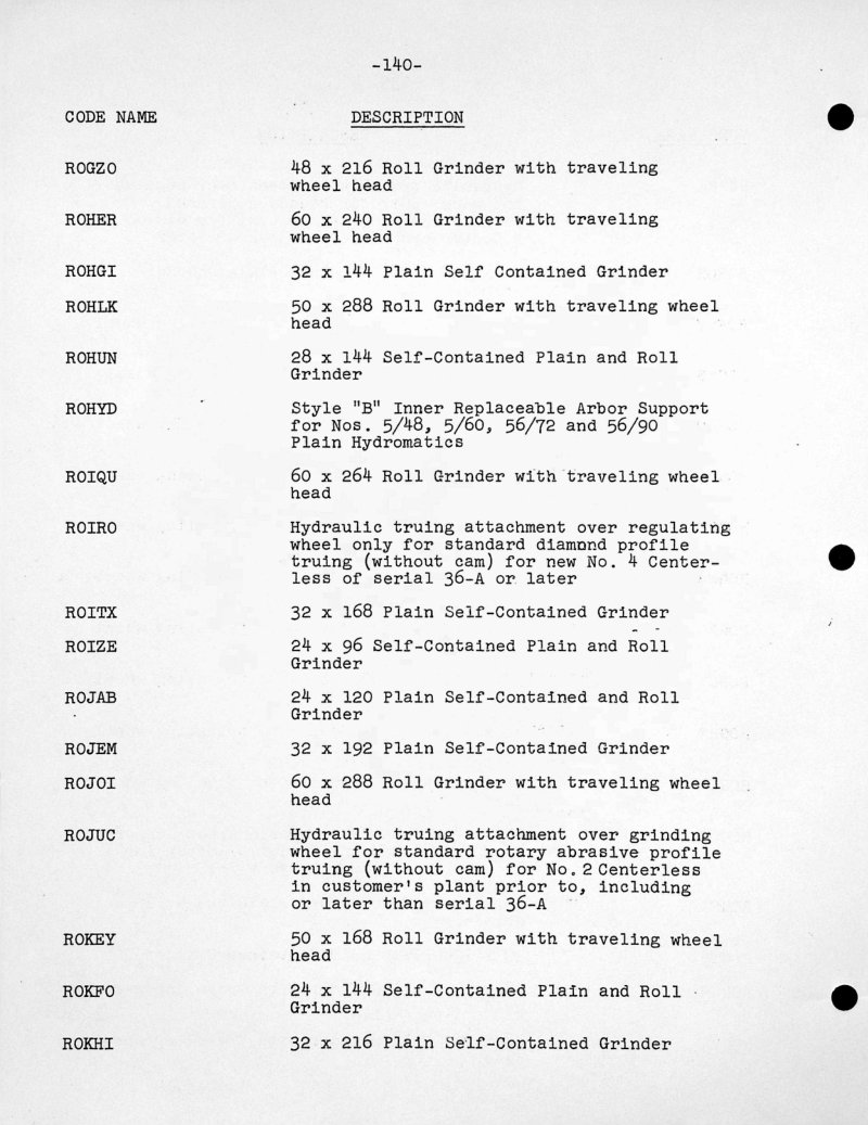
Code Book Alphabetical Listing Parts
Alphabetical code reference guide for Cincinnati grinding machines, accessories, and replacement parts. This technical resource provides machine model designation codes including ROGZO, ROHER, ROHGI, ROHLK, ROHUN and many others, each with full specification details covering dimensions and operational parameters. Covers grinder configurations ranging from plain self-contained units to roll grinders equipped with traveling wheel heads, plus component specifications for arbor supports, magnetic chucks, infeed workrests, and hydraulic trueing attachments. Pages 140–142 display codes ROGZO through ROREE. An essential reference for service technicians, maintenance personnel, and operators working with Cincinnati grinding equipment.
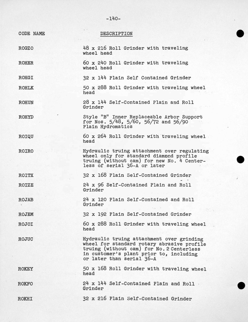
Code Book Alphabetical Listing Parts List
Alphabetical parts code reference for Cincinnati milling machines and accessories. This code book provides a systematic lookup guide to machine models, attachments, and replacement components across Cincinnati's product line. Pages 70–72 present coded designations with detailed descriptions of high-speed milling machines, universal millers, hydromatic milling equipment, and associated accessories—codes spanning HISAR through HOZRA with full model specifications. An essential reference for technicians, machinists, and workshop managers identifying parts and equipment in service records, repair work, and inventory management.
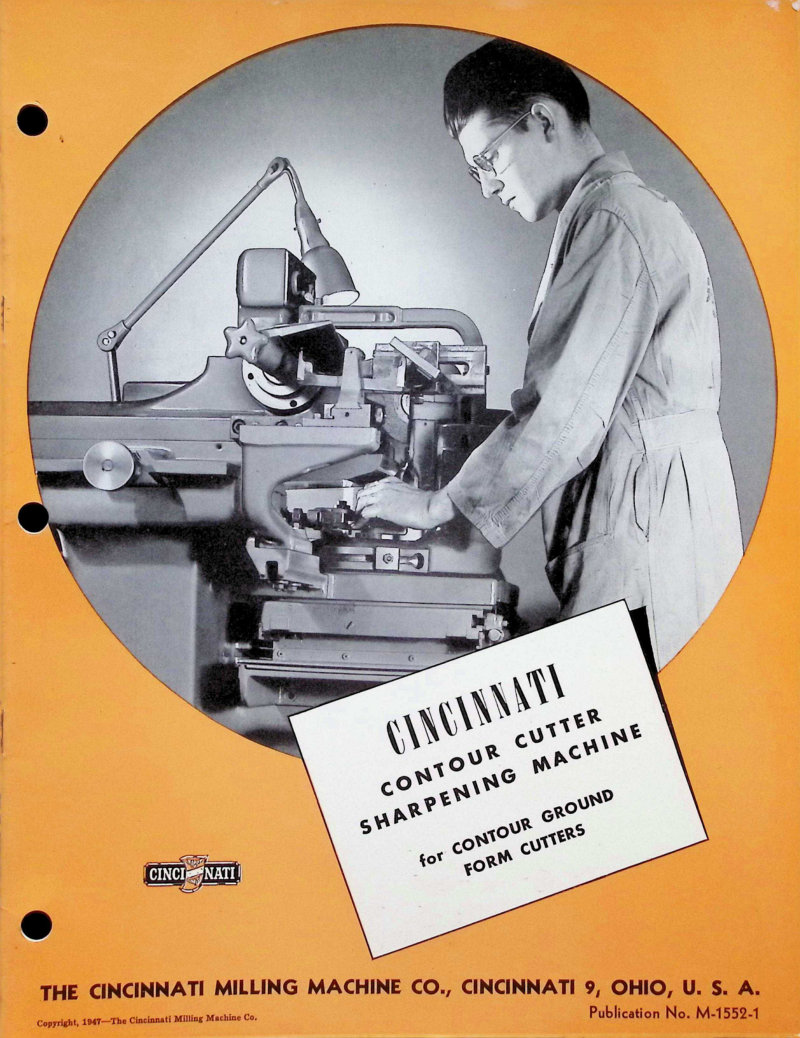
Contour Cutter Sharpening Machine Manual
Operational manual for the Cincinnati Contour Cutter Sharpening Machine, a precision tool designed for sharpening form cutters with controlled accuracy. This service manual covers complete operation and setup, beginning with detailed front-view assembly diagrams and an illustrated cover guide demonstrating proper operation and optimal working posture. The documentation highlights the machine's core grinding capabilities: contour grinding by profile matching, sheet metal template reproduction for consistent form control, and anti-friction slide mounting for smooth traverse. Key features include the built-in radius truing attachment, swivel mounting for flexible workpiece orientation, a simplified lead-generating device with interchangeable cams to accommodate various lead angles, rake angle compensation for precise cutting edge geometry, anti-friction slides throughout the mechanism, vertical slide adjustment for depth control, transverse positioning slide for lateral placement, and quick-change spindle nose for rapid tool changeover. The workshop manual provides the technical foundation needed to set up, operate, and maintain this specialized cutter sharpening equipment effectively.
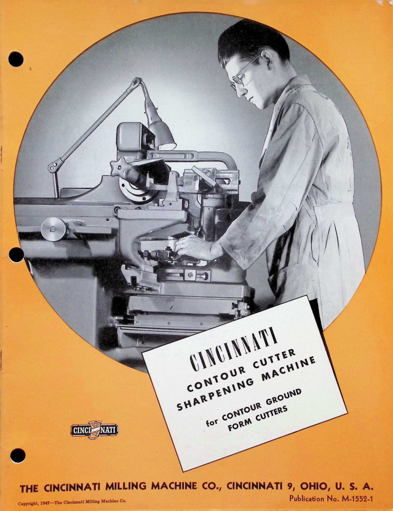
Contour Cutter Sharpening Machine Manual
Original operator and technical manual for the Cincinnati Contour Cutter Sharpening Machine, a precision tool designed for sharpening form cutters with contoured profiles. This service manual covers complete machine operation and design principles, including contour grinding technology, anti-friction slide mounting systems, and wheelhead operation. Details the lead generating device capable of producing various lead angles—30°, 40°, 50°, 60°, 80°, and straight (infinity)—essential for custom cutter geometry. Explains rake angle compensation methods and routine maintenance procedures to keep the machine in working order. Includes front and rear view photographs for quick machine familiarization and reference during setup and troubleshooting.

Cutting Gear Teeth on a Milling Machine
Instruction booklet for cutting worms, worm-wheels, spur, helical and bevel gear teeth on Cincinnati milling machines. This workshop manual describes the complete range of specialized equipment and accessories needed for precision gear cutting, including the Universal Dividing Head, Enclosed Driving Mechanism, Universal Spiral Milling Attachment, Circular Milling Attachment with Index Plate, and Gear Cutting Attachment. Provides detailed setup and operating procedures for each gear type and attachment configuration. Published by The Cincinnati Milling Machine Co., Cincinnati, Ohio. Copyright 1952. Table of Contents: - # Equipment for Cutting Gear Teeth on Cincinnati Milling Machines - Universal Dividing Head - Universal Spiral Milling Attachment - Enclosed Driving Mechanism - Circular Milling Attachment - Gear Cutting Attachment
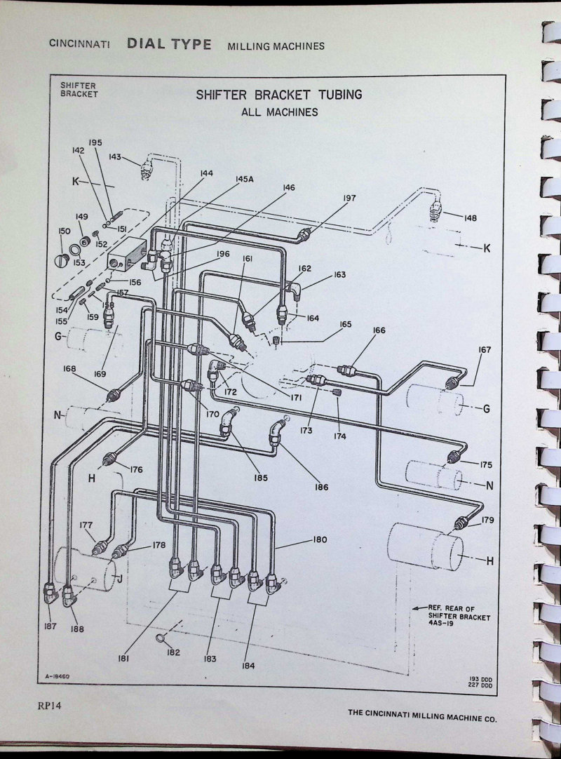
Dial Type Milling Machines Parts List
Parts list and technical documentation for Cincinnati Dial Type milling machines. This comprehensive parts manual includes detailed component diagrams for the shifter bracket tubing assembly (Unit 4AS), main drive motor assembly, and complete component identification with part numbers and quantities across all machine models. Essential reference for technicians performing maintenance, repair, or component replacement on Cincinnati Dial Type mills.
Dial Type Milling Machines Service Manual
Service manual and parts catalog for Cincinnati dial type milling machines, models 1, 2, 3, and 4 (medium speed and high speed variants). This workshop manual provides complete guidance on machine maintenance, setup, and repair. Includes detailed lubrication charts and procedures, installation instructions, and step-by-step adjustment protocols for clutches and traverse mechanisms. Contains thorough removal and reinstallation procedures for all major assemblies: spindles, feed mechanisms, gear shifters, coolant systems, and columns. Comprehensive parts lists cover every major assembly and subassembly, making this repair manual essential for shop technicians and machine operators performing maintenance or troubleshooting on these Cincinnati milling machines.
Filmatic 12", 14" & 18" Grinders Operator's Manual
Operator's instruction manual for Cincinnati Filmatic 12", 14" and 18" Universal Grinding Machines (Model LL), published by The Cincinnati Milling Machine Co., Grinding Machine Division, Cincinnati, Ohio (Publication No. G-674-1). This workshop manual covers setup, operation, and routine maintenance for precision grinding systems equipped with 12, 14 and 18 inch grinding wheels, providing essential reference for machine operators and maintenance personnel. Table of Contents: - Dimensional Drawings - Principal Machine Specifications - Standard Equipment—Supplied with the Machine - Installation Instructions - Lubrication - General Operating Instructions - Mounting and Balancing the Wheels - Trueing the Wheels - Regrinding Worn Work Centers - Recommendations on Cutting Fluids - Cleaning the Cutting Fluid Reservoir - Set-Ups for Unusual Types of Work - Safety Precautions - Maintenance Hints - Adjustments - Extras for Internal Grinding Head - Power Rapid Traverse Positioning - Ordering Repair Parts - Alphabetical Index
Filmatic UA Universal Grinding Machines Operator Manual
Operator's instruction manual for Cincinnati Filmatic and UA Universal grinding machines, covering 12", 14", 14H", and 18" models (Model DE). Publication No. G-805-1. This workshop manual provides illustrated guidance for machine setup, operation, and routine maintenance. Diagram reference numbers throughout enable quick location of specific technical information and component details. Serial number identification is stamped on the front of the machine base, positioned below the Cincinnati nameplate for warranty and service record purposes. Table of Contents: - Dimensional Drawing - Principal Machine Specifications - Standard Equipment Supplied with Machine - Installation Instructions - Lifting the Machine - Location of Machine - Foundation - Leveling Instructions - Bolting the Machine to the Foundation - Lubrication - Spindle Bearings - Table and Wheelhead Ways - Headstock Unit - Lubrication Diagram - Lubricating Instructions and Specifications - Internal Grinding Attachment - Oil Reservoirs - Oil Filters - Operating Instructions - Starting a New Machine for the First Time - Electrical Control Panel - Table Hand Operation - Table Power Feed Controls - Hand Cross Feed Controls - Power Rapid Positioning of Wheelhead - Automatic Pick Feed Mechanism - Functional Diagram - Two Speed Grinding Wheel Drive - Internal Grinding Attachment - Headstock - Lever and Hand Wheel Retraction of Footstock Center - Placing the Work in the Machine - Reversing Dogs - Back Rests - Center Rest - Swivel Table - Swiveling the Wheelhead - Truing the Grinding Wheel - Coolant Control Valve - Coolant Supply - Cleaning the Coolant Reservoir - Recommendations on Cutting Fluids - Mounting and Balancing the Wheels - Assembling the Grinding Wheel Mount - Balancing the Grinding Wheel
Final Report on High Temperature Machining Methods
Final report on high temperature machining methods from The Cincinnati Milling Machine Co., prepared for the Aeronautical Systems Division, Air Force Systems Command under contract AF33(600)40066. Documents research conducted from September 5, 1959 through October 11, 1962. This technical documentation serves as a workshop reference for advanced machining techniques developed during this multi-year aeronautical research program, prepared for the Fabrication Branch of the Manufacturing Technology Laboratory.
Gilbert Boring Mills Service Manual Parts 4A-505
Service manual for Cincinnati Gilbert boring mills covering complete operation and maintenance of parts 4A-505, AA-500, and AA-638. Provides installation and dismantling instructions essential for setup and rebuild work. Includes detailed lubrication and adjustment charts to keep the machine running at peak performance. Technical coverage spans column and base construction, arm elevation and clamping mechanisms, forward and reverse operation, spindle drive gearing systems, and drive gear shifting procedures. Addresses spindle and rack sleeve assembly, feed gearing configurations with and without tap leads, spindle feed clutch engagement, head clamp operation, and front head roller mounting. This workshop manual serves as the authoritative reference for technicians performing maintenance, repairs, or component replacement on these Cincinnati Gilbert boring mill models.
Gilbert Radial Boring Mills Operating Manual
Operating manual for Cincinnati Gilbert radial boring mills covering the full range of horizontal boring, drilling and milling operations on these heavy-duty floor-type machines. Provides detailed installation guidance, spindle head lubrication procedures using SAE 30 oil, and maintenance protocols for the column base unit with its metered oiling systems. Documents all 24 spindle speeds controlled via lever engagement, describes the 8 available spindle feeds and milling feeds, and explains hand operation techniques. Maintenance and troubleshooting sections address routine upkeep to keep the machine in reliable working condition. Includes technical references to drawings T-600, T-500, T-304, T-305-A and component designations throughout. Machine features #5 Morse Taper spindle nose. Essential workshop manual for operators and maintenance technicians responsible for Cincinnati Gilbert boring mill operation and care.
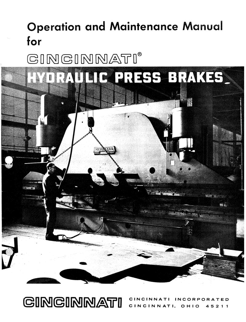
H-Series Hydraulic Press Brakes Operation Manual
Operation and maintenance manual for Cincinnati H-Series hydraulic press brakes. This workshop manual provides detailed guidance on machine identification, installation procedures, and proper lubrication practices. Covers all aspects of operation including starting the machine, controlling ram stroke and speed on both two- and three-speed models, managing tonnage settings, and fine-tuning ram leveling and tilt control. The maintenance section walks through hydraulic oil and filter care, magnetic trap cleaning, oil cooler servicing, piston vee and cup packing replacement, leveling band replacement, hydraulic pressure verification and adjustment, and troubleshooting erratic ram leveling behavior. Includes a practical capacity chart for 90-degree air bends in mild steel across die openings from 10 gauge to 1 inch, with tonnage ratings specified for different machine lengths. Essential reference for operators and maintenance technicians working with Cincinnati press brake equipment.
Heald 72A3-72A5 Service Manual
Complete service manual and repair parts documentation for Heald Style No. 72A3-72A5 internal grinding machines, covering Plain, Dial Indicator, and Extended Bridge configurations in both two-motor and three-motor drive versions, plus the No. 72A5 Universal Grinding Machine. This 91-page workshop manual includes everything needed for installation, lubrication schedules, machine setup, available attachments, maintenance adjustments, grinding wheel specifications, and wheelhead assemblies. Detailed service repair parts diagrams, functional schematics, lubrication flow charts, and cross-section drawings of all major machine units provide technicians with the reference material essential for troubleshooting and component replacement. Manufactured by Cincinnati, a recognized builder of precision grinding equipment. Table of Contents: - INSTALLATION - The Foundation - Clean the Machine - Aligning the Machine - Connect the Machine to Line - Attach Coolant Tank - Fill Hydraulic System - LUBRICATION - Table Force Feed Lubrication - Wheelhead Lubrication - Motor Lubrication - Lubrication Instructions - Lubrication Diagrams - SETTING UP THE MACHINE - Functional Diagrams - Attach Work Fixture - Adjust Coolant Attachments - Install Wheelhead and Adjust Drive - Adjust Truing Unit - True New Wheel - Set Grinding Stroke - Set Truing Stroke - Set Quick Return and Extreme Outward Table Travel - Test Grind for Straightness - Grind to Finish Size - Make Cross-slide Adjustments - Set Diamond for Size - Determine Compensation for Wheel Wear and Truing - Set Speeds and Feeds - Standard Grinding Cycle - Set Clutch and Brake Cam and Water Valve Cam on Two Motor Drive Machines - Setting Up No. 72A Dial Indicator Machines - Setting Up No. 72A5 Universal Machines - Internal Grinding, External Grinding, Face Grinding - Setting Up No. 72A5 Extended Bridge Machines - ATTACHMENTS - Workhead Cross-slide - Hand Wheel Table Feed - Sensitive Cam Facing Attachment - MAINTENANCE ADJUSTMENTS - How the Hydraulic System Operates - Maintenance of the Hydraulic System - Uneven Table Motion
Hydrashift Model LR Lathes Service Manual
Complete service manual and parts catalog for Cincinnati Hydrashift Model LR lathes, covering all standard sizes from 10" through 26" in engine and toolroom configurations. This workshop manual provides essential technical information for maintenance, troubleshooting, and repair work, including spindle nose and general dimensional specifications, preparation procedures, dedicated service tools reference, detailed lubrication schedules with approved lubricants list, functional diagrams, operating instructions, and a comprehensive repair parts catalog. 92 pages. Table of Contents: - DESCRIPTION - GENERAL SPECIFICATIONS - SPINDLE NOSE DIMENSIONS - GENERAL DIMENSIONS - PREPARATION FOR USE - SERVICE TOOLS - LUBRICATION - FUNCTIONAL DIAGRAMS - OPERATION - MAINTENANCE - LIST OF APPROVED LUBRICANTS - REPAIR PARTS
Hydromatic Milling Machines Operator's Manual
Operator's instruction book for Cincinnati Tracer-Controlled Hydromatic Milling Machines in Plain and Duplex versions. This service manual covers essential installation procedures including lifting, foundation preparation, bolting, and precision leveling to ensure proper machine setup. Operating sections detail startup sequences, table and spindle controls, and hydraulic system operation to help you run the machine safely and effectively. Maintenance guidance includes lubrication specifications and adjustment procedures for gibs, spindle bearings, clutch mechanisms, and motor drive chain. The manual also incorporates safety precautions and technical specifications, plus a standard equipment list for reference.
Hydromatic Milling Machines Service Manual
Service manual and parts list for Cincinnati Hydromatic milling machines, covering OL models in plain, duplex, and tracer-controlled versions. This comprehensive workshop manual includes identification, functional and dimensional diagrams, along with detailed coverage of spindle carrier, elevating bracket, pulley bracket, reverse box, motor drive, table, bed assembly, hydraulic unit, variable feed mechanisms, tracer valve, down-cutting attachment, and coolant pump with piping schematic. Features instruction plates and a variable displacement pump installation guide. 146 pages total. Table of Contents: - The Meaning of Hydro-Matic Milling Machine Sizes - Functional Diagrams - Dimensional Diagrams - Key Number Index - Conversion Chart (Inches into Millimeters) - How to Order Repair Parts - Spindle Carrier (Unit No. 3BV) - Elevating Bracket (Unit No. 3BT) - Pulley Bracket (Unit No. 3BJ) - Reverse Box (Unit No. 3BAC) - Motor Drive (Unit No. 3BN) - Table (Unit No. 3BAT) - Bed (Unit No. 3BB) - Hydraulic Unit—Plain and Duplex Machines (Unit No. 3BW) - Hydraulic Unit—Tracer Controlled Machines (Unit No. 4 BW) - Variable Feed and Positive Stop—Plain and Duplex Machines (Unit No. 3BAV) - Variable Feed and Positive Stop—Tracer Controlled Machines (Unit No. 4BAV) - Tracer Valve (Unit No. 4BFR) - Down Cutting Attachment (Unit No. 3BHP) - Coolant Pump and Piping (Unit No. 3BP) - Instruction Plates - Installing a Variable Displacement Pump (M-2216)
Hypro Boring Mills Erection Instructions
Erection instructions and comprehensive parts list for Cincinnati Hypro Boring Mills. This detailed workshop manual covers machine assembly, installation, and component identification, including title pages and a photograph of the complete boring mill assembly showing machine structure, spindle head configuration, work table layout, and hydraulic system components. Essential reference for technicians and operators performing setup and maintenance.
Lubricants Technical Data - Purchase Specifications
Technical data manual for Cincinnati Milacron machine lubricants, detailing purchase specifications and approved lubricant products. This service manual covers warranty information and product approval guidelines, ensuring operators and technicians select the correct lubricants for their equipment. Publication 10-SP-7421-1 supersedes earlier revision 10-SP-7421. An essential reference for maintenance planning and procurement. Table of Contents: - SELECTIVE INDEX
Lubricants Technical Data and Products
Technical reference guide for Cincinnati machine tool lubricant specifications and approved products. Publication 10-SP-80160-2 supersedes all previous editions. Establishes purchase specifications and qualified product designations (P-35 through P-79) across lubricant categories—gear oils, hydraulic oils, spindle oils, and greases—for proper maintenance of Cincinnati machine equipment. Includes military specification equivalents and cross-reference tables, plus detailed test procedures for thermal stability evaluation and oil cleanliness standards to ensure correct lubricant selection and performance on the shop floor. Table of Contents: - Introduction - General Information - Selective Index - P-35 (C-460) Extra Heavy E.P. Gear Lubricant - P-38 (HL-32) Light Hydraulic Oil and Lubricant - P-45 (FC-22) Light Spindle Oil - P-47 (G-68) Heavy-Medium Way Oil - P-50 (G-220) Heavy Way Oil - P-53 (HG-32) Combination Hydraulic and Way Oil - P-54 (HL-68) Heavy-Medium Hydraulic Oil and Lubricant - P-55 (HL-46) Medium Hydraulic Oil and Lubricant - P-57 (HL-150) Heavy Hydraulic Oil and Lubricant - P-59 (C-320) Heavy E.P. Gear Lubricant - P-62 (FC-10) Very Light Spindle Oil - P-63 (C-68) Light E.P. Gear Lubricant - P-64 (X-2) Lithium Base General Purpose Grease - P-65 (FC-2) Extra Light Spindle Oil - P-68 (HM-32) Light Anti-Wear Hydraulic Oil and Lubricant - P-69 (HM-68) Heavy-Medium Anti-Wear Hydraulic Oil and Lubricant - P-70 (HM-46) Medium Anti-Wear Hydraulic Oil and Lubricant - P-72 (X-1) Lithium Base Extreme Pressure Grease - P-74 (C-220) Heavy-Medium E.P. Gear Lubricant - P-76 (C-100) Medium-Light E.P. Gear Lubricant - P-77 (C-150) Medium E.P. Gear Lubricant - P-78 (C-1000) Super-Heavy E.P. Gear Lubricant - P-79 (X-0) Lithium Base Extreme Pressure Grease - Military Specification Equivalents - Thermal Stability Test Procedure "A" - Thermal Stability Test Procedure "B" - Cincinnati Milacron Inc. Lubrication Heat Test Standards (Copper & Steel) - Oil Cleanliness and Control
Lubrication Manual - 1968 Edition
Lubrication manual for Cincinnati Milling Machine Co. production equipment, revised November 1967. This 1968 edition provides comprehensive lubrication specifications for all machine types in the Cincinnati lineup, with 20 detailed specification sheets (P-35 through P-72) that outline purchase requirements and approved lubricant products for proper maintenance. Includes summary guidance and technical reference notes to support correct servicing across all models. Publication No. M-2258-6. Essential workshop reference for Cincinnati machine maintenance and trouble-free operation. Table of Contents: - P-35 - P-38 — supersedes P-36, P-39 and P-56 - P-45 — supersedes P-46 - P-47 — supersedes P-52 - P-50 — supersedes P-41 - P-53 - P-54 — supersedes P-52 - P-55 — supersedes P-31 - P-57 - P-59 - P-62 - P-63 - P-64 — supersedes P-37 and P-43 - P-65 - P-67 - P-68 - P-69 - P-70 - P-71 - P-72 - Summary - Notes
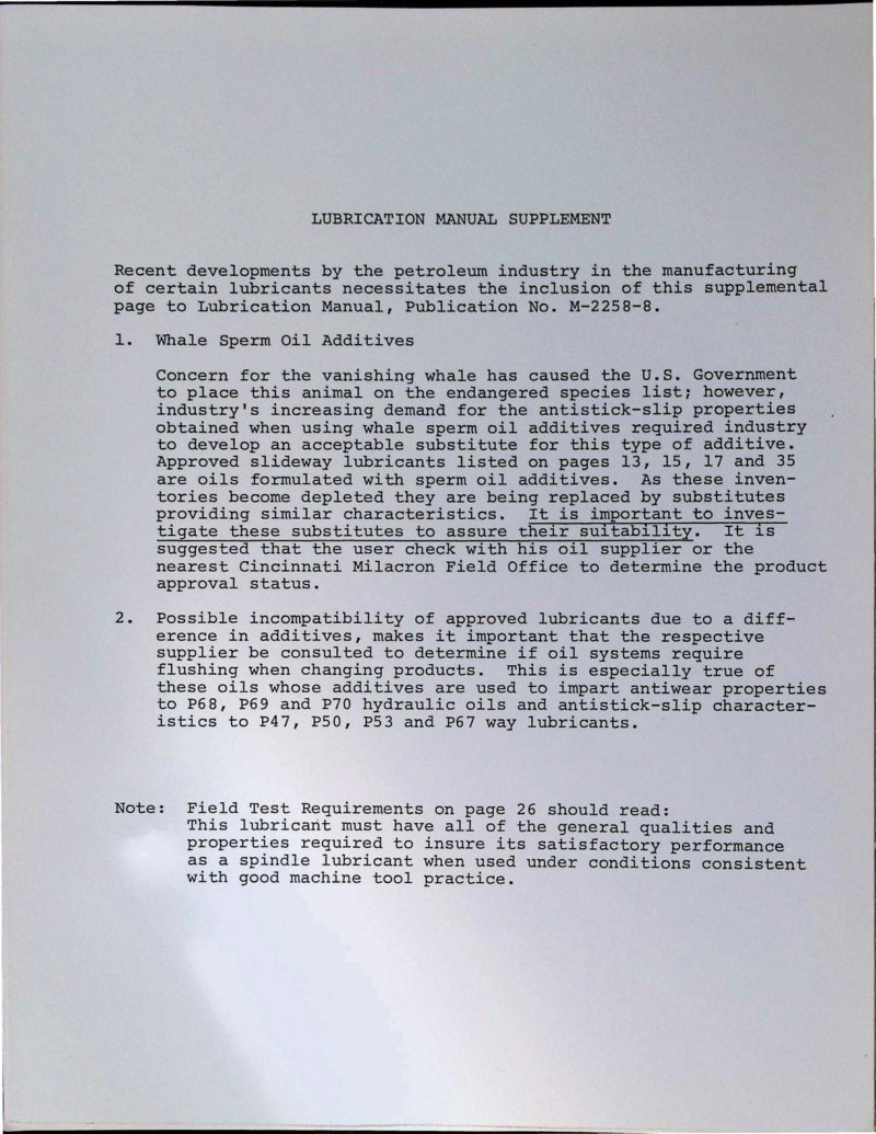
Lubrication Manual - 8th Edition
Lubrication manual for Cincinnati Milacron industrial machines, 8th edition. Provides comprehensive guidance on purchase specifications and approved lubricant products for machine lubrication systems. Includes a supplement addressing sperm whale oil additives, alternative lubricant formulations, and compatibility issues when mixing approved lubricants with different additive packages. Specifies detailed requirements for hydraulic oils P68, P69, P70 and way lubricants P47, P50, P53, P67. Essential reference for maintenance technicians and plant engineers responsible for machine upkeep and fluid management. Table of Contents: - # Descriptive Index - CMCo. Spec. No. P-35 - CMCo. Spec. No. P-38 (Supersedes P-36, P-39 and P-56) - CMCo. Spec. No. P-45 (Supersedes P-46) - CMCo. Spec. No. P-47 (Supersedes P-52) - CMCo. Spec. No. P-50 (Supersedes P-41) - CMCo. Spec. No. P-53 - CMCo. Spec. No. P-54 (Supersedes P-52) - CMCo. Spec. No. P-55 (Supersedes P-31)
Lubrication Manual for All Machines
Seventh edition lubrication manual for Cincinnati Milling Machine Company industrial machinery. This comprehensive workshop reference details purchase specifications and approved lubricant products for proper maintenance of all machines manufactured by Cincinnati Milling Machine Co. Revised July 1969. An essential service manual for technicians and operators responsible for equipment upkeep and preventive maintenance schedules. Table of Contents: - # Descriptive Index - P-35 - P-38 - P-45 - P-47 - P-50 - P-53 - P-54 - P-55
Lubrication Manual M-1931-2
Approved lubricants manual for all Cincinnati Milling Machine Co. and Cincinnati Grinders Incorporated equipment, Publication No. M-1931-2 (copyright 1956). This service manual specifies lubricants tested and approved by the company's laboratory and engineering departments through rigorous laboratory and field testing protocols. It covers lubrication recommendations for Cincinnati milling machines and grinding equipment, with products distributed nationally and internationally. An essential maintenance reference for proper lubrication of industrial machine tools.
Machine Tool Indicator Plates Symbols Manual
Reference manual for Cincinnati machine tool indicator plates and control interface symbols. Provides standardized symbol sets based on ISO Recommendations R369 and ANSI B5.46 standards, covering all common machine operation instruction plates. Includes detailed guidance on directional indicators for linear movement, rotational motion, feed rates, operating cycles, and spindle rotation orientation. Essential reference for technicians, operators, and maintenance personnel working with Cincinnati machine tools, ensuring correct interpretation of control symbols across different equipment configurations.
Machine Tool Indicator Plates Symbols Manual
Technical reference manual for Cincinnati machine tool indicator plates, providing the complete standardized symbol set used across industrial manufacturing documentation. This manual covers fundamental operational symbols including movement directions and speed indicators, rotation types, feed rate specifications, and all related machine tool notation conventions. Essential for technicians, operators, and maintenance personnel who need to accurately interpret control panel markings and technical diagrams on Cincinnati equipment. Publication No. M-5082.
Machining Center Tooling Systems Technical Data
Technical data manual for tooling systems engineered for Cincinnati Milacron automatic tool changer installations. This workshop reference covers the complete range of integral shank tooling including collet chucks, floating chucks, boring chucks and bars, end mill adapters, tap chucks with torque control and compensation mechanisms, morse taper and jacobs taper adapters, spade drills, and pre-set tooling assemblies. Detailed technical illustrations show shell mill adapters, collet chucks, collet specifications with installation locations, and dimensional data for each tooling configuration. Essential for technicians setting up, troubleshooting, or maintaining Cincinnati Milacron machining centers and their integrated automatic tool changing systems. Table of Contents: - SECTION I—INTEGRAL SHANK TOOLING - Collet Chucks - Floating Chucks - Boring Chucks and Bars - End Mill Adapters - Tap Chucks - Morse Taper Adapters, Spade Drills & Jacobs Taper Adapters - Adapter For Adjustable Adapter Shanks & Kwik-Switch Conversion Adapter - Engineering Data - SECTION II—PRE-SET TOOLING - Basic Holder - Collet Chucks - Morse and Jacobs Taper Adapters - Floating Chucks - Boring Head Adapters - End Mill Adapters - Tap Chucks - Boring Chucks and Bars - SECTION III—COLLETS AND TOOLING ACCESSORIES - Collets - Collet Sets - Pre-Setting Height Gage & Pull Back Knob - Tool Locking Fixture
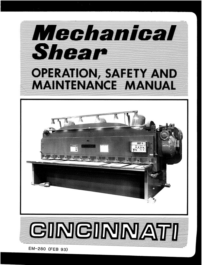
Mechanical Shear Operation, Safety and Maintenance Manual
Operation, safety and maintenance manual for Cincinnati mechanical shear 10 series. Covers machine identification and specifications, installation procedures, lubrication requirements, and comprehensive safety rules for shop floor operations. Details standard controls, gauges, and optional accessories available for this model. Includes machine control configurations for units shipped between October 1974 and January 1975. The maintenance and adjustment sections provide step-by-step guidance on blade replacement, clearance adjustments, ram adjustment, clutch operation, and brake adjustment. Troubleshooting section helps diagnose and resolve common operational issues. Features detailed diagrams and schematics showing the layout and interconnection of all 10 series shear components.
Milacron Toolmaster Service Manual
Cincinnati Milacron Toolmaster service manual and parts list (Publication No. M-2318-3) covering maintenance, repair, and operation of these precision milling machines. Includes detailed safety precautions, step-by-step instructions for operators and maintenance technicians, cross-references to related safety documentation, and compliance notes with applicable federal regulations. 72 pages.
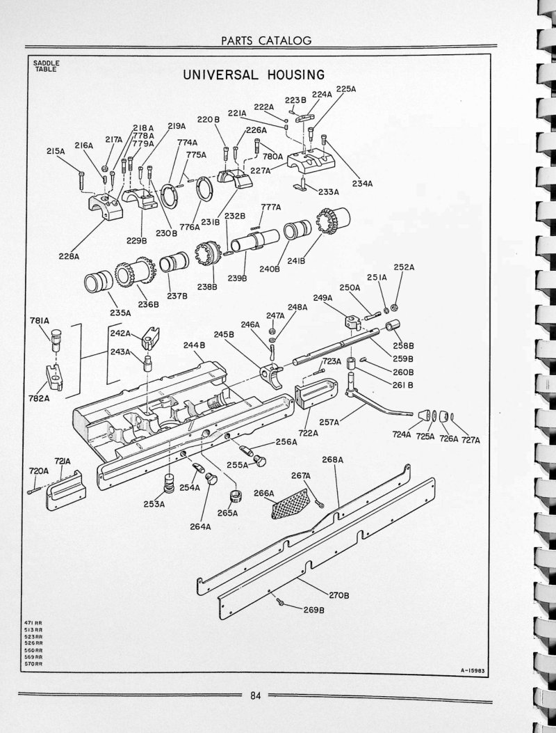
ML/MI 200-400 Series Milling Machines Parts List
Parts catalog for Cincinnati ML and MI milling machines (200, 300, and 400 series). Contains exploded views of the universal housing for saddle table assembly with detailed component labeling (parts 215A through 780A, 782A, spindle nose assemblies, bearings, gears, and associated hardware). Includes identification of all parts with part numbers and machine model applicability (203-10, 205-12, 307-12, 307-14, 410-14 machines).
Model ED Centerless Lapping Machine Parts List
Parts list and service documentation for the Cincinnati Model ED Centerless Lapping Machine. This catalog provides functional diagrams with front and rear views of the complete machine, identifying all major assemblies and component locations including the lapping wheel truing cross slide, work rest, regulating wheel truing cross slide, wheelhead, spindle, drive box, hydraulic unit, coolant tank, and control panel. Essential reference for parts identification, ordering, and machine maintenance work.
Model ER Hydraulic Universal Grinding Service Manual
Service manual and parts list for Cincinnati 12", 14", 16" and 18" Model ER Hydraulic Universal Grinding Machines. Covers setup and maintenance procedures for the internal attachment spindle, table operating pistons, cross feed backlash eliminator, footstock spindle, and grinding wheel spindle bearings with thrust bearing support. Includes detailed adjustment instructions for the wheel spindle V-belt drive, headstock motor and spindle drive V-belts, headstock motor unibrake, hydraulic oil pressure regulation, internal grinding attachment belt drive, and table ways lubrication system. Features dimensional engineering drawings with front and rear views, cross feed handwheel and pickfeed mechanism diagrams, operating control knobs and levers, complete hydraulic circuit schematics covering both servo table control and hand table control modes, and inches-to-millimeters conversion chart. Publication No. G-547, Identification No. 2U-DO. Copyright 1946. Table of Contents: - ADJUSTMENTS - To Adjust Alignment of Internal Attachment Spindle - Alignment of Table Operating Pistons - Cross Feed Backlash Eliminator - Footstock Spindle - Gibs - Grinding Wheel Spindle Bearings - Grinding Wheel Spindle Thrust Bearing - Grinding Wheel Spindle V-Belt Drive - Headstock Motor Drive V-Belts - Headstock Motor Unibrake - Headstock Spindle Drive V-Belts - Hydraulic Oil Pressure - Internal Grinding Attachment Belt Drive - Volume of Oil to Table Ways - Wheel Slide - CONVERSION CHART (Inches to Millimeters) - DIAGRAMS AND ILLUSTRATIONS - 19" Hydraulic Universal Grinder - Dimensional Drawing - Right Front View - Right Rear View - Left Rear View - 14", 16", 18" Hydraulic Universal Grinders - Dimensional Drawing - Floor Plan and Leveling Instructions for 14", 16", 18" x 72" Grinders - Left Rear View - Right Front View - Right Rear View - 12", 14", 16", 18" Hydraulic Universal Grinders - Cross Feed Handwheel and Pickfeed Mechanism - Operating Control Knobs and Levers - Schematic Layout of Table Ways Lubrication System - Hydraulic Circuits (Insert at back of book) - With Servo Table Control - Explanation - With Hand Table Control - Explanation
Model LL Hydraulic Universal Grinding Service Manual
Service manual and comprehensive parts list for Cincinnati Filmatic 12", 14", and 18" Hydraulic Universal Grinding Machines, Model LL. This workshop manual covers detailed adjustment procedures and complete dismantling instructions for all major hydraulic assemblies, including the valve body, pilot valve, relief valve, reverse valve, selection valve, and start/stop valve mechanisms. Also addresses the crossfeed handwheel assembly, headstock spindle, pickfeed unit, power rapid traverse infeed assembly, speed control system, table cylinder and traverse mechanism, wheelhead oil pump and spindle drive, worm and worm wheel gearing, crossfeed body, and wheelhead speed control driving ring. Includes dimensional engineering drawings and a conversion chart for reference. 141 pages. Identification numbers 2U and 3U-DE, Publication G-698. Table of Contents: - ADJUSTMENTS - Alignment of Internal Grinding Attachment Spindle - Alignment of Table Operating Pistons - Crossfeed Backlash Elimination - Gibs - Grinding Wheel Spindle Bearings - Grinding Wheel Spindle Thrust Bearing - V – Belt Drive - Headstock Motor Drive V – Belts - Unibrake - Spindle Drive V – Belts - Thrust Bearing - Hydraulic Oil Pressure - Internal Grinding Attachment Belt Drive - Volume of Oil to Table Ways - Wheel Slide - CONVERSION CHART - DIMENSIONAL DRAWINGS - DISMANTLING INSTRUCTIONS - To Dismantle Hydraulic Valve Body Check Valve Plungers and Ball Check Valves - Pilot Valve - Rake and Tarry Valves - Relief Valve - Reverse Valve - Selector Valve - Start and Stop Valve - To Lift Headstock from Table - To Remove and Dismantle Crossfeed Handwheel Assembly - Footstock - Headstock - Headstock Spindle (12" Grinders) - Pickfeed Unit - Power Rapid Traverse Infeed Assembly - Rapid Traverse Infeed Assembly (Hand Operated) - Speed Control (12" Grinders) - Table Cylinder - Traverse - Wheelhead Oil Pump - Spindle (12" Grinders) - Worm and Worm Wheel - Crossfeed Body - Hydraulic Valve Body - Wheelhead - To Set Speed Control Driving Ring
Monoset Cutter and Tool Grinder Owner's Manual
Owner's manual and operator's instruction book for the Cincinnati Monoset Cutter and Tool Grinder, a precision cylindrical grinding machine. This workshop manual provides comprehensive guidance on proper machine operation, routine maintenance procedures, and critical adjustments needed to preserve grinding accuracy and extend service life. Covers setup, coolant management, workholding techniques, and troubleshooting for reliable tool and cutter grinding work. An essential reference for machine operators and maintenance technicians. Publication No. M-1447-1, copyright 1945.
MT Toolmaster Milling Machines Operator's Manual
Operator's instruction book for Cincinnati MT Toolmaster milling machines. Covers manual drive machines, one axis mechanical drive machines, two axis mechanical drive machines, and three axis DC drive machines. Publication No 8006E. Includes sections on installation, operation, and maintenance.
MT Toolmaster Milling Machines Operator's Manual
Operator's instruction manual for Cincinnati Milacron MT Toolmaster milling machines (Publication No. 8006E). This workshop manual provides comprehensive operating guidance for all standard configurations of the MT Toolmaster line, covering manual drive models, single-axis mechanical drive machines, dual-axis mechanical drive units, and three-axis DC drive systems. Essential reference for machine operators and maintenance personnel working with these precision industrial milling tools.
No. 0-8 Plain Automatic Milling Machine Owner's Manual
Operator's instruction book for the Cincinnati No. 0-8 Plain Automatic Milling Machine, Publication M-1645 from The Cincinnati Milling Machine Company in Cincinnati, Ohio. This manual covers machine operation, setup, and maintenance procedures for the No. 0-8 milling machine. Dated 1948, it includes photographic illustrations of the standard machine configuration and technical details of the optional hydraulic rise-and-fall mechanism available for the spindle carrier. An essential reference for operators and technicians responsible for day-to-day operation and care of this precision milling equipment.
No. 1 Toolmaster Milling Machine Service Manual
Complete service and repair manual with integrated parts list for Cincinnati No. 1 Toolmaster milling machines covering Models 1A, 1B, 1C (Model LO), 1D (Model LA), and 1E (Model LR). Identification No. 6J-DK, Publication No. M-2109. This workshop manual includes functional schematic diagrams, detailed dimensional drawings, inch-to-metric conversion reference, and comprehensive lubrication specifications. It provides step-by-step installation guidance and full dismantling instructions for critical assemblies including V-belt housing, spindle sleeve, drive spindle assembly, spindle housing, spiral gear shaft, transmission shaft, speed change mechanism, overarm, and turret components. An essential technical resource for technicians performing service work, repairs, or scheduled maintenance on these classic Cincinnati milling machines. Original 1960 publication. Table of Contents: - FUNCTIONAL DIAGRAMS - DIMENSIONAL DRAWING - CONVERSION CHART (Inches to M/M) - LUBRICATION DIAGRAM AND SPECIFICATIONS - CMMCo. RECOMMENDED LUBRICANTS - INSTALLATION INSTRUCTIONS - ADJUSTMENTS - To Adjust Gibs - Drive Belts: Styles 1-A, 1-B - Drive Belt: Style 1-E - Backlash Eliminator - Quill Powerfeed Clutch: Style 1-B - Shaping Attachment Drive Belt - Shaping Attachment Gib - DISMANTLING INSTRUCTIONS - To Remove V-Belt Housing: Styles 1-A, 1-B - Style 1-D - Style 1-E - Splined Spindle Sleeve: Styles 1-A, 1-B - Drive Spindle Assembly: Style 1-A - Style 1-B - Styles 1-D, 1-E - Spindle Housing with Spindle: Styles 1-A, 1-B - Styles 1-D, 1-E - Spiral Gear Shaft: Style 1-B - Transmission Shaft: Style 1-B - Speed Change Assembly: Style 1-D - and Dismantle Powerfeed Housing: Styles 1-D, 1-E - Overarm and Turret: Styles 1-A, 1-B, 1-D, 1-E - Overarm (Heavy Duty): Style 1-C - and Dismantle Overarm Gear Housing: Style 1-C
No. 1½ Cutter Grinder Parts List and Service
Parts list and service manual for the Cincinnati No. 1½ Plain and Universal Cutter Grinder, manufactured by The Cincinnati Milling Machine Co. This repair documentation provides a complete nomenclature chart and detailed component breakdown across all major assemblies—column parts, countershaft parts, grinding attachments, and work head assemblies. Includes the machine serialization code identification system and step-by-step procedures for ordering replacement parts by serial number and specification data. Essential reference for workshop technicians and machine maintenance.
No. 2 & 3 High Power Millers Parts List
Parts list and service repair book for Cincinnati No. 2 and No. 3 High Power plain-universal-vertical millers. Published by The Cincinnati Milling Machine Co., Cincinnati, Ohio. Contains detailed parts lists with nomenclature charts, assembly diagrams, and component specifications for repair and maintenance. Includes sections for arbors, wrenches, belt drive systems, countershaft parts, drive box assemblies, feed systems, and various mechanical components.
No. 2 and 3 Centerless Grinding Machines Service Manual
Service manual and parts list for Cincinnati Filmatic No. 2 Model LO and No. 3 Model LL centerless grinding machines. This workshop manual covers essential adjustments and maintenance procedures including grinding wheel motor sheave alignment, arc-type lift fixture operation, backlash nut adjustment, cam infeed attachment setup, compensating sizing device calibration, electro-hydraulic infeed attachment tuning, gib alignment, grinding wheel spindle bearing maintenance, complete lubrication procedures, infeed workrest positioning, long bar attachment configuration, profile hydraulic truing unit operation, race grinding attachment use, roller infeed attachment adjustment, and grinding wheel motor V-belt tension. Includes dimensional drawings, functional diagrams, and detailed lubrication diagrams to support troubleshooting and repair. Valid for machines with serial numbers beginning 2M or 3M. Essential reference for technicians performing routine service or addressing alignment and wear issues on these precision centerless grinders. Table of Contents: - ADJUSTMENTS - To Adjust Alignment of Grinding Wheel Motor Sheave - Arc Type Lift Fixture - Badash Nut - Cam Infeed Attachment - Compensating Sizing Device - Electro-Hydraulic Infeed Attachment - The Gibs - Grinding Wheel Spindle Bearings - Balancer Wheelhead - Non-Balancer Wheelhead - To Adjust Grinding Wheel Spindle Lubricating Oil Pressure - Grinding Wheel Spindle Thrust Bearing - Balancer Wheelhead - Non-Balancer Wheelhead - To Adjust Infeed Workrest - Long Bar Attachment - Type "A" - Long Bar Attachment - Type "B" - Long Bar Attachment - Type "C" - Long Bar Attachment - Type "D" - Low Thrufeed Workrest - Profile Hydraulic Trung Unit - Race Grinding Attachment - Regulating Wheel Spindle Bearings - Roller Infeed Attachment - Tension of Grinding Wheel Motor V-Belts - Tension of Hydraulic Unit Motor V-Belt - Thrufeed Workrest - DIAGRAMS AND ILLUSTRATIONS - Dimensional Drawing - No. 2 Machine - Dimensional Drawing - No. 3 Machine - Functional Diagram - No. 2 Machine - Functional Diagram - No. 3 Machine - Functional Diagram - Rear View - Lubrication Diagram
No. 2 Centerless Grinding Machine Service Manual
Comprehensive service manual and parts list for Cincinnati No. 2 Centerless Grinding Machine, Models EA and OM (Identification No. 2M-DE, Publication No. G-522-3). This 176-page workshop manual provides detailed technical guidance on machine setup and maintenance, covering adjustment procedures for backlash compensation, pilot wheel alignment, friction clutch engagement, gibs, spindle and thrust bearings, oil pressure regulation, V-belt drive tensioning, hydraulic wheel truing, relief valve settings, infeed screw positioning, grinding wheel speed calibration, and infeed attachment configuration. Includes comprehensive instructions for installing and operating optional attachments: automatic infeed system, reciprocating attachment, infeed work rest, hand ejector, precision slide indicator, long bar attachments, and bar grinding attachment. Technical diagrams encompass dimensional drawings, front and rear elevation views, and detailed lubrication schematic. Dismantling procedures cover the automatic infeed attachment, feed box assembly, grinding wheel spindle, truing attachment mechanism, hydraulic reciprocating attachment, and intermediate shaft. Concludes with ball bearing specification data and complete index for quick reference. Table of Contents: - ADJUSTMENTS - To Adjust Backlash at Pilot Wheel - To Adjust Friction (Safety) Clutch - All Gibs - Grinding Wheel Spindle Bearings - Grinding Wheel Spindle Thrust Bearing - Grinding Wheel Spindle Lubricating Oil Pressure - Grinding Wheel Spindle V-Belt Drive - Hydraulic Piping Attachment Relief Valve - Infeed Nut on Slide Adjusting Screw - Regulating Wheel Speed - Regulating Wheel Spindle Bearings - Stroke on Automatic Infeed Attachment - And True Grinding Wheel - And True Regulating Wheel - To Set and Adjust Hydraulic Reciprocating Attachment - To Align Prefeed Work Guides and Dress Wheels - ATTACHMENTS - Automatic Infeed, Push-Button Compensating Sizing Devices - Grinding Wheel Reciprocating Attachment - Infeed Work Rest—Automatic Ejector Attachment - Infeed Work Rest—Hand Ejector Attachment - Precision Slide Indicator Attachment - Precision Work Rest Attachment - Type "A" Long Bar Attachment - Type "B" Long Bar Attachment - Type "C" Bar Grinding Attachment - BALL AND ROLLER BEARING DATA - DIAGRAMS AND ILLUSTRATIONS - Dimensional Drawing - Front View - Rear View - Lubrication Diagram - DISMANTLING INSTRUCTIONS - Remove and Dismantle Automatic Infeed Attachment - Feed Box - Grinding Wheel Spindle - Grinding Wheel Truing Attachment (Hydraulic Profiling) - Hydraulic Reciprocating Attachment - Intermediate Shaft
No. 2 Centerless Grinding Machine Service Manual
Service Manual and Parts List Catalog for Cincinnati No. 2 Centerless Grinding Machine, Models EA and OM (Identification 2M-OR, Publication G-522-2). Document covers adjustments (backlash, clutch, gibs, bearings, thrust bearing, oil pressure, belt drive, hydraulic relief, infeed nut, wheel speed regulation, stroke adjustment, truing and dressing wheels). Includes attachments (automatic infeed, grinding wheel reciprocating, infeed work rest with ejectors, precision slide indicator, thrufeed work rest, long bar attachments, bar grinding attachment). Contains dismantling instructions for automatic infeed attachment, feed box, grinding wheel spindle, truing attachment, hydraulic reciprocating attachment, and intermediate shaft. Includes dimensional drawing, front view, rear view, and lubrication diagram. Ball and roller bearing data included. 176 pages total. Copyright 1944.
No. 2 Cutter and Tool Grinder Operating Manual
Operating manual for the Cincinnati Milacron No. 2 Cutter and Tool Grinder, Models EA and OM. This workshop manual covers complete setup procedures, operational guidelines, lubrication schedules, and precision adjustment techniques for milling cutters and tool grinding work. Includes detailed instructions for equipment configuration and maintenance. Publication M-737-10. Original copyright 1943 by The Cincinnati Milling Machine Co. Table of Contents: - Machine Specifications - Standard Equipment - Installation Instructions - Lubrication - Starting the Machine for the First Time - Operating Instructions - Safety Precautions - Clearance Angles for Milling Cutters - Cutter Elements - Grinding Cutters - Grinding Reamers - Attachments - Recommendations for Grinding of Cutters for Carbide Milling - Salvaging Milling Cutters - Adjustments - Old Style Machines - Equipment Supplied at Extra Cost - Attachment Parts - Grinding Wheels - Tables - Clearance Angle Record - Ordering Repair Parts - Alphabetical Index
No. 2 Cutter and Tool Grinder Operator's Manual
Operator's manual for the Cincinnati No. 2 Cutter and Tool Grinder, covering essential machine operation, power table traverse systems, and standard grinding attachments. This workshop manual provides detailed instructions for proper machine handling and setup to ensure safe and accurate grinding work. Publication No. M-1051-2. Table of Contents: - General Specifications - Standard Equipment - Installation Instructions - Assembling the Machine - Unpacking - Setting Up Machine - Attaching the Tool Post to the Slide - Lubrication - Lubrication - Operating the Machine - Starting the Machine for the First Time - Operating Instructions - Electrical Controls - Table Traverse - Handwheel Cross Slide - Vertical Adjustment - Carriage Lock Levers and Leadscrew - Grinding Wheel Colors - Selecting the Wheelhead - Dressing the Grinding Wheel - Belt Tensioning Wheelhead Speed Diagram - Spindle Adjustment - Coolant System - Grinding Wheels - Direction of Wheel Rotation - Speed Selection - Clearance Setting Dials and Dial - Feed Pressure - Load Meter - Safety Precautions - Clearance Angles - Grinding Various Materials - Plain Milling Cutter - End Mill - Side Milling Cutter - Keyway Cutter - Slitting Saw - Side Milling Cutter - Angular Cutter - Small Diameter Meal Cutting Saws
No. 2 Cutter and Tool Grinder Operator's Manual
Operator's manual for the Cincinnati No. 2 Cutter and Tool Grinder, Model DO. Published by The Cincinnati Milling Machine Co. in 1967. This workshop guide covers essential setup procedures and operational instructions for running the machine tool, making it an invaluable reference for machinists and tool room operators responsible for grinding cutting tools and maintaining precision work. A foundational document for anyone working with this classic Cincinnati grinding equipment. Table of Contents: - Dimensional Drawing - General Specifications - Standard Equipment - Installation Instructions - Lifting the Machine - Foundation - Leveling - Assembling the Table and Table Slide - Lubrication - Lubrication Diagram - Lubrication Instructions and Specifications - Operating Instructions - Electrical Controls - Functional Diagram - Starting the Machine - Table Traverse Controls - Table Dogs - Engaging Power Table Traverse - Cross Traverse Controls - Wheelhead Vertical Controls - Wheelhead Swivel Adjustments - Swivel Table Adjustments - Swiveling the Table 180 Degrees - Changing Spindle Speeds - Direction of Spindle Rotation - Truing the Grinding Wheel - Grinding Wheels - Before Mounting the Grinding Wheel - Wheel and Flange Diameters - Mounting the Grinding Wheel - Tightening the Collet Nut - Mounting the Grinding Wheel and Collet Assembly - Starting the Grinding Wheel Spindle - Removing the Collet - Tailstocks - Workhead - Setting Up the Workhead and Tailstocks - Tooth Rests - Center Height Gage - Safety Precautions - Milling Cutter Clearance Angles
No. 2 Cutter and Tool Grinder Parts List
Parts list and ordering catalog for the Cincinnati No. 2 Cutter and Tool Grinder, Model EM (Identification 1D-LD), published by The Cincinnati Milling Machine Co. in Cincinnati, Ohio. This parts manual covers machines manufactured prior to 1947 and includes serial number reference data essential for identifying and ordering correct replacement components. The document is structured for tool crib organization and parts checkout procedures, making it practical for shop floor use and maintenance planning. Applicable specifically to machines equipped with a deep pocket in the front base but without one-shot lubrication system. Original factory reference material for grinding machine service and parts replacement. Table of Contents: - SERVICE INSTRUCTIONS - Lubrication Chart, Instructions and Specifications - Nomenclature Chart - Installation Instructions - Leveling - Adjusting the Work Head Spindle Bearings - Adjusting the Belt Tension - Removing the Table and Table Slide - Removing the Cross Feed Screw and Saddle - Removing the Wheel Head and Column - Removing the Sleeve on Column - Removing the Housing - Removing the Spindle Unit - Replacing the Main Driving Belt - Removing the Wheel Head Motor - Removing the Cross Screw Nut - PARTS LIST - Base Parts List - Column and Motor Drive Parts List - Housing and Wheel Head Elevating Parts List - Grinding Wheel Head Parts List - Table and Table Slide Parts List - Saddle Parts List - Tooth Rest Parts List - Work Head Parts List - Cylindrical Grinding Attachment Parts List - Face Mill Grinding Attachment Parts List - Angular Wheel Truing Attachment Parts List - Surface Grinding Attachment Parts List - Internal Grinding Attachment Parts List - Long Reamer Grinding Attachment Parts List - Gear Cutter Sharpening Parts List - Centerless Grinder Work Support Blade Grinding Attachment Parts List - No. 1 Radius Grinding Attachment Parts List - No. 2 Radius Grinding Attachment Parts List - Early Design Radius Grinding Attachment Parts List - Old Style Saddle and Table Parts List - Mist Type Coolant System Attachment - Micrometer Table Leadscrewattachment - Heavy Duty Tailstock—16" Swing—Attachment - Extended Grinding Wheel Spindles - Standard Grinding Wheels - Cutter Sharpening Arbors - Spindle Extensions - Indexing Attachment - HOW TO ORDER REPAIR PARTS
No. 2 Cutter and Tool Grinder Parts List
Official parts list and catalog for the Cincinnati No. 2 Cutter and Tool Grinder, published by The Cincinnati Milling Machine Company. This manual provides the complete parts breakdown for maintenance, repair, and component replacement. It includes ordering instructions covering customer identification requirements, machine serial numbers, part reference numbers, and shipping procedures, along with service notes on proper machine installation and ongoing care. An essential reference for technicians and operators maintaining or servicing this precision grinding equipment.
No. 2 Cutter and Tool Grinder Service Manual
Service manual and parts list for the Cincinnati No. 2 Cutter and Tool Grinder, Model DO — a comprehensive workshop reference covering repair procedures, maintenance methods, and replacement parts information for proper machine servicing. Whether you're performing routine upkeep or troubleshooting operational issues, this manual provides the technical guidance needed to keep your grinder running reliably. Includes detailed parts diagrams and assembly reference for two product configurations. Original price: $10.00 per copy. Table of Contents: - SAFETY PRECAUTIONS - FUNCTIONAL DIAGRAMS - DIMENSIONAL DRAWING - INSTALLATION INSTRUCTIONS - FOUNDATION - LIFTING MACHINE - LEVELING MACHINE - CLEANING - LUBRICATION - ATTACHMENT LUBRICATION - ADJUSTMENTS - WHEELHEAD DRIVING BELTS - POWER TABLE TRAVERSE - WHEELHEAD SPINDLE BEARINGS - TO ADJUST SPINDLE BEARINGS - CYLINDER GRINDING ATTACHMENT BELT - GRINDING WHEEL MOUNTING - GENERAL - CHECK WHEEL SPEED - BEFORE MOUNTING THE GRINDING WHEEL - COLLETS - BLOTTERS - WHEEL MOUNTING HOLES - KEYED WASHER - SPACERS - TIGHTENING THE COLLET NUT
No. 2 Cutter and Tool Grinder Service Manual
Service manual and repair parts catalog for the Cincinnati No. 2 Cutter and Tool Grinder, covering both plain and universal models. Published by The Cincinnati Milling Machine Company in 1939, this workshop manual provides comprehensive maintenance procedures, installation methods, and care instructions for proper operation and upkeep. Includes patent documentation and serial reference 1D2T1F-75. The 40-page guide covers troubleshooting and parts identification, serving as an essential reference for technicians maintaining and repairing this precision grinding equipment.
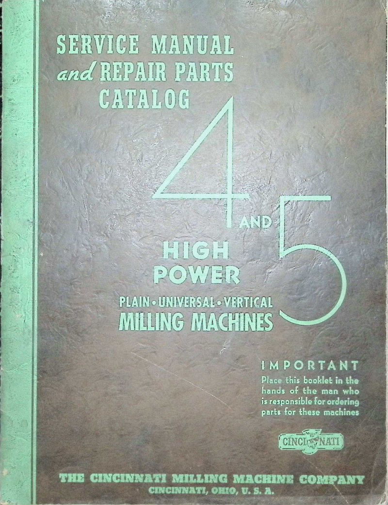
No. 4 & 5 High Power Milling Machines Service Manual
Service manual and repair parts catalog for Cincinnati No. 4 and 5 high power milling machines, covering plain, universal, and vertical models. This workshop manual provides detailed instructions for dismantling and reassembling units, nomenclature charts for identifying components, comprehensive parts lists, and step-by-step repair procedures essential for maintenance and restoration work. Published by The Cincinnati Milling Machine Company, Cincinnati, Ohio. Copyright 1938.
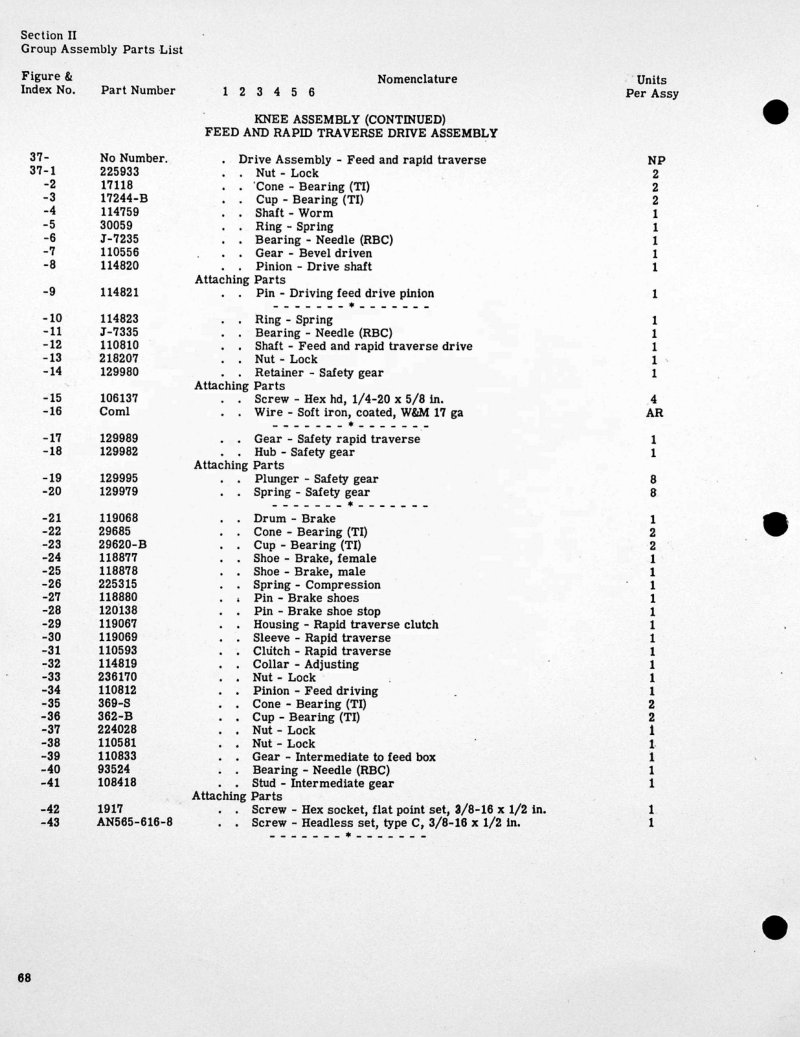
No. 4 Vertical High Power Dial Mill Parts List
Cincinnati No. 4 Vertical High Power Dial Mill parts list and exploded diagrams. Section II covers Group Assembly components, including the Knee Assembly with its Feed and Rapid Traverse Drive Assembly, plus the Knee Guide Assembly RH. Includes comprehensive parts nomenclature with part numbers, component designations, and quantities per assembly. Technical drawings illustrate component relationships and assembly integration, essential for identifying replacement parts, ordering spares, and understanding the machine's mechanical structure.
No. 4 Vertical High Power Dial Mill Parts List
Cincinnati No. 4 Vertical High Power Dial mill parts list and catalog covering repair parts identification for models 3, 4, 5, and 6 in both Dual and High Power Dial configurations. This parts catalog, publication M-1784, uses exploded view drawings and sectional cross-sections to illustrate the Universal Column and Saddle assemblies, making it straightforward to locate and order the exact replacement components you need. The 33 assembly groups documented include the gear shifter bracket, feed box assembly, head spindle unit, saddle structure, knee assemblies, and the various control linkage systems that operate the machine. Originally published in 1952, this reference remains essential for Cincinnati vertical milling machine maintenance and repair work.
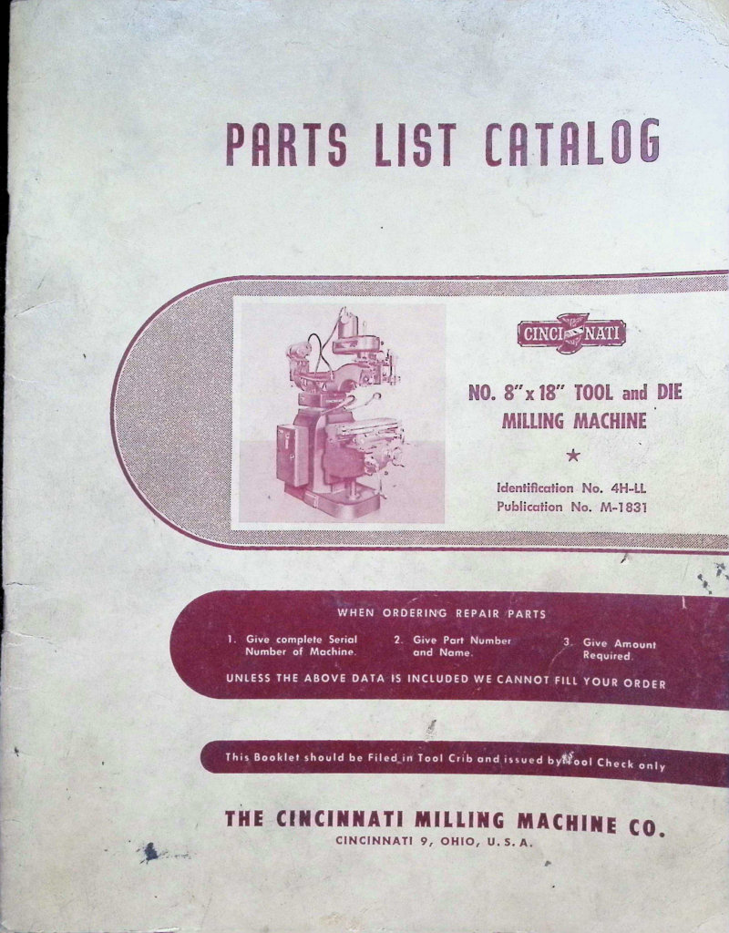
No. 8x18 Tool and Die Milling Machine Parts List
Parts list and service catalog for the Cincinnati No. 8×18 Model OM Tool and Die Milling Machine (Identification No. 4H-LL, Publication No. M-1831). This comprehensive workshop manual serves as an essential reference for technicians and operators needing detailed component information and assembly breakdowns. A complete key number index enables rapid part identification across all functional systems. Functional diagrams, dimensional diagrams, and a lubrication diagram clearly map the machine's internal layout and maintenance points. An imperial-to-metric conversion table supports international reference. Detailed parts lists cover all major assemblies: Hydraulic Automatic Depth Control (Unit 4HDR), Motor Drive (Unit 4HN), Spindle Carrier (Unit 4HV), Slotting Attachment (Unit 4HHF), Duplex Rotary Table (Unit 4HJG), Right and Left Attachment (Unit 4HHE), Protractor Template (Unit 4HHZ), Cross Template Bracket (Unit 4HEB), Saddle Table (Unit 4HH), Hand Pickfeed for Saddle (Unit 4HJA), Knee (Unit 4HK), Column (Unit 4HC), and Coolant Pump and Piping (Unit 4HP). A dedicated section on instruction plates provides mounted operator guidance. Essential for service technicians, maintenance personnel, and machine rebuilders sourcing components and verifying assembly configurations.
Nos. 1-12 & 1-18 Automatic Milling Machines Owner's Manual
Operator's instruction booklet for Cincinnati Nos. 1-12 and 1-18 Plain Automatic Milling Machines. Publication No. M-849-6, dated 1965. This workshop manual served as the primary reference for machine operators and was completely current at the time of publication, though design refinements may introduce minor variations from delivered units. Intended for shop-floor reference and tool-crib filing, this repair and maintenance guide covers the essential procedures for running and maintaining these automatic milling machines safely and efficiently.
Parts and Service Manual for Cincinnati Milacron 2, 3, 4
Parts and service manual for Cincinnati Milacron 2, 3, and 4 milling machines—plain, universal, and vertical dial types, model OM. This workshop manual covers safety precautions, personal safety guidelines, and work area considerations necessary for safe operation and maintenance of these industrial machines. Essential reference for technicians and operators performing repairs, preventive maintenance, and parts identification on Milacron equipment. Table of Contents: - Parts list catalog - This catalog to be used only for machines - Whose serial number begins with 2a or 4a - Page No. - Functional Diagrams - Dimensional Diagrams - Key Number Index - How To Order Repair Parts - Shifter Bracket (Unit No. 4AS) - Feed Box (Unit No. 4AF) - Pulley Bracket (Unit No. 4AJ) - Column (Unit No. 4AC) - Saddle Table (Unit No. 4AH) - Knee (Unit No. 4AK) - Motor Drive (Unit No. 4AN) - Coolant Pump and Piping (Unit No. 4AP) - Power Feed Worm Box (Unit No. 4AAJ) - Turret Stop and Stop Bracket (Unit Nos. 4AAR, 4AAK) - Hand Feed Worm Box (Unit No. 4AAK) - Table Hand Feed Attachment (Unit No. 4AAS) - Electrical Equipment (Unit Nos. 4AM, 4ANN) - Instruction Plates - PATENT NOTICE: The machines and attachments illustrated and described - in this book are protected by issued and pending United States and Foreign Patents. - The design and specifications of the machine and attachments illus - trated and described herein are subject to change without notice.
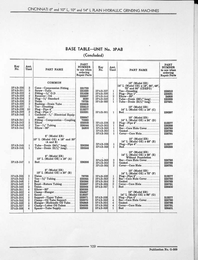
Plain Hydraulic Grinding Machines Parts List
Parts list and technical catalog for Cincinnati 6 and 10 L, 10 and 14 L plain hydraulic grinding machines. This comprehensive parts reference includes detailed identification of all major components with key numbers, part names, and OEM part numbers covering the base table unit (3PAB), wheel head unit (3PAW), and grinding wheel spindle assemblies. Exploded view diagrams clearly show component locations and how subassemblies fit together, making it straightforward to order the right replacement parts or understand the machine's construction. Essential reference for maintenance, repairs, and sourcing replacement components for these Cincinnati grinding machine models.
Plain Hydraulic Grinding Machines Service Manual
Service manual and parts list catalog for Cincinnati 6 inch and 10 inch L, 10 inch and 14 inch L plain hydraulic grinding machines (Model ER and Model OE). This workshop manual covers adjustment procedures for table operating pistons, servo infeed attachment, footstock spindle, grinding wheel spindle bearings and thrust bearing, V-belt drives, headstock motor and spindle systems, hydraulic oil pressure settings, and electrical pressure switch configurations. Includes dimensional drawings, floor plans with leveling instructions for 72 inch and 96 inch grinders, cross feed handwheel mechanisms, operating controls, lubrication system schematics, and complete hydraulic circuit diagrams with servo control logic. Features a conversion chart for inches to millimeters. Essential repair and maintenance reference for operators and technicians working with Cincinnati precision grinding equipment. Publication No. G-569, Identification No. 3P-0M. Table of Contents: - SERVICE MANUAL - ADJUSTMENTS - To Adjust Alignment of Table Operating Pistons - Automatic and Hand Servo Infeed Attachment - Footstock Spindle - Grinding Wheel Spindle Bearings - Grinding Wheel Spindle Thrust Bearing - Grinding Wheel Spindle V-Belt Drive - Grinding Wheel Speed Safety Device - Headstock Motor Drive V-Belts - Headstock Motor Unibrake—6" and 10" L Grinders only - Headstock Spindle Drive Chain—6" and 10" L Grinders - Headstock Spindle Drive V-Belts—10" and 14" L Grinders - Hydraulic Oil Pressure - Volume of Oil to Table Ways - Setting of Hydraulic Infeed and Spindle Oil Electrical Pressure Switches - CONVERSION CHART (Inches to Millimeters) - DIAGRAMS AND ILLUSTRATIONS - 6" and 10" L Plain Hydraulic Grinders - Dimensional Drawing - Left Rear View - Right Front View - Right Rear View - 10" and 14" L Plain Hydraulic Grinders - Dimensional Drawing - Floor Plan and Leveling Instructions for 10" and 14" L x 72" Grinder - Floor Plan and Leveling Instructions for 10" and 14" L x 96" Grinders - Left Front View - Left Rear View - Right Rear View - 6" and 10" L, 10" and 14" L Plain Hydraulic Grinders - Cross Feed Handwheel and Pickfeed Mechanism - Operating Control Knobs and Lever - Schematic Layout of Table Ways Lubrication System - Hydraulic Circuits - Table Circuit with Servo Control - Explanation
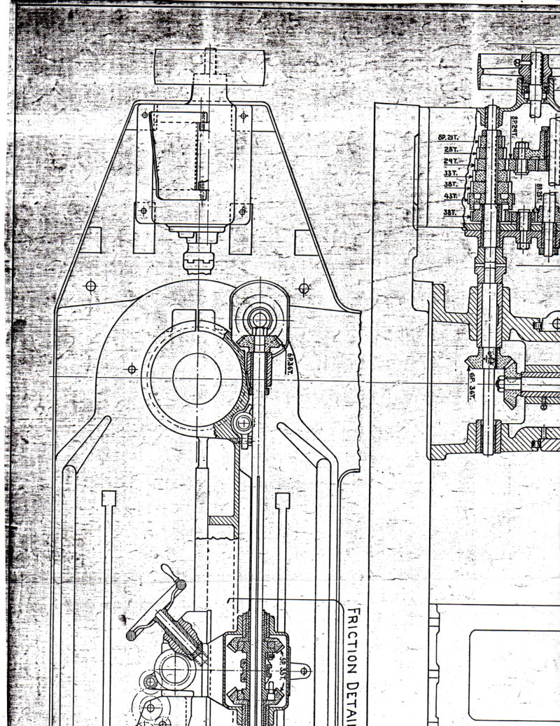
Plain Radial Drill Repair Parts Drawing
Technical drawing and parts documentation for Cincinnati plain radial drill machines in 4 and 4.5 foot configurations. This repair parts drawing provides detailed mechanical illustrations of the drill assembly, friction mechanism, back gearing system, and feed gearing components, including cross-sectional views and assembly details essential for maintenance and repair work on these industrial drilling machines.
PWM Drive Controller 6RB20 Technical Manual
Complete technical manual for the Cincinnati Milacron PWM Drive Controller Model 6RB20 (2B), manufactured by Siemens AG. This service manual covers Cincinnati part numbers 1-230-0450 through 0479 and serves as the definitive workshop reference for technicians maintaining this industrial drive controller. Publication 7-000-0493MA, issued April 1, 1984 and revised May 1, 1984. Spanning 151 pages, this manual contains detailed technical specifications, operating instructions, troubleshooting procedures, and essential safety precautions for maintenance and field service of the PWM drive system. Table of Contents: - This page does not contain a table of contents. It is the title/cover page of the technical manual.
Recommendations for Sharpening Carbide Milling Cutters
Technical service guide from Cincinnati Milling Machine Co. detailing carbide milling cutter sharpening procedures and best practices. Covers carbide grinding department setup and workflow, operator qualifications and safety requirements, and proven sharpening techniques for maintaining cutter performance. Features detailed illustrations and specifications for Cincinnati No. 2 Cutter and Tool Grinder equipment, making this an essential workshop reference for toolroom technicians and machine operators responsible for cutter maintenance and reconditioning.
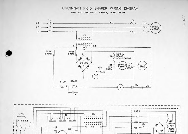
Rigid Shaper Wiring Schematic
Wiring schematic for the Cincinnati Rigid Shaper detailing the complete three-phase electrical configuration. This service manual covers the drive motor circuit with overload protection (OL), brake and clutch magnet circuits rated at 600V 0.25 MFD, control panel wiring layout, and rectifier unit connections. Includes dual power distribution schematics for 110V AC and 90V DC circuits, with color-coded wiring standards throughout for accurate troubleshooting and maintenance. Features the un-fused disconnect switch configuration typical of industrial shapers from this era.
Series 4 FT Horizontal Boring Machine Manual
Operation and maintenance manual for the Cincinnati Series 4 FT horizontal boring machine, Serial No. 4F-63, S.O. # A-3349-FT. Published by AMB Industries, Inc., Oak Creek, Wisconsin. This workshop manual provides comprehensive guidance on safe operation, routine maintenance, and proper care of this table-type horizontal boring, drilling, and milling machine for industrial metalworking. Includes a dedicated safety precautions section covering critical procedures before startup and during machine operation. Essential reference for operators and maintenance technicians responsible for this equipment. Table of Contents: - Safety Precautions - Section I — INTRODUCTION AND DESCRIPTION - 1.1 GENERAL INFORMATION - 1.2 MANUAL SCOPE - 1.3 NOTES, CAUTIONS AND WARNINGS - 1.4 GENERAL DESCRIPTION - 1.5 MAJOR MACHINE COMPONENTS - 1.6 AUXILIARY COMPONENTS - 1.7 IDENTIFICATION AND DATA PLATES - 1.8 RELATED PUBLICATIONS - Section II — UNPACKING, INSTALLATION AND PREPARATION FOR OPERATION - 2.1 GENERAL - 2.2 SPECIAL TOOLS - 2.3 CUSTOMER FURNISHED MATERIALS FOR INSTALLATION - 2.4 DISASSEMBLY PRIOR TO SHIPMENT - 2.5 RECEIVING INSPECTION - 2.6 FOUNDATION REQUIREMENTS - 2.7 INSTALLATION SAFETY PRECAUTIONS - 2.8 INSTALLATION PRECAUTIONS - 2.9 INSTALLATION PRECAUTIONS - 2.10 DETAILED INSTALLATION PROCEDURES - 2.11 LEVEL AND ALIGNMENT CHECK - Section III — OPERATING INSTRUCTIONS - 3.1 GENERAL - 3.2 OPERATING CONTROLS - 3.3 OPERATING NOTES - Section IV — PERIODIC MAINTENANCE - 4.1 GENERAL - 4.2 PERIODIC INSPECTIONS - 4.3 LUBRICATION - 4.4 PERIODIC INSPECTION AND LUBRICATION NOTES - Section V — GENERAL MAINTENANCE - 5.1 GENERAL - 5.2 HYDRAULIC SYSTEM - 5.3 ELECTRICAL TROUBLESHOOTING NOTES - 5.4 TROUBLESHOOTING - 5.5 LIMIT SWITCH ADJUSTMENT - 5.6 FERRAND INDUCTOSYN SYSTEM
Siemens DC Slide Drive Service Manual
Service manual for the Siemens DC slide drive unit model 6PB 2030-2DA00 used on CINCINNATI CINTURN Series 1208, 1210 and 1212 turning centers equipped with ACRAMATIC 850TC control. This workshop manual covers fine-tuning procedures, servo system adjustments, calibration steps, and detailed component specifications for field replacement of circuit boards and drive modules. Includes troubleshooting guidance for DC drive operation and maintenance of the slide mechanism. Publication No. 3-TC-84350, Part No. 3359036.
Spiropoint Drill Sharpener LM - Operating Manual
Operating manual and service guide for the Cincinnati Spiropoint drill sharpener, covering Model LM Series 500, 750 and 1000 machines. This workshop manual details the precision spiral point drill grinding machine's design and operation, including setup, adjustment, and maintenance procedures. Covers key functional components such as clearance angle adjustment mechanisms, drill diameter control systems, cylinder grinding wheel specifications, truing device operation, and mist coolant system management. Features detailed component descriptions with labeled technical diagrams throughout. Essential reference for operators and technicians performing routine maintenance, troubleshooting, and precision grinding operations on spiral point drills.
Super Service Radial Drill Instruction Manual
Comprehensive instruction manual and parts catalog for Cincinnati Bickford Super Service Radial Drills, covering models with 11, 13, 15, 17, and 19 inch diameter columns. This workshop manual provides detailed guidance on setup, operation, and maintenance essential for keeping these industrial drilling machines in reliable working condition. Covers proper machine installation, routine care procedures, lubrication schedules, and built-in accident prevention features. An invaluable reference for machine operators, maintenance technicians, and shop supervisors responsible for radial drill performance and safety.
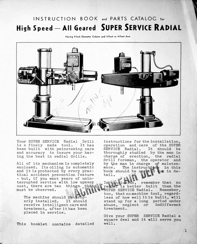
Super Service Radial Drill Instruction Manual
Comprehensive instruction manual and parts catalog for the Cincinnati Bickford High Speed All Geared Super Service Radial Drill, covering both 3-foot and 4-foot arm configurations with a 9-inch diameter column. This workshop manual provides essential setup and maintenance guidance for operators and technicians. Includes detailed erection instructions with precise hoisting weights—4,900 lbs for the 3-foot arm model and 5,300 lbs for the 4-foot arm model—ensuring safe installation and handling. Foundation requirements are fully specified with bolt spacing dimensions to guarantee proper machine leveling and stability. The manual addresses critical unloading precautions and mechanical setup procedures necessary for correct operation. Published by Cincinnati Bickford Tool Company as booklet R-23, this service documentation remains the authoritative reference for installation, adjustment, and parts identification on these precision radial drilling machines.
Super Service Radial Drill Service Manual
Comprehensive service manual and parts catalog for the Cincinnati Bickford Tool Company High Speed All Geared Super Service Radial drill. This workshop manual covers the 9-inch column radial drill system available with 3-foot or 4-foot arm configurations, with hoisting specifications of 4,900 lbs and 5,300 lbs respectively. Includes detailed sections on machine erection, unloading procedures, and foundation installation to ensure proper setup. Provides essential maintenance instructions, operational care guidance, and handling procedures necessary for safe and efficient operation of this industrial drilling equipment. Designed as a technical reference for technicians performing routine maintenance, troubleshooting, and parts identification on the Cincinnati radial drill platform.
Super Service Radial Drills Service Manual
Comprehensive service manual for Cincinnati Bickford Super Service Radial Drills, covering models with 11, 13, 15, 17, and 19 inch diameter columns. This workshop manual provides essential technical guidance on equipment unloading, foundation preparation and installation, and operational procedures for safe and efficient machine setup. Includes critical hoisting weights for different arm and column assemblies, ensuring proper handling during installation and relocation. Detailed setup instructions walk through the complete commissioning process, making this repair manual indispensable for maintenance technicians and shop managers responsible for these industrial drilling machines.
Super Service Radials Service Manual
Instruction book and parts catalog for Cincinnati Super Service Radial Drills with 13, 15, 17 and 19 inch diameter columns. Published by The Cincinnati Bickford Tool Co. in 1930. This service manual covers installation, operation and maintenance of radial drill machines, including machine setup, routine care procedures and best practices for equipment longevity. Includes comprehensive parts list and technical specifications.
Super-Service Upright Drills Parts List
Comprehensive parts list for Cincinnati Bickford Super-Service geared upright drills covering all standard models in 21 inch, 24 inch, and 28 inch configurations with both round and box column designs. This repair parts manual provides the parts catalog reference U-23-B from The Cincinnati Bickford Tool Co., Oakley, Cincinnati, Ohio, enabling technicians and operators to source exact replacement components for maintenance and repair work on these industrial drilling machines.
Super-Service Upright Drills Parts List U-23
Parts list for Cincinnati-Bickford Super-Service Upright Drills, covering 21", 24" and 28" models in both round and box column configurations. This repair manual provides illustrated parts diagrams and complete part numbering across all major assemblies: spindle systems, feed mechanisms, gearing arrangements, tables, columns, and structural framework. Detailed sections cover the initial drive, feed change gearing, and speed change gearing—essential reference for technicians servicing these precision drilling machines. Includes comprehensive identification of every replaceable component.
Toolmaster Milling Machine Service Manual
Service manual and parts list for Cincinnati Milacron Toolmaster milling machines (Publication M-2318-3). This workshop manual covers comprehensive safety precautions, operating guidelines, and operational warnings essential for safe machine operation. The manual emphasizes reading all safety instructions before use and notes that protective devices are shown in open or removed positions throughout for instructional clarity. Includes maintenance procedures and parts identification for technicians and machine operators. Table of Contents: - ADJUSTMENTS - To Adjust Arbor Support Bushing - To Adjust Backlash Eliminator - To Adjust Drive Belts: Style 1-B - To Adjust Drive Belt: Style 1-E - To Adjust Gibs - To Adjust Quill Powerfeed Clutch: Style 1-B - To Adjust Shaping Attachment Drive Belt - To Adjust Shaping Attachment Gib - CONVERSION CHART (Inches to M/M) - DIMENSIONAL DRAWINGS - DISMANTLING INSTRUCTIONS - To Remove V-Belt Housing: Style 1-B - To Remove V-Belt Housing: Style 1-D - To Remove V-Belt Housing: Style 1-E - To Remove Splined Spindle Assembly: Style 1-B - To Remove Drive Spindle Assembly: Style 1-B - To Remove Drive Spindle Assembly: Styles 1-D, 1-E - To Remove Spindle Housing with Spindle: Style 1-B - To Remove Spindle Housing with Spindle: Styles 1-D, 1-E - To Remove Spiral Gear Shaft: Style 1-B - To Remove Transmission Shaft: Style 1-B - To Remove Speed Change Assembly: Style 1-D - To Remove and Dismantle Powerfeed Housing: Styles 1-D, 1-E - To Remove Overarm and Turret: Styles 1-B, 1-D, 1-E - To Remove Overarm (Heavy Duty): Styles 1-C, H-V - To Remove and Dismantle Overarm Gear Housing: Styles 1-C, H-V - To Remove Spindle Housing and Drive — Without Hand Feed: Styles 1-C, H-V - To Remove Spindle Housing and Drive — With Hand Feed: Styles 1-C, H-V - To Remove and Dismantle Intermediate Swivel Housing: Styles 1-C, H-V - To Remove Table - To Remove Table Leadscrew - To Remove Table Powerfeed Housing - To Dismantle Table Powerfeed Housing
Toolmaster Milling Machines Operator's Manual
Operator's instruction manual for Cincinnati Toolmaster milling machines, publication M-1941-1 from 1956. This workshop guide covers essential operational procedures and machine setup techniques for shop floor use. Originally designed for tool crib distribution and reference, the manual provides straightforward guidance on running these mid-century precision milling machines safely and effectively.
Tray-Top Engine & Tool Room Lathes Service
Operating, Parts and Service Manual for Cincinnati Tray-Top Engine & Tool Room Lathes (10-in., 12.5-in., 15-in. and 18-in. models) and 15" & 18" Fixed Gap Bed Lathes. Publication No. T-107-3. Original manual reprinted with addition of Safety Precautions. Covers operation, parts identification, and service procedures. Includes patent notices and safety guidelines per OSHA standards. Table of Contents: - DESCRIPTION - SPECIAL SERVICE TOOLS - OPERATION - INSPECTION AND LUBRICATION - MAINTENANCE - PARTS LIST
VerciPower Milling Machines Operator's Manual
Operator's manual for Cincinnati VerciPower milling machines, publication M-2571. This workshop guide covers essential operation and maintenance procedures for VerciPower models, including setup, control operation, and routine upkeep. Features detailed illustration references, patent documentation, and serial number identification information. Issued by The Cincinnati Milling Machine Co., Milling Machine Division, Cincinnati, Ohio 45209. Copyright 1964. An authoritative reference document for machinists and shop personnel responsible for daily operation and care of these precision milling systems. Table of Contents: - Standard Equipment - Machine Specifications - Horizontal Machines - Vertical Machines - Installation Instructions - Foundation - Lifting - Leveling - Bolting the Machine to the Foundation - Assembling the Table - Assembling Counterweight - Starting Machine for the First Time - Lubricationsn - Lubrication Diagram - Lubrication Instructions - Operating Instructions - Functional Diagrams - Starting the Machine - Changing Spindle Speeds - Micrometer Dials - Hand Table Feed - Hand Cross Feed - Hand Vertical Feed - Power Feed Controls - Power Table Feed - Power Cross Feed - Power Vertical Feed - Feeds - Changing Feeds - Power Rapid Traverse - Rear Hand Controls - Rear Power Feed Controls - Operating Instructions (Vertical Machine) - Hand Feed to Vertical Spindle Carrier - Power Feed to Vertical Spindle Carrier - Power Rapid Traverse to Vertical Spindle Carrier - Clamping the Spindle Carrier in Position - Four-Position Turret Stop and Dial Indicator - Rear Controls - Setting Up the Machine - Overarm and Arbor Supports