
TEPPAZ - Service Manuals
19 manuals available for download
TEPPAZ is a legendary French manufacturer of vintage electrophones and radios, renowned for their distinctive design and reliable audio engineering from the mid-20th century. Our comprehensive collection includes original service manuals, repair guides, and technical documentation available as instant PDF downloads, providing technicians and enthusiasts with the schematics, troubleshooting guides, and parts lists needed to restore and maintain these classic audio devices. Whether you're seeking detailed workshop manuals for a specific model or owner's documentation for maintenance and repair, our curated catalog ensures you have access to authentic factory materials for proper servicing and preservation of TEPPAZ audio equipment.
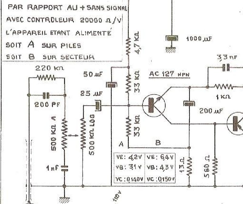
TEPPAZ B146 Electrophone Bi-Balad Electronic Schematic
Electronic schematic diagram for the TEPPAZ B146 Bi-Balad turntable showing complete circuit topology, including transistor types (AC127, AC128, AC125, AC12B), output transformer (TA7773), power supply design, amplifier stage configuration, and speaker wiring. Voltage measurements and component specifications are marked throughout. Essential for troubleshooting, alignment, and maintenance of the B146 electrophone. Document dated 15.11.67.
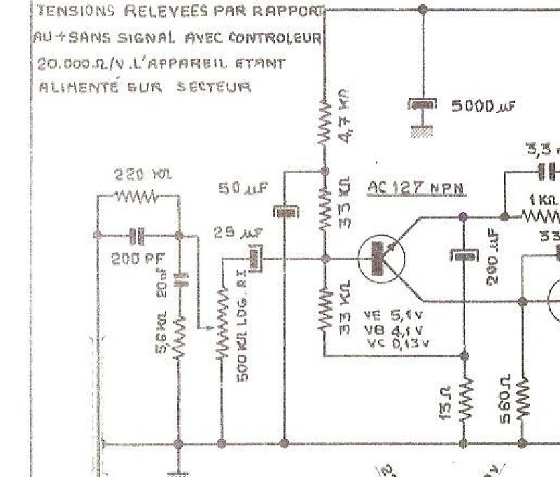
TEPPAZ CLEO Electrophone Electronic Schematic
Electronic schematic diagram for the TEPPAZ CLEO electrophone, serving as an essential technical reference for troubleshooting and repair of this vintage solid-state amplifier system. The schematic documents voltage measurements at critical test points throughout the circuitry, transistor stage configurations using AC127 NPN, AC125, and AC128 discrete components, and the complete passive component network of capacitors and resistors that shape signal response. Also shown is the power transformer with integrated commutator switching circuit, along with the motor drive section and automatic stop mechanism that controls record playback. This schematic provides the foundation for diagnosing signal path faults, verifying bias and operating voltages, and understanding the automatic shutoff sequence integral to the turntable's operation.
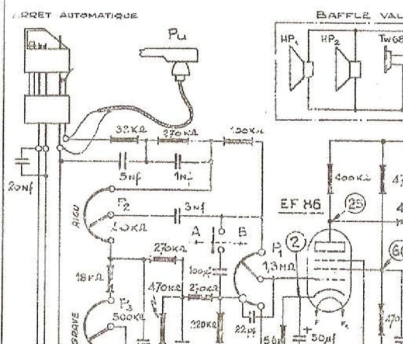
TEPPAZ Electrophone 336 - Electrical Schematic 2
Electrical schematic diagram for the TEPPAZ Electrophone 336, detailing the complete circuit topology with vacuum tubes, resistors, capacitors, transformers, and signal routing throughout the amplifier. Covers the damping valve circuit, phono input selector, tone control network, and output stage configuration. An essential technical reference for service work, circuit troubleshooting, and understanding the signal path in this classic tube-based turntable amplifier system.
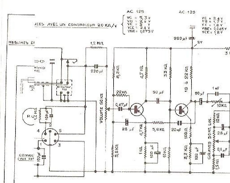
TEPPAZ Electrophone 432 Electronic Schematic
Electronic schematic diagram for the TEPPAZ Electrophone 432 turntable, providing the complete circuit layout essential for service and repair work. The diagram details all tube amplifier stages, AC power supply sections (AC 125, AC 126, AC 128, 2x AD 162), transformer networks with precise component values, and the full output stage configuration. Includes the 4-diode bridge rectification circuit for power supply, pickup connector arrangement, and magnetic cartridge signal path. All capacitor and resistor values are specified throughout. Technical drawing dated 94-8-86. This workshop-level schematic is indispensable for troubleshooting, maintenance, and restoration of the Electrophone 432 tube turntable amplifier system.
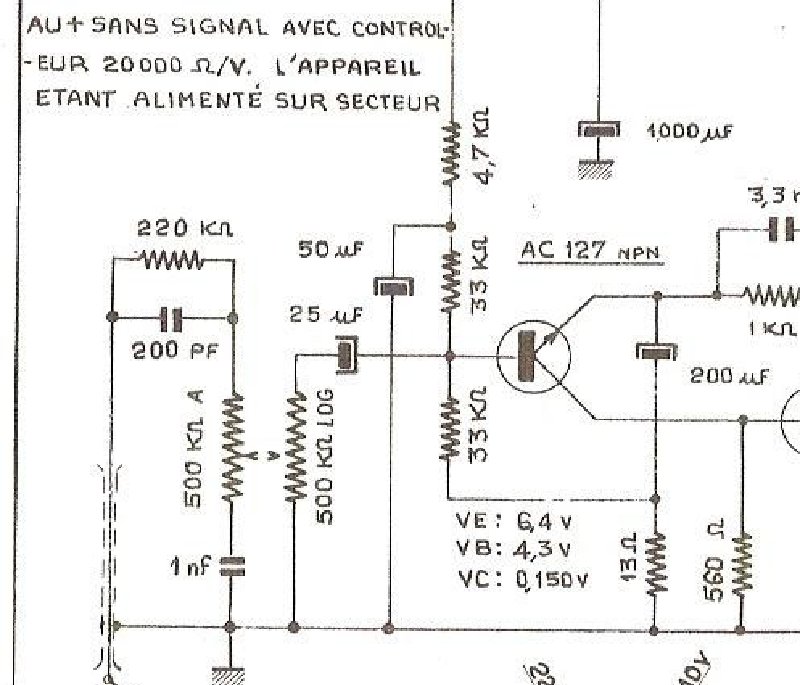
TEPPAZ Electrophone Balad - Schematic Diagram 2
Schematic diagram for the TEPPAZ Electrophone Balad portable record player, detailing the complete audio amplifier circuit architecture. Maps the dual-transistor design using AC127 and AC128 transistors, power supply regulation stage, output transformer configuration, and speaker termination. Includes annotated voltage measurements and component values throughout—essential reference for troubleshooting, repair work, and understanding the signal path in this classic portable turntable. Invaluable for service technicians and restoration enthusiasts working on vintage TEPPAZ portables.
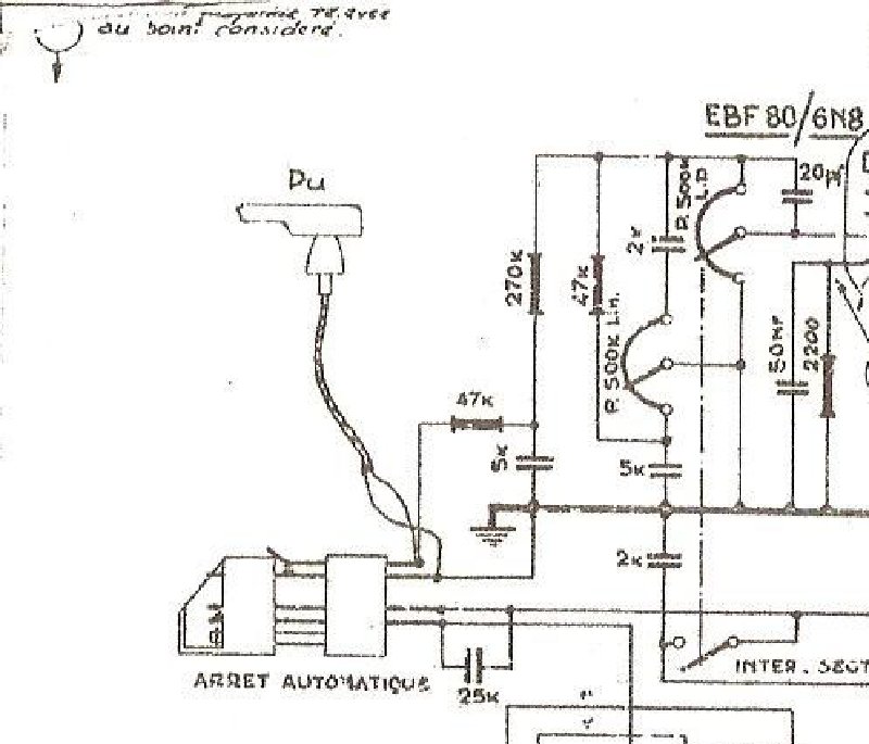
TEPPAZ Electrophone Presence - Electronic Schematic
Electronic schematic diagram for the TEPPAZ Electrophone Presence record player. This schematic is essential for service technicians to understand the vacuum tube amplifier architecture, troubleshoot electrical faults, and perform maintenance and component replacement. It illustrates the complete circuit topology, including the EBF80/6N8, E84/6BQ3, and EZ80/6V4 vacuum tubes, power transformer specifications, motor control circuit, automatic stop mechanism, inter-secteur selector switch for dual mains voltage operation, and 50 Hz AC power supply connections. The diagram clarifies signal flow from the turntable motor through the amplification stage to speaker output, making it an indispensable reference for electrical diagnostics and repair work on the Presence model.
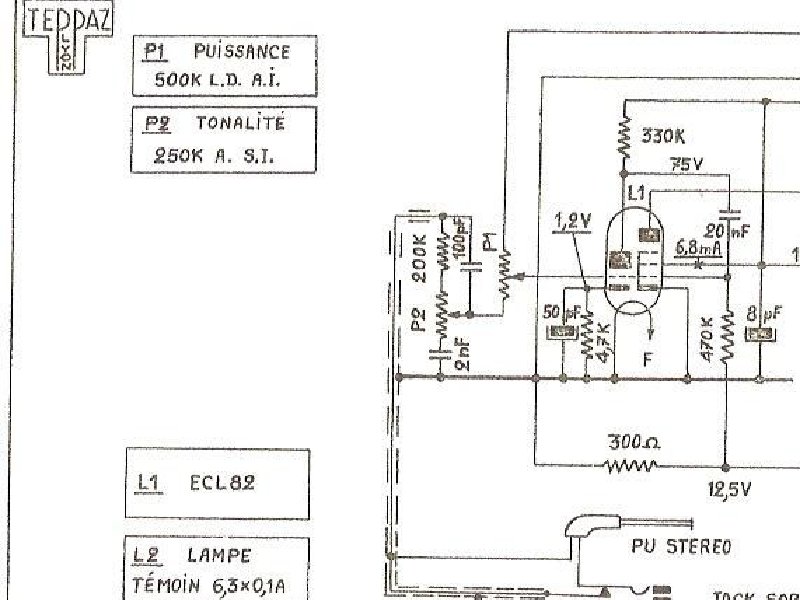
TEPPAZ Electrophone Senior Electronic Schematic
Electronic schematic diagram for the TEPPAZ Electrophone Senior turntable, presenting the complete circuit topology of this vintage tube-based phonograph amplifier. Documents the ECL82 output tube configuration, power transformer specifications, audio amplification and tone control stages, motor control circuitry with automatic shutoff function, and dual-channel stereo output connections. Includes transformer options for 127V/220V and 220V/250V mains operation. Essential reference for technicians servicing or restoring this model, enabling diagnosis and repair of audio circuit faults, amplifier stage issues, and power supply problems.
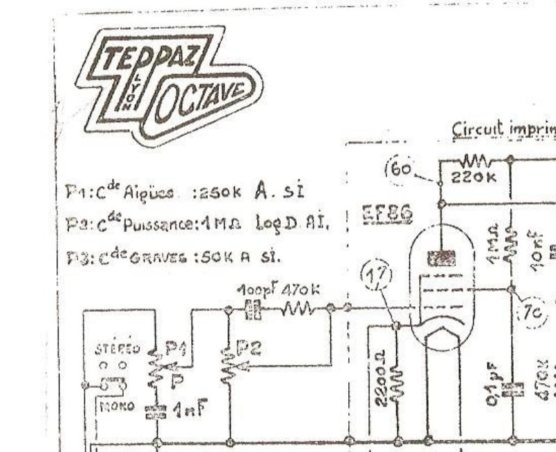
TEPPAZ Lyon Octave - Schematic Diagram 2
Electronic schematic diagram for the TEPPAZ Lyon Octave audio amplifier. Details the complete circuit topology with vacuum tubes EL86, EL84, and TS27, including power supply design, output and power transformers, coupling and filtering capacitors, load resistors, and speaker output configuration. Essential reference for servicing, troubleshooting, and maintaining this tube amplifier model, supporting repair work, circuit analysis, and component replacement procedures.
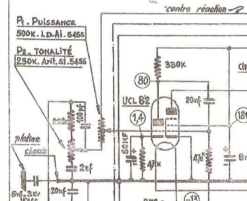
TEPPAZ Lyon Oscar Electronic Schematic Diagram
Electronic schematic diagram for the TEPPAZ Lyon Oscar tube radio receiver. Provides complete circuit layout showing tube configurations, transformer design, capacitor networks, and resistor values throughout the signal path. Specifies dual operating voltage capability at 127V and 220V AC, essential for understanding the power supply architecture and adapting setup to different regional electrical standards. Includes detailed documentation of the motor mechanism and automatic stop circuit controlling the receiver's mechanical functions. Indispensable for servicing or restoring this classic radio, offering the technical precision required for component-level troubleshooting and restoration work.
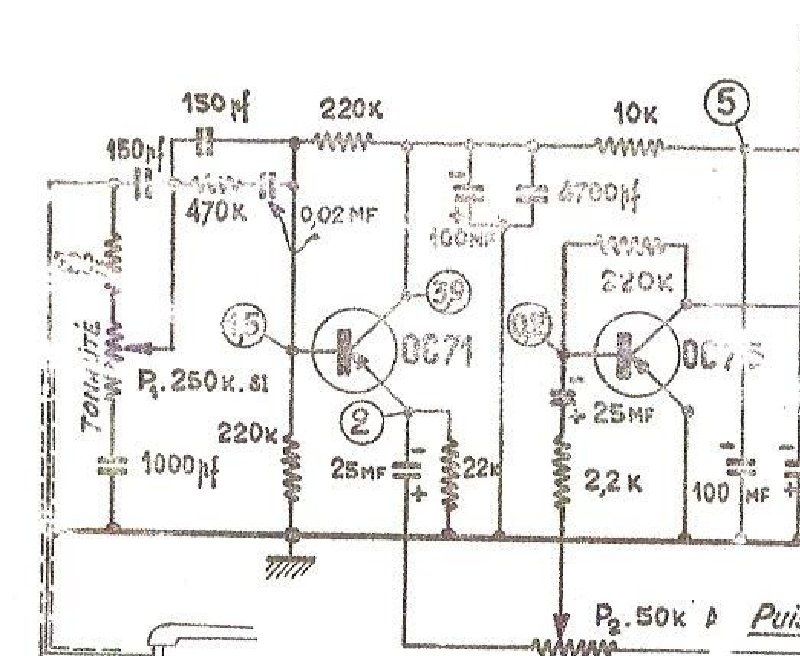
Teppaz Lyon Transit - Electrical Schematic
Electrical schematic diagram for the Teppaz Lyon Transit radio receiver. This detailed circuit layout illustrates the complete tube-based architecture, including the power supply section, RF and IF amplification stages built around OC71 and OC74 transistors, output transformer, and all associated passive components. The schematic also documents the modulation circuit featuring a 50 kOhm potentiometer and self-excited coil arrangement. An essential service manual resource for technicians and radio repair specialists working on this vintage receiver model, providing the technical reference needed for troubleshooting, maintenance, and component-level repair.
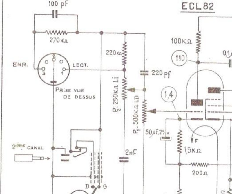
TEPPAZ Oscar Major ECL82 Electronic Schematic
Electronic schematic diagram for the TEPPAZ Oscar Major model ECL82, a tube-based amplifier. The schematic shows the ECL82 output tube configuration, T.7890 and T.7878 output transformers, dual 50µF electrolytic capacitors, and supporting resistor and capacitor networks throughout the signal path. A distributor section and automatic shutdown circuit ensure safe operation. Measurement specifications and operating points are provided for both 120V and 234V AC input configurations, making this essential reference for technicians performing alignment, troubleshooting, and component-level repair on vintage valve amplifiers.
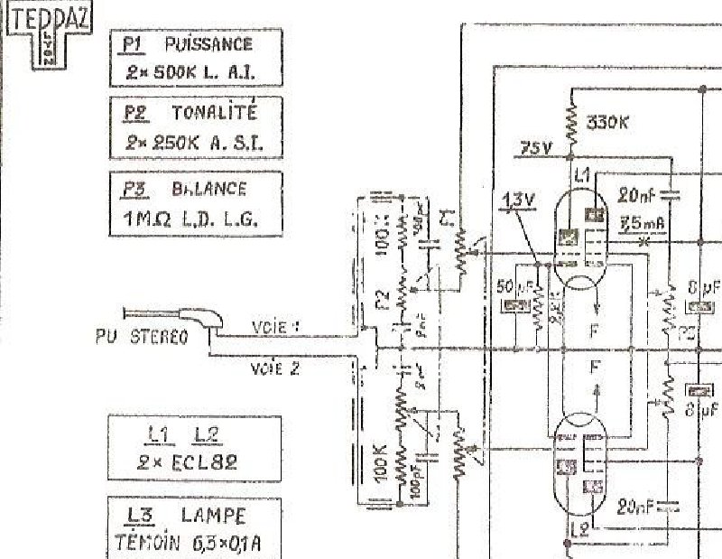
TEPPAZ Oscar Stereolux Electrophone - Electronic Schematic
Electronic schematic diagram for the TEPPAZ Oscar Stereolux electrophone model 6160. This service manual details the complete tube-based audio amplifier circuits, including multiple transformers, dual output stages (BAFFLE 1 and BAFFLE 2), and full power supply schematics for both 250V and 220V configurations. Also covers the motor control section with automatic stop mechanism, component values, and all interconnections required for troubleshooting and repair of this classic tube amplifier turntable system.
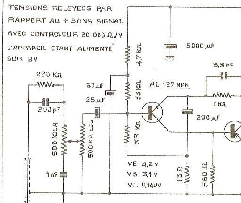
TEPPAZ Pil Balad Electrophone Electronic Schematic
Electronic schematic diagram for the TEPPAZ Pil Balad electrophone model 8147A. This service manual documents a transistor-based audio amplifier circuit built around AC127 and AC125 transistors, with voltage measurements (VE, VB, VC) marked at critical test points throughout. The schematic shows coupling capacitors, output transformer design, 5-ohm speaker impedance, automatic shutdown circuitry with motor control (M), and 9V power supply configuration. Voltage reference readings enable precise troubleshooting and circuit analysis. Essential for technicians servicing, repairing, or analyzing this classic electrophone model.
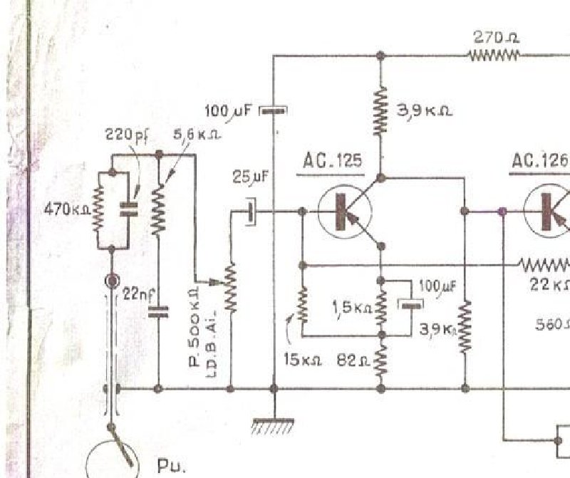
TEPPAZ Pirouett Electrophone - Schematic Diagram 2
Electronic schematic diagram for the TEPPAZ Pirouett electrophone. Details the complete circuit layout including AC.125 tubes in the signal path, resistors, capacitors, and transformers throughout the amplification stages. The output stage uses AC.128 tubes driving the loudspeaker. Includes the automatic stop circuit and motor control circuit, both powered from a 9V battery supply. Essential reference for troubleshooting, repair, and understanding the audio electronics of this portable record player.
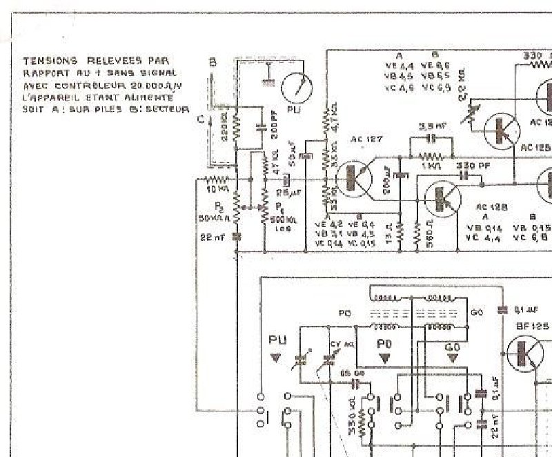
TEPPAZ Radio BALAD Electronic Schematic
Complete electronic schematic for the TEPPAZ Radio BALAD model N° 8458. This service documentation provides the full circuit diagram layout, detailing vacuum tube configurations (PL and AC tubes), transformer windings and connections, capacitor and resistor networks throughout the signal path, magnetophone input circuitry, and the automatic stop mechanism with relay switching logic. Essential reference for technicians troubleshooting or restoring this vintage radio receiver.
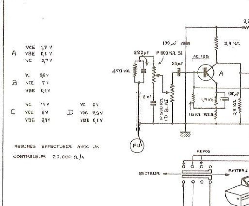
TEPPAZ Tourist Major Electrophone Schematic
Electronic schematic diagram for the TEPPAZ Tourist Major electrophone model 7399. This service manual covers the complete amplifier circuit topology, including the preamplifier stage with AC125/AC126 transistors, the output stage with AC128 transistors, and the power supply section with transformer specifications. The schematic also documents the anti-parasitic circuit and motor-driven mechanism, essential for understanding the turntable's noise suppression and mechanical operation. A straightforward reference for technicians working on vintage record player repairs and maintenance.
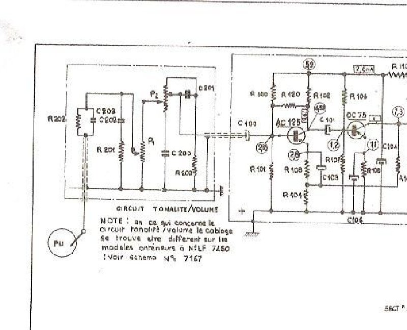
TEPPAZ Tourist Turntable - Circuit BF Schematic
Electronic schematic diagram for the BF (low-frequency) circuit section of the TEPPAZ Tourist turntable, a mid-century record player manufactured by TEPPAZ SA in Lyon. This technical drawing shows the complete component layout—resistors, capacitors, transformers, and vacuum tubes—that comprise the audio amplification stage. Essential reference for servicing or restoring this classic turntable model. Single-page schematic.
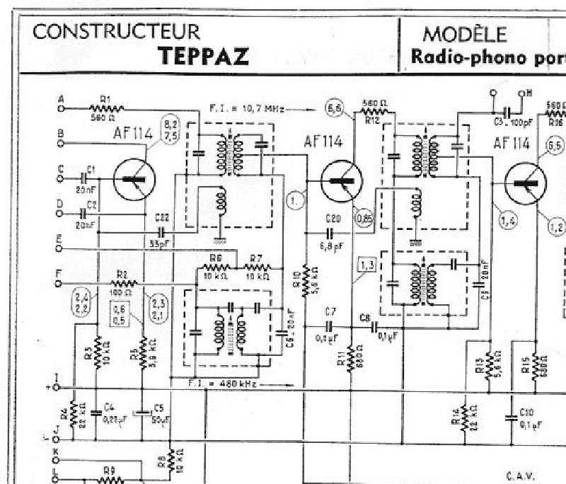
TEPPAZ Transitradio Portable Radio-Phono Electronic Schematic 1963
Electronic schematic diagram for the TEPPAZ Transitradio portable radio-phonograph model 1068 from 1963. This service documentation presents the complete circuit layout with vacuum tubes (AF114, OA79), transformers, capacitors, resistors, and tone control circuitry. Detailed technical views include the tone correction system (Fig. 4) and FM detector plate circuit (Fig. 5). An essential reference for understanding the internal design and repair of this classic French portable radio-phono unit.

Turntable Teppaz Transit - Electronic Schematic
Complete electronic schematic for the TEPPAZ Transit turntable amplifier system. This technical documentation provides the precise circuit architecture needed by technicians undertaking repair, restoration, or maintenance work. The input stage is fully documented, showing coupling capacitors (150 µF, 1000 µF), biasing resistors (220 kΩ, 470 kΩ, 10 kΩ), and the preamplifier section built around 0C70 and 0C78 tubes. The main power amplification section features dual output stages with 0C74 tubes, output transformer, and automatic shutdown circuitry clearly traced. Power supply architecture includes the 500 µF reservoir capacitor and dedicated bias circuits. A separate section details the turntable motor circuit with clutch mechanism, variable power adjustment incorporating temperature compensation, and coupling capacitors (4700 µF). All critical component values are clearly specified—load resistances (630 Ω, 4.7 kΩ, 56 Ω), filter capacitors, and coupling capacitors—providing the exact reference data needed for accurate circuit analysis, troubleshooting, and component replacement.