SCOTT - Service Manuals
43 manuals available for download
SCOTT is a legendary name in vintage audio and high-fidelity equipment, renowned for precision-engineered amplifiers, preamplifiers, and signal processing components that defined professional sound reproduction. Our comprehensive collection of 43 SCOTT technical documents—including detailed service manuals, repair guides, schematic diagrams, and workshop materials—provides technicians, enthusiasts, and restorers with the essential resources needed for maintenance, troubleshooting, and accurate alignment of these classic audio systems. Whether you require an owner's manual for reference, a parts list for sourcing components, or in-depth technical schematics and test procedures, our PDF downloads deliver authentic factory documentation that ensures proper servicing and preservation of SCOTT equipment's legendary performance standards.
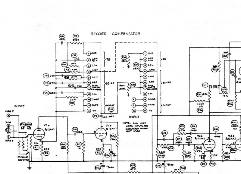
210-D Dynaural Amplifier Schematic
Complete electrical schematic diagram for the Scott 210-D Dynaural Amplifier — an essential service resource for technicians and enthusiasts restoring this classic tube amplifier. The schematic presents the full circuit architecture including the input stage, record compensator, dynamic range control circuit, bass and treble tone control sections, record monitor circuit, power output stage with tube complement, speaker connection topology, and complete power supply design. Component identification and interconnection routing are clearly marked throughout, enabling detailed troubleshooting, repair, and restoration work on this vintage audio component.
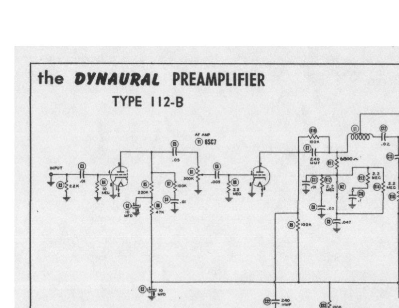
Dynaural Type 112-B Preamplifier Schematic Diagram
Complete electronic schematic diagram for the Scott Dynaural Type 112-B preamplifier, a tube-based audio design. The diagram traces the full signal path from input through treble and bass gate circuits to the output stage, with all component values clearly marked and tube type designations (6SJ7). Two reference tables at the bottom consolidate tube specifications and component data for quick lookup during repair or restoration work. Essential reference material for anyone servicing or restoring this classic preamp.
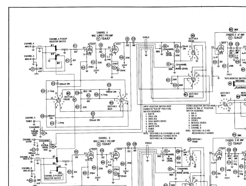
H. H. Scott Model 130 Schematic Diagram
Complete electronic schematic diagram for the H. H. Scott Model 130 amplifier. This single-page technical drawing maps the tube-based circuit topology with all channels, discrete components, and interconnecting wiring paths. Includes component reference designators and operating voltage specifications—essential for troubleshooting, repair, or restoration of vintage Scott audio equipment.
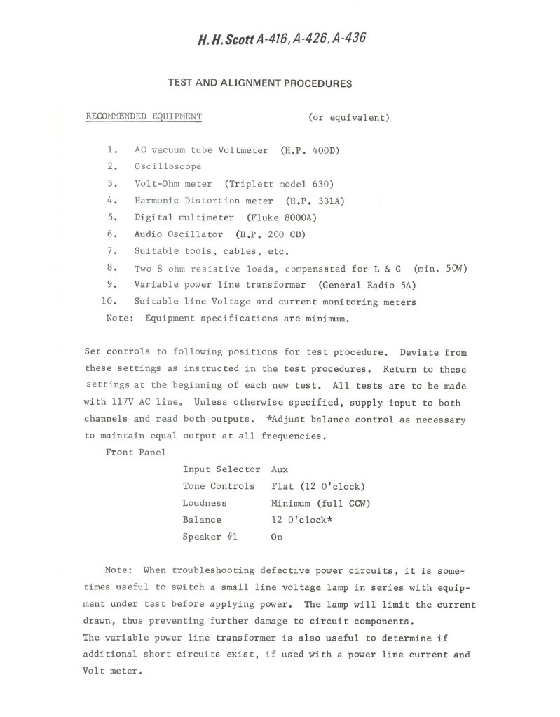
H.H. Scott A-416/A-426/A-436 Test and Alignment Procedures
Test and alignment procedures for H.H. Scott A-416, A-426, and A-436 tube amplifiers. This service manual covers the complete setup and troubleshooting workflow for these classic audio amplifiers, with specifications for essential test equipment, control positioning, and step-by-step audio measurement procedures. Includes detailed measurement tables showing probe placements (positive and negative) at standard reference scales, full circuit diagrams with all component values clearly marked, and separate schematics for the preamp stage, tone control circuits, and power supply sections. An essential workshop resource for anyone servicing or aligning these amplifiers to factory specifications.
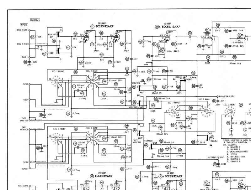
H.H. Scott Model 299B Electronic Schematic Diagram
Complete electronic schematic diagram for the H.H. Scott Model 299B amplifier. This service manual covers the full tube circuit topology, component placement and interconnections, and documented voltage measurements across all amplifier stages. Technicians and vintage audio enthusiasts will find the detailed electrical layout essential for tracking signal flow, identifying component values, and verifying proper operation. The schematic is the authoritative reference for understanding the 299B's dual-channel design and power supply configuration.
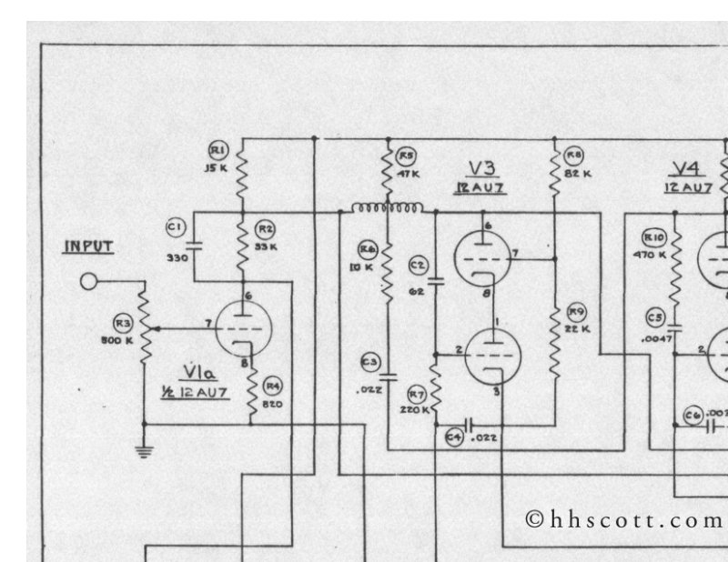
Scott 114-A Dynaural Noise Suppressor Circuit Diagram
Circuit diagram for the Scott 114-A Dynaural Noise Suppressor, a tube-based audio noise reduction unit from the classic hi-fi era. This complete schematic presents the full signal path through two vacuum tube stages employing 12AU7 and 6ALS tubes, along with all associated resistors, capacitors, and output transformers. The diagram includes the power supply topology, range switch configuration for different noise suppression settings, and the dynaural control circuitry that defines this unit's approach to dynamic filtering. Essential reference material for anyone servicing or restoring this vintage audio component, whether for troubleshooting, alignment, or full repair work.
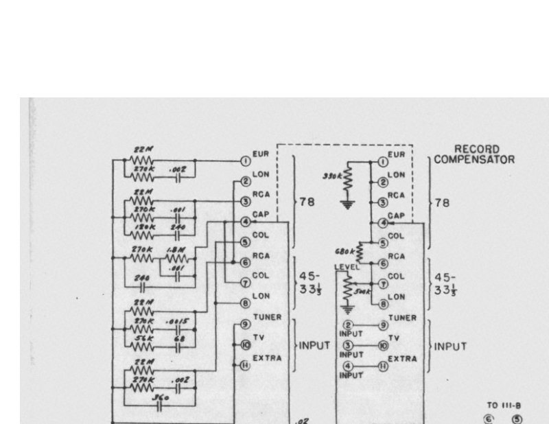
Scott 120-A Equalizer Preamplifier Circuit Diagram
Circuit diagram for the Scott Type 120-A Equalizer Preamplifier, a single-page schematic detailing the complete tube-based audio circuitry. The diagram illustrates the input selector stage, bass and treble tone control circuits, record equalization compensation section, and output amplification stage. Dated January 21, 1953, this service documentation provides the technical reference needed for understanding the signal path, component values, and tube configuration of this classic mid-century preamplifier design. Essential for technicians servicing or restoring vintage Scott audio equipment.
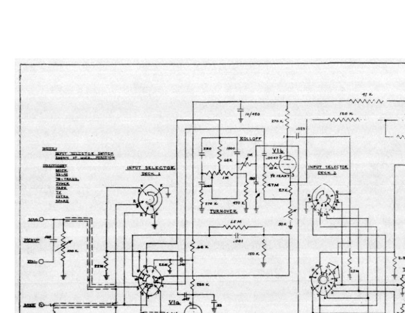
Scott 121A Dynaural Equalizer Preamplifier Circuit Diagram
Complete circuit diagram schematic for the Scott 121A Dynaural Equalizer Preamplifier, a tube-based audio preamplifier designed for high-fidelity playback. The schematic documents the full signal path including input selector switching, tone control circuitry, volume control stages, and output amplification. All component values, resistor and capacitor ratings, tube types, and biasing networks are clearly labeled. An essential reference for understanding the amplifier's signal flow, performing repairs, or restoring this classic Scott audio component to working condition. Ideal for technicians, vintage audio enthusiasts, and anyone servicing or maintaining tube preamplifiers of this era.
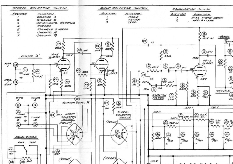
Scott 222A Integrated Amplifier Schematic Diagram
Complete schematic diagram for the Scott 222A integrated amplifier, an essential reference for service technicians and vintage audio enthusiasts working on this classic tube-based amplifier. The detailed drawings illustrate the stereo selector switch, input selector switch, and equalization control circuitry, along with the full tube amplifier topology across both left and right channels. Component values and signal routing are clearly marked throughout, making this schematic indispensable for troubleshooting, repair, maintenance, or restoration work on this sought-after mid-century Scott amplifier.
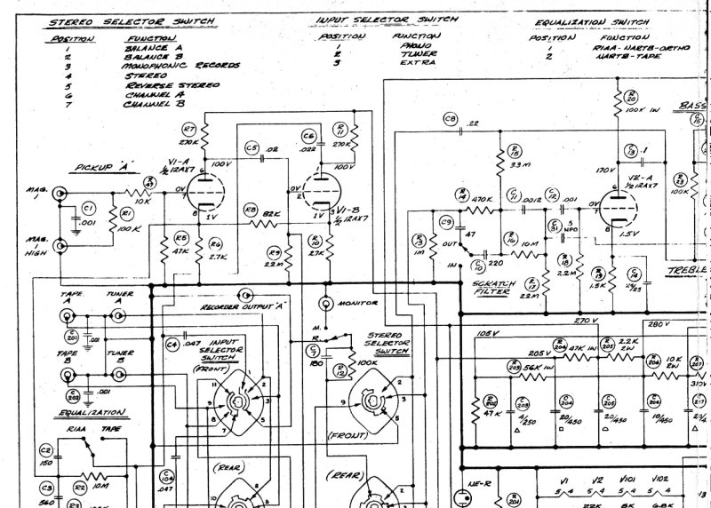
Scott 222B Stereo Amplifier Schematic Diagram
Complete schematic diagram for the Scott 222B stereo amplifier, detailing the full circuit path from input through output stages. Covers the stereo selector switch, input source selector, and equalization network, with all tube positions, resistor and capacitor values clearly marked, along with transformer specifications and wiring routing. Essential reference for service technicians performing circuit analysis, troubleshooting, or restoration work on this classic tube amplifier.
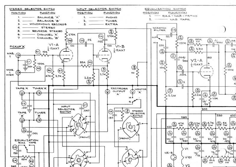
Scott 222C Stereo Amplifier - Electronic Schematic
Complete electronic schematic diagram for the Scott 222C stereo amplifier. This detailed schematic shows both channels (Channel A and Channel B) with all tube-based circuitry including preamp stages, tone controls, power amplifier sections, and output transformers. Includes selector switches for input configuration, equalization circuitry, and recorder output connections. Essential reference for understanding the full signal path, troubleshooting intermittent faults, and performing component-level repairs on this classic mid-century tube amplifier. Ideal for technicians restoring vintage equipment or enthusiasts seeking accurate schematics for reference and maintenance.
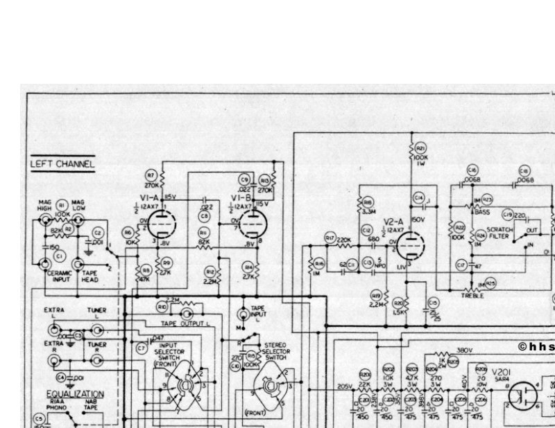
Scott 222D Stereo Amplifier Circuit Diagram
Complete circuit diagram for the Scott 222D stereo amplifier, essential reference for servicing, troubleshooting, and maintenance of this classic tube-based audio component. The schematic maps the left and right channel amplification stages with all vacuum tube positions clearly marked, power supply topology, and speaker output routing. Component values and interconnection details are provided throughout, enabling technicians and enthusiasts to diagnose circuit behavior, trace signal paths, and verify proper operation. Invaluable for understanding the architecture of this mid-century Scott amplifier design.
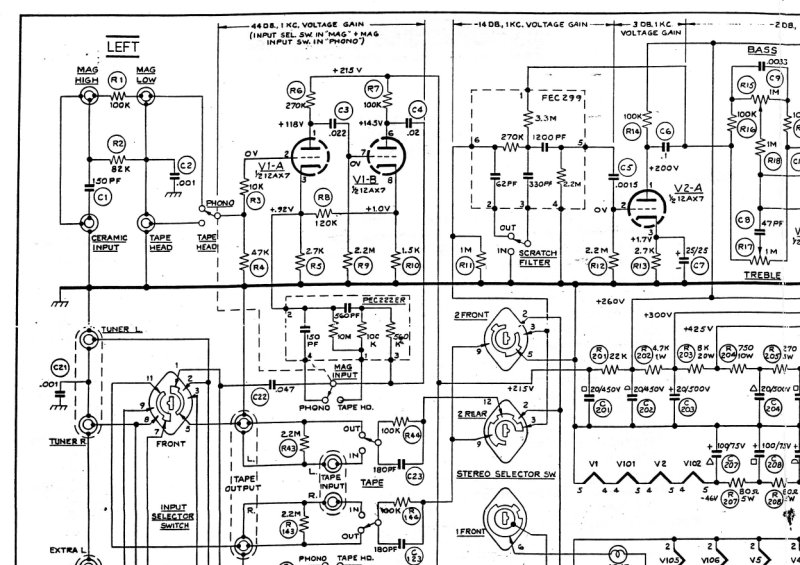
Scott 233 Schematic Diagram
Complete electronic schematic diagram for the Scott 233 tube amplifier. Covers all vacuum tube circuits, voltage gain stages, bass and treble control networks, preamplifier sections, stereo selector switching, output transformers, and speaker connection points with full component values and tube type designations throughout. Essential reference for service work, circuit analysis, restoration projects, or understanding the signal path and biasing of this classic audio amplifier. Includes all resistor and capacitor specifications needed for troubleshooting or component replacement.
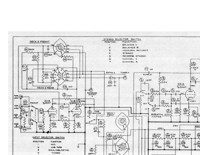
Scott 299C Stereo Amplifier Schematic Diagram
Complete schematic diagram for the Scott 299C stereo amplifier, a tube-based design featuring dual-channel amplification with input and stereo decoder switching. The diagram traces the signal path through bass and treble tone controls, output transformer stages, and tube complement positioning throughout the chassis. Essential for servicing or restoring this classic amplifier, it provides the electrical architecture needed for troubleshooting, component replacement, and design analysis. Includes detailed component placement and tube socket identification for maintenance and repair work.
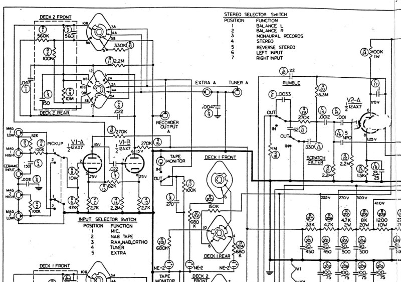
Scott 299D Stereo Amplifier Circuit Diagram
Complete circuit schematic for the Scott 299D stereo amplifier, documenting the full electronic design of this tube-based audio component. The diagram traces the dual-channel signal path for both left and right channels, showing the tube circuits that handle amplification and audio processing. Detailed schematics cover the bass and treble tone control networks, input selector switch configuration, and the power supply sections that distribute voltage throughout the unit. Component values are labeled at every stage, and connection points are clearly marked to support repair work, circuit analysis, or restoration of this classic amplifier. Essential for anyone working on Scott 299D amplifier maintenance or troubleshooting.
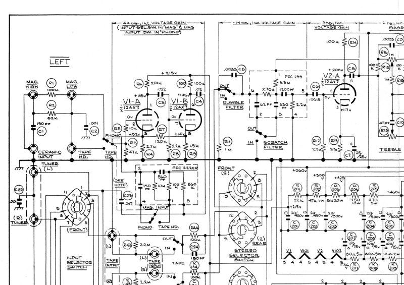
Scott 299D-C1 Amplifier Circuit Diagram
Complete electrical schematic diagram for the Scott 299D-C1 amplifier, showing the full circuit layout with tube stages, voltage gain sections, output transformers, and accessory outlets. The documentation maps the tube complement across both stereo channels, tone control circuits, and balance adjustments—everything you need to trace the signal path and perform maintenance. Essential for technicians repairing, troubleshooting, or restoring this classic Scott audio equipment.
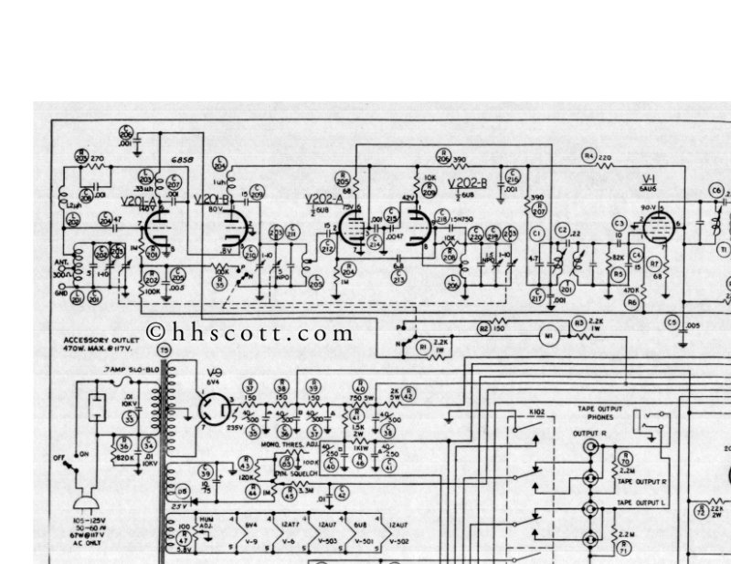
Scott 310E FM Multiplex Stereo Tuner - Schematic Diagram
Complete schematic diagram for the Scott 310E FM multiplex stereo tuner, a tube-based receiver design from the golden age of hi-fi audio. This workshop reference document maps the entire signal path from RF input through intermediate frequency amplification, multiplex stereo decoding, and output stages. Detailed component layouts and interconnections throughout the chassis make this schematic essential for troubleshooting, restoration work, and understanding the classic vacuum tube architecture that defined this tuner.
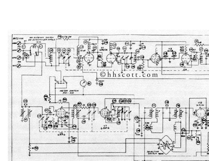
Scott 330 Amplifier Schematic Diagram
Complete schematic diagram for the Scott 330 tube amplifier, detailing the full electronic circuit topology from input through output stages. Includes precise component layout, connection diagrams, and all part values needed for troubleshooting, repair, and circuit analysis across both signal path and power supply sections. Essential reference for technicians servicing or restoring this classic amplifier, as well as for anyone performing maintenance or modifications.
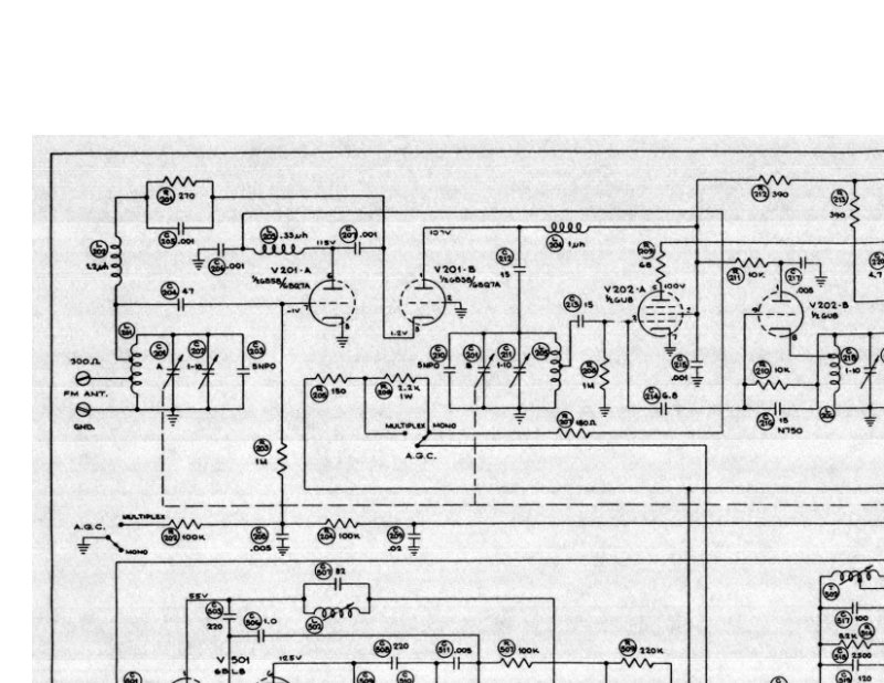
Scott 333A AM/FM Tuner Schematic Diagram
Complete schematic diagram for the Scott 333A AM/FM tuner, spanning 2 pages of detailed electronic circuit layouts. This repair manual includes full tube component schematics, resistor and capacitor networks, transformer specifications, and all associated wiring paths. The diagram set covers front and rear deck layouts, function switch configurations, and antenna connection details—essential reference material for service technicians working on this classic mid-century tuner.
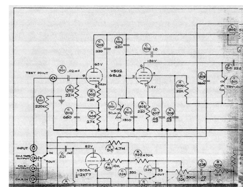
Scott 335 Circuit Diagram Schematic
Complete circuit diagram schematic for the Scott 335 audio amplifier, a single-page technical drawing dated May 25, 1961. This schematic documents the full electronic architecture, including all tube circuits, resistor and capacitor networks, power supply section, dual stereo input channels, and input selector switch. Component reference designations and voltage measurements are clearly marked throughout, making this an essential service reference for understanding the signal path, bias networks, and operating parameters of this classic tube amplifier. Ideal for technicians performing repair, maintenance, or restoration work on the Scott 335.
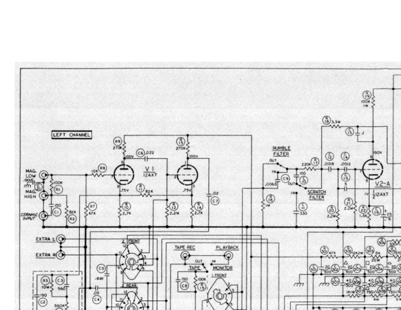
Scott 340B Circuit Diagram - Sheet 1 & 2
Complete two-page circuit schematic for the Scott 340B stereo audio amplifier. This service documentation provides detailed electrical diagrams showing tube positions, component layouts, and signal routing between left and right channels. Essential reference material for technicians performing maintenance, troubleshooting, or restoration work on this classic H.H. Scott amplifier. The circuit diagrams illustrate the tube complement, resistor networks, capacitor placements, and all interconnection paths needed to understand the amplifier's architecture. Manufactured by H.H. Scott, Inc.
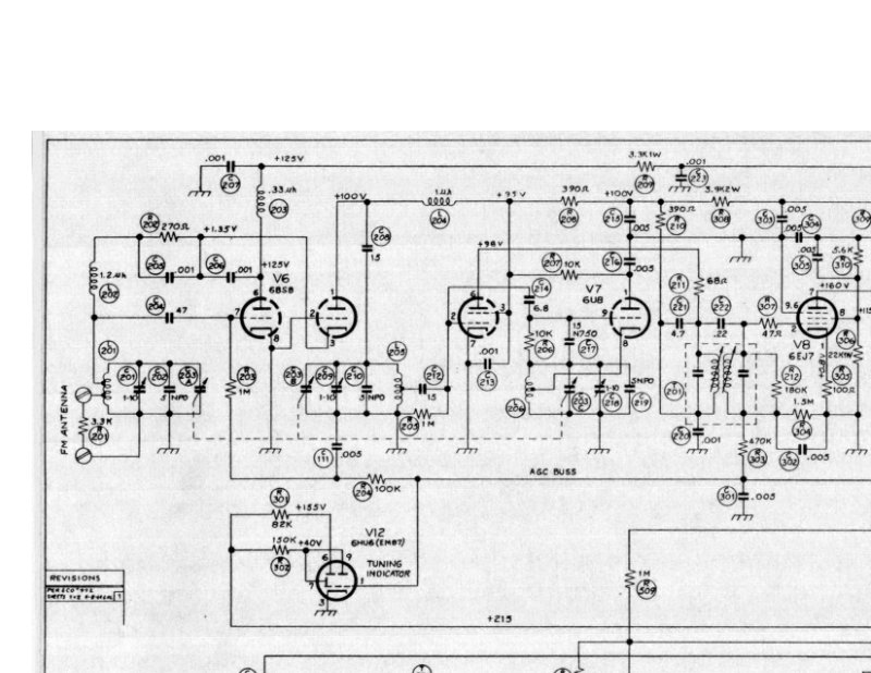
Scott 345 Circuit Diagram - Schematic
Complete circuit diagram and schematic for the Scott 345 tube amplifier. This three-sheet service document provides detailed tube-based audio circuitry with all component connections, tube socket positions, and signal flow paths clearly mapped across left and right channels. Covers the power supply section and selector switch circuits essential for troubleshooting, repair, and maintenance of this classic amplifier. Ideal for technicians restoring or servicing the Scott 345.
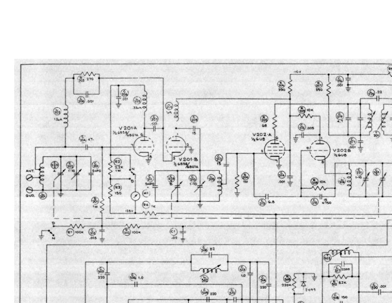
Scott 350B Circuit Schematic Diagram
Complete circuit schematic diagram for the Scott 350B tube amplifier. This single-page schematic details the full electronic architecture, including the power supply, preamp stage, and output stage circuitry. Essential reference material for anyone servicing, troubleshooting, or studying the design of this classic Scott amplifier.
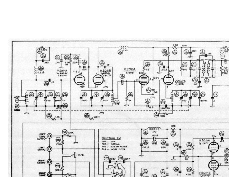
Scott 350D Circuit Diagram Schematic
Complete electronic circuit diagram and schematic for the Scott 350D amplifier—an essential technical reference for service and troubleshooting. Covers the full tube complement, power and output transformers, resistors, capacitors, and associated circuitry. Includes a voltage measurement reference table critical for fault diagnosis and component verification. Ideal for technicians performing repairs, alignment work, or restoring vintage audio equipment.
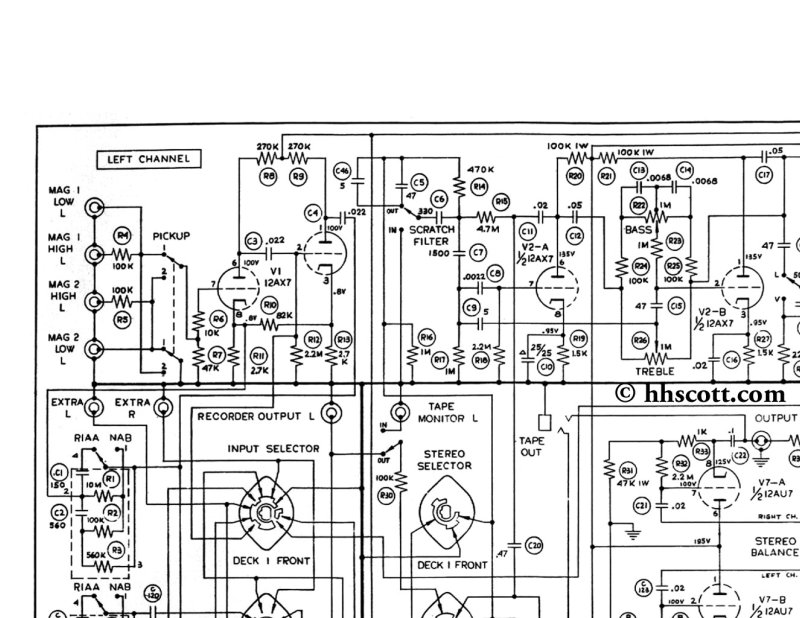
Scott 355 AM-FM Multiplex Stereo Control Center Schematic
Complete electronic schematic for the Scott 355 AM-FM multiplex stereo control center, a vintage tube-based audio control unit. This two-page technical diagram details the full signal path across left and right channels, input selector switching, tape output routing, loudness compensation controls, and the tuner section with separate AM and FM circuit configurations. Includes power supply connections and component-level tube circuitry throughout. Essential reference for service and repair of this classic mid-century stereo preamplifier and tuner control module.
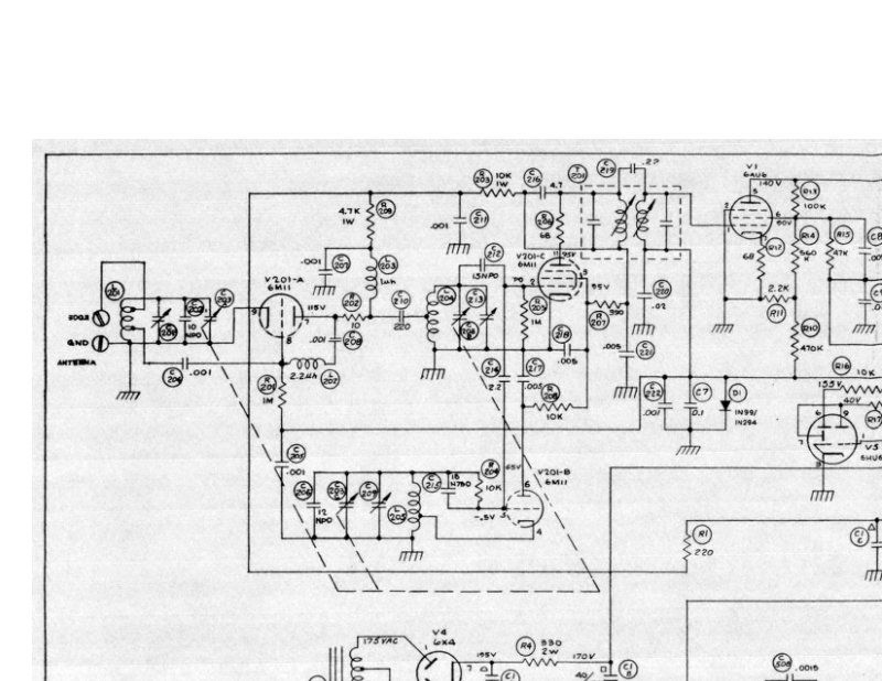
Scott 370 A and B Schematic Diagram
Complete schematic diagram for Scott 370 A and B tube amplifiers, detailing the full vacuum tube circuitry with all component connections and voltage reference points. This service document provides the precise circuit layout and transformer secondary output specifications needed for troubleshooting, repair, and maintenance of these classic tube-based audio amplifiers. Essential reference for technicians restoring Scott vintage amplifiers.
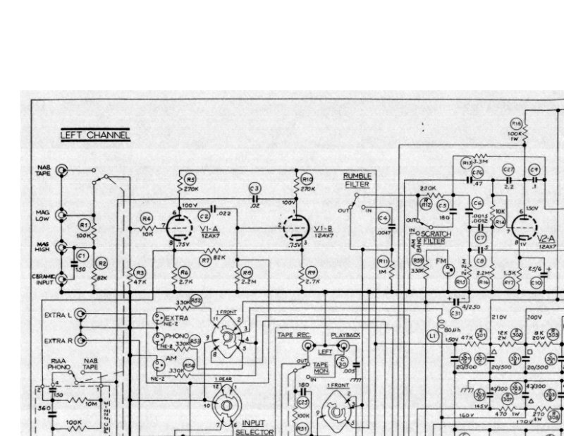
Scott 380 Receiver - Complete Circuit Diagram
Complete 2-page circuit diagram for the Scott 380 tube receiver. Documents the left and right channel signal paths, input selector switching, tone control circuitry, push-pull power amplifier stages, and output transformers with all component values and interconnections clearly marked. Essential reference for servicing, troubleshooting, or restoring this classic vintage audio receiver. Schematic shows the full tube-based topology typical of Scott's mid-century design approach.

Scott 420A Integrated Stereo Amplifier Service Manual
Service manual for the Scott 420A integrated stereo amplifier, providing technicians and enthusiasts with comprehensive repair and maintenance guidance. The document includes detailed schematic diagrams, component layouts, tube configurations, and complete electronic circuit schematics necessary for troubleshooting, service, and restoration work. Essential reference for anyone performing amplifier repair, restoration, or maintenance on this vintage Scott model.

Scott 665DM Stereo Cassette Deck Service Manual
Service manual for the Scott 665DM stereo cassette deck. This workshop repair guide contains the complete schematic diagram for the European model, detailing transistor and integrated circuit configurations including IC301, IC302, and IC601. The manual features a comprehensive component reference list with semiconductor specifications and a voltage reference table essential for troubleshooting and alignment procedures. An invaluable resource for technicians servicing this classic tape deck platform.
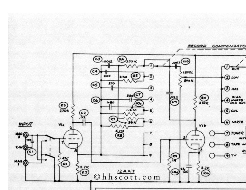
Scott 99B Amplifier Schematic Diagram
Complete electronic schematic diagram for the Scott 99B audio amplifier, detailing the record compensator circuit, input stage, output stage with tubes, power supply topology, and all associated component networks. This service manual schematic provides the technical reference needed for amplifier repair, maintenance, and troubleshooting of this classic tube amplifier design.
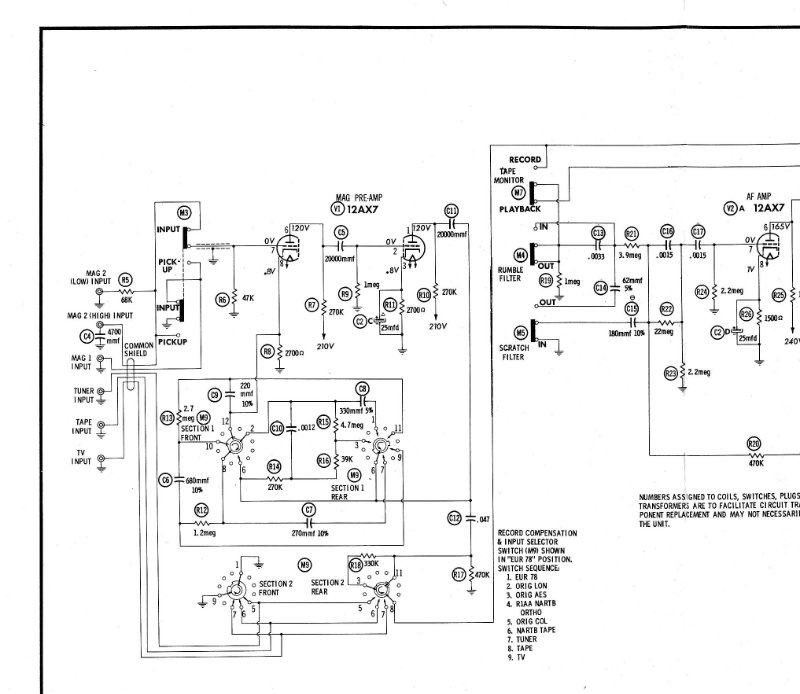
Scott 99D Electronic Schematic Diagram
Complete electronic schematic diagram for the Scott 99D integrated amplifier. Shows detailed circuit layouts with tube positions, component values, and wiring connections throughout all amplifier sections. An essential reference for service technicians performing maintenance, troubleshooting, and component-level repairs on this classic tube amplifier.
Scott CD-67/67R Stereo Cassette Deck Operating Manual
Operating manual for the Scott CD-67 and CD-67R stereo cassette decks. Covers installation, operation, maintenance, and technical specifications with connection diagrams. Includes detailed front and rear panel layouts with numbered control references, Dolby noise reduction system, tape type selectors for standard and chrome/CrO2 formulations, and independent left/right channel volume controls. Also provides troubleshooting guidance for common performance issues.
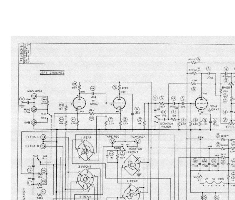
Scott D-340-CI Tuner Amplifier Schematic Diagram
Complete schematic diagram for the Scott D-340-CI FM multiplex stereo tuner amplifier. This two-page technical schematic provides the full circuit design across tube-based amplification stages, input selector switching, stereo detector circuits, and output amplifier sections. Includes detailed accessory connector pinouts and power supply circuit topology. Essential reference for service work, troubleshooting, or restoration of this classic mid-century integrated amplifier.
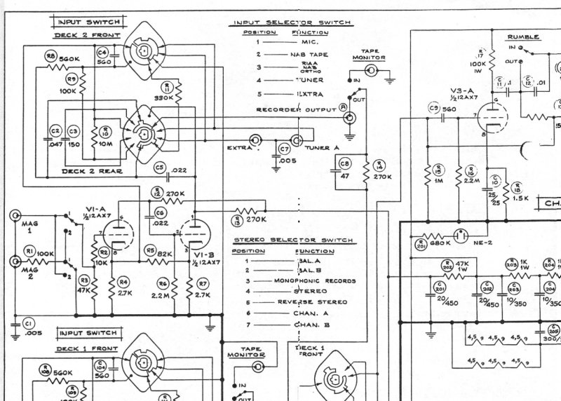
Scott LC-21 Stereo Control Center Kit Schematic
Complete electrical schematic diagram for the Scott LC-21 Stereo Control Center Kit, an essential service reference for technicians and hobbyists maintaining or repairing this classic tube-based audio control unit. The diagram details dual deck configurations with separate front and rear connections for Deck 1 and Deck 2, stereo selector circuitry, and comprehensive input selection routing that accommodates microphone, phono, tape monitor, and auxiliary signal paths. Includes the full tube-based audio amplification circuit topology with volume control, loudness compensation, and independent treble and bass tone shaping for both stereo channels A and B. Power supply schematic and all accessory connection points are clearly mapped, making this workshop manual excerpt invaluable for troubleshooting, component-level repair, and understanding the signal chain of this mid-century control center design.
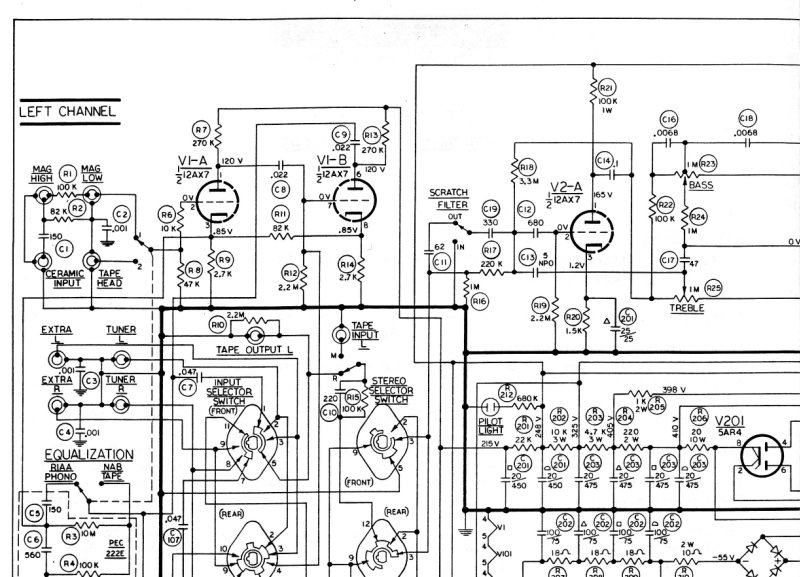
Scott LK48B Stereo Amplifier Circuit Diagram
Complete circuit diagram for the Scott LK48B stereo amplifier, providing a comprehensive schematic of both left and right channel signal paths. The diagram maps out the vacuum tube stages from V1-A through V5-B, tracing signal flow through the input selector, equalization network, and stereo selector before reaching the power supply section. This service manual schematic includes component layout and tube identification essential for troubleshooting, repair, and maintenance of vintage tube amplifiers. Ideal for technicians restoring or servicing this classic mid-century Scott audio electronics design.
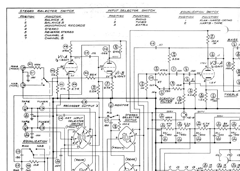
Scott LK72A Stereo Amplifier - Electronic Schematic
Complete electronic schematic for the Scott LK72A stereo amplifier kit, detailing the dual-channel amplifier circuit architecture with tube stages throughout the signal path. Covers input selector switching logic, equalization circuit design, tone control networks, and output transformers. Schematic includes all component values and tube socket positions—essential reference material for troubleshooting, repair work, and understanding the amp's original configuration. Ideal for technicians rebuilding or servicing vintage tube amplifiers, or enthusiasts restoring this classic Scott kit to working condition.
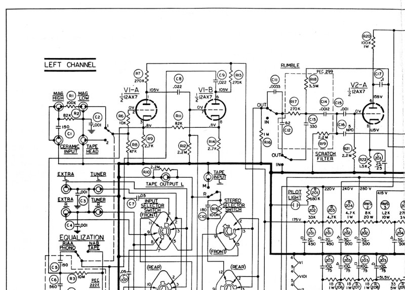
Scott LK72B Stereo Receiver Circuit Diagram
Complete circuit diagram for the Scott LK72B stereo receiver, a detailed technical schematic essential for repair, maintenance, and troubleshooting. Documents the full signal path across both left and right channels, including tube amplifier stages, input selector network, stereo mode switching, equalization circuitry, loudness compensation, and power control sections. Covers output stage topology, speaker terminal connections, and accessory outlet wiring. This service documentation provides technicians and experienced enthusiasts with the complete electrical blueprint needed for circuit analysis, component tracing, and restoration of this classic mid-century stereo receiver.
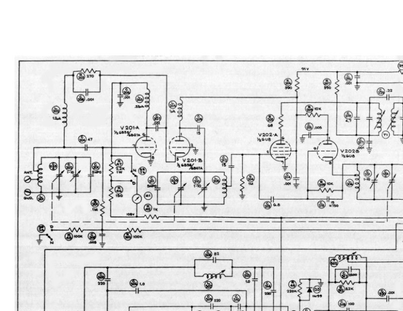
Scott LT110 Schematic Diagram
Complete electronic schematic diagram for the Scott LT110 model. This single-page service reference provides detailed circuit layout showing tube positions, component values, and all interconnections — essential reference material for troubleshooting, repair work, or restoration of this classic Scott amplifier. The diagram clearly identifies each component and its placement within the circuit, making it invaluable for technicians performing maintenance or diagnostics on tube-based audio equipment from this era.
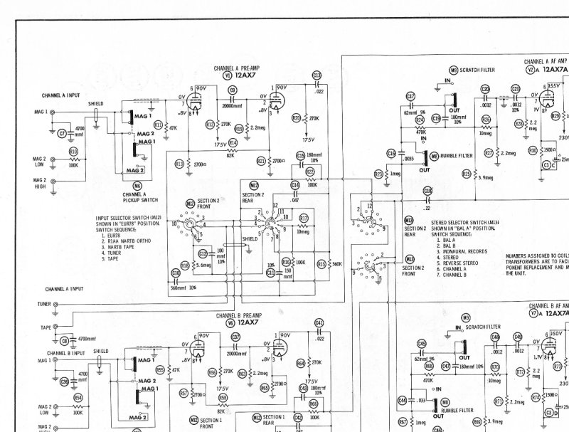
Scott Model 299 Schematic Diagram
Schematic diagram for the Scott Model 299 tube audio amplifier. This detailed technical drawing maps out the complete electronic circuit architecture, including input channel configuration, preamp gain stages, output driver and power amp sections, and the full power supply topology. Includes reference tables listing all resistor and capacitor values throughout the circuit. Essential for troubleshooting, repair, alignment, and understanding the amplifier's signal path and biasing arrangements.
Scott R326L Stereo Amplifier Tuner FM-PO/GO User Manual
User manual for the Scott R326L stereo amplifier-tuner, a comprehensive owner's guide covering setup, operation, and connections for this FM-PO/GO integrated receiver. Includes specifications, step-by-step installation instructions, and detailed connection diagrams for all audio inputs and outputs. Covers operation of the FM and AM tuner sections, tape deck recording and playback integration, microphone input setup, speaker connection and impedance matching, tone and filter control adjustment, and auxiliary AC power connections. Features front panel control identification and full operating procedures for daily use. This workshop manual and parts reference serves both novice users setting up the system and experienced technicians performing maintenance or troubleshooting on vintage Scott audio equipment.
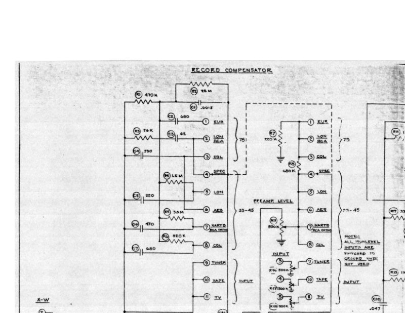
Scott Type 120-CP Equalizer Preamplifier Circuit Diagram
Complete circuit diagram and technical schematic for the Scott Type 120-CP Equalizer Preamplifier, a classic vacuum-tube audio component. This service documentation details the record compensator network, loudness contour control, regulated power supply section, and output driver stage. Essential reference for understanding tube-based preamp circuitry, troubleshooting audio performance issues, and locating component values and tube specifications. Includes all signal paths and component interconnections needed for maintenance and repair work on this vintage audio equipment.
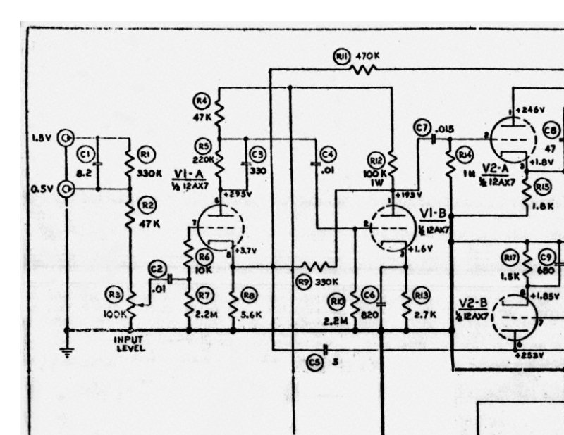
Scott Type 250 Laboratory Power Amplifier Schematic
Complete electrical schematic diagram for the Scott Type 250 Laboratory Power Amplifier. This single-page service document presents the tube-based amplifier circuit with all voltage points and component designations clearly marked. The schematic covers the power transformer section, output connections, and identifies all tube positions throughout the circuit. Essential reference for technicians performing maintenance, troubleshooting, or restoration work on this vintage tube amplifier, and invaluable for understanding signal flow and component layout during repair or modification.
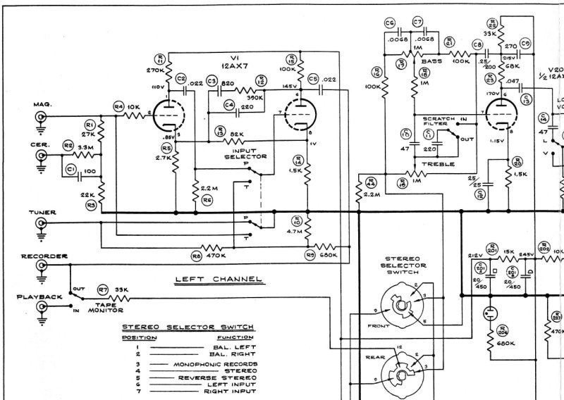
Scott Type LC-30/200 Dual Channel Laboratory Amplifiers
Complete electronic schematic diagram for the Scott Type LC-30/200 dual channel laboratory amplifiers. This service manual schematic details the left and right channel circuits, showing tubes, resistors, capacitors, transformers, and speaker connections. The diagram covers the stereo selector switch, input selector, volume and loudness controls, bass and treble tone adjustments, tape monitor circuits, and power supply sections across a single page with clear component identification and signal path routing. An essential reference for understanding amplifier circuit topology and troubleshooting component-level issues.