TANDBERG - Service Manuals
2 manuals available for download
TANDBERG has established itself as a trusted manufacturer in professional audio and HiFi equipment, with a legacy spanning decades of high-quality engineering and design. Our collection of TANDBERG service manuals and technical documentation provides technicians, enthusiasts, and repair professionals with the comprehensive resources needed for maintenance, troubleshooting, and component-level repairs. Whether you're seeking a detailed service manual, workshop guide, or parts list for your equipment, our PDF downloads offer authentic manufacturer documentation that covers schematics, repair procedures, and maintenance protocols to keep your TANDBERG audio systems performing at their best.
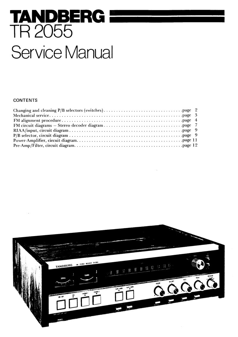
Tandberg TR2055 Service Manual
Service manual for the Tandberg TR2055 FM stereo receiver, providing technicians and experienced enthusiasts with comprehensive repair and maintenance guidance. Covers procedures for servicing push button switches—including cleaning, lubrication, and P/B alignment—along with detailed mechanical maintenance throughout the unit. Features complete circuit diagrams for the FM stereo decoder section, RIAA/input stage, push button selector circuit, power amplifier, and pre-amp/filter network. Includes step-by-step dismantling instructions for contact cases, plungers, cabinet assembly, RIAA input board, scale cover and housing components, meter lamps, output transistors, FM stereo indicator lamp, and scale drive cord mechanism. Dedicated section on FM stereo decoder alignment procedures with full equipment specifications and systematic alignment steps to restore optimal tuning performance. Essential reference for bench service and restoration of this classic receiver.
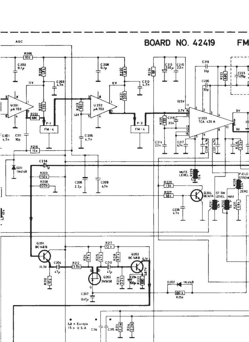
Tandberg TR2075 FM-IF Decoder Schematic
Electronic schematic diagram for the FM-IF decoder section of the Tandberg TR2075 radio receiver. This service manual covers Board No. 42419 in detail, showing the tube-based circuitry, component layout, and all interconnections needed for maintenance and troubleshooting. The schematic includes the complementary FM-tuner board (Board No. 41009) and provides a printed circuit board view from the solder side for reference during repair work. Applies to serial number 1453001 and later. Essential technical documentation for servicing this classic receiver.