MINOLTA - Minolta Dynax7 Repair
 by MINOLTA
Comprehensive repair guide for the Minolta Dynax 7 SLR camera. This technical manual provides detailed disassembly and adjustment procedures essential for servicing and repairing this professional photographic instrument. The guide systematically covers the disassembly of all external assemblies, including back cover, front cover, top cover, and internal components such as mirror box assembly, battery holder, image board, and main board assemblies. Precise instructions are provided for shutter assembly replacement and critical post-repair adjustments. The document emphasizes safety procedures including main capacitor discharge before disassembly, electrostatic discharge protection for MOS integrated circuits, and proper handling guidelines for plastic parts and volatile chemicals. A substantial section addresses adjustments using the HIT system, encompassing CCD position adjustment, image stabilization compensation, white balance calibration, sensitivity testing, defective pixel detection, and various AF and exposure function calibrations. The manual also includes information on required measuring instruments and subsidiary materials necessary for conducting all interventions. Wire arrangement diagrams and detailed part identification are provided throughout to facilitate accurate repair work.
Table of Contents:
- Repair guide
- Repair guide
- This repair guide section contains the disassembly and adjustment procedures.
- For the assembly procedure, follow the reverse procedure.
- Symbols
- ■:Cautions and keypoints
- : Grease
- : Adhesive
- : Tool
- ■Precautions --------------------------------------------- 2
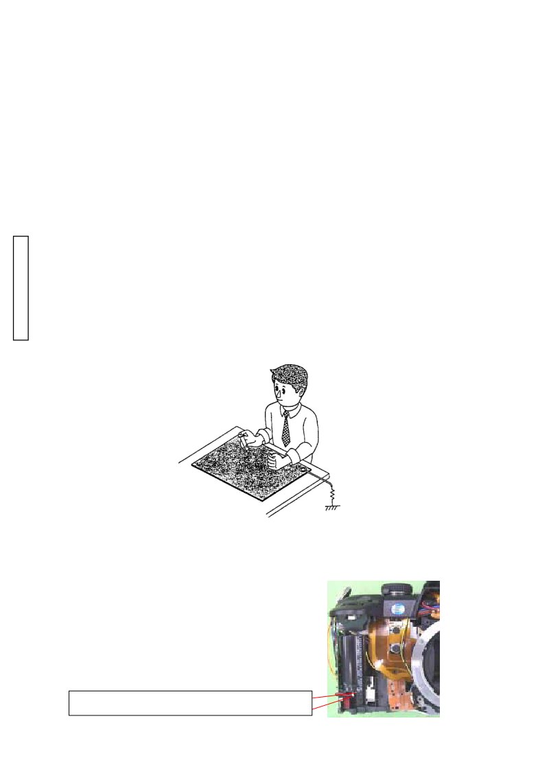
- ■Discharge ------------------------------------------------ 2
- ■To inhibit flash charge ------------------------------- 3
- ■To activate without exterior parts ----------------- 3
- 1. Disassembly of the exterior parts ------------------ 4
- ■ Wires arrangement ----------------------------------- 5
- 2. Disassembly of the TEBURE ASSY,
- Shutter assy----------------------------------- 7
- 3. Disassembly of the MIRROR BOX ASSY,
- Battery holder ----------------------------- 10
- 4. Disassembly of the IMAGE BOARD ASSY,
- Main board assy ----------------------------- 11
- 5. Disassembly-1 of the MIRROR BOX ASSY ----- 13
- 6. Disassembly-2 of the MIRROR BOX ASSY ----- 15
- 7. Disassembly-3 of the MIRROR BOX ASSY ----- 17
- 8. Disassembly of the TOP COVER ASSY --------- 20
- 9. Disassembly of the BACK COVER ASSY ------- 24
- 10. Disassembly of the CCD ASSY,
- Dc jack holder ------------------------------ 26
- 11. Disassembly of the CARD COVER HOLDER,
- Side cover, front cover assy ------- 27
- ■How to replace "SHUTTER ASSY"--------------- 28
- ■Required adjustment, setting and confirmation
- items after repairing (exchanging parts) -------- 30
- ■Related adjustment and
- required setting items ---------------------------- 32
- ■Using HIT System ----------------------------------- 33
- ■Adjustment/Check items available
- with 2181 ROM Pack ---------------------------- 34
- ■Viewfinder Back Adjustment ---------------------- 35
- ■Manual Set SS & X-Sync. Time-lag Check ----- 36
- ■Manual Set SS Adjustment ------------------------ 37
- ■SPC Position Adjustment --------------------------- 38
- ■Aperture Preset Check/Adjustment -------------- 39
- ■PI-PR Adjustment ------------------------------------ 40
- ■Preparation before AF adjustment --------------- 42
- ①AF Area Adjustment --------------------------------- 43
- ② Pitch Yaw Adjustment ------------------------------ 44
- ③ EZ Check ----------------------------------------------- 45
- ④EZ Adjustment ---------------------------------------- 46
- ■Assist MODE ------------------------------------------ 47
- ■LCD Displays Check--------------------------------- 47
- ■Preparing the 2181 adjustment program ------- 48
- ■Starting up the 2181 adjustment program
- (in the adjustment mode). ----------------------- 49
- ■Back up Flash ROM data of Master Body ------ 50
- ■Adjustment of CCD Vsub voltage ----------------- 51
- ■Setting of Master body and chart for the
- adjustment of CCD position --------------------- 52
- ■Adjustment of CCD position and perspective --- 53
- ■Adjustment of the frequency for
- camera shaking (ACT DRV FREQ) ----------- 55
- ■Adjustment of the servo for
- camera shaking (SERVO) ----------------------- 55
- ■Adjustment of the gyro for
- camera shaking (GYRO) ------------------------- 55
- ■Adjustment of the AE (AE) ------------------------- 56
- ■Sensitivity adjustment (GAIN) -------------------- 57
- ■Adjustment of the defective pixel
- (defect pixel) --------------------------------- 58
- ■Adjustment of white balance (WB) --------------- 59
- ■Adjustment of the camera shaking
- compensation (SHAKE GAIN) ----------------- 60
- ■Distination Seting(DISTINATION) -------------- 61
- ■Light Source-A Maintenance ----------------------- 62
- ■Error code on adjustment program--------------- 63
- ■Measuring instrument ------------------------------ 65
- ■Subsidiary Materials--------------------------------- 66
Documentation must be downloaded on a computer (PC, Mac, or Linux).
Do not use a smartphone or tablet to download documentation; they generally lack sufficient memory capacity to handle large files, and few users know how to locate the download folder on these devices.
Once downloaded, you can use it right away and even print the pages you need, or use your smartphone in photo mode to translate into the language of your choice: Google Translate
Document Details
- Format
- Pages
- 66
- Size
- 2.3 MB
- Category
- Photography