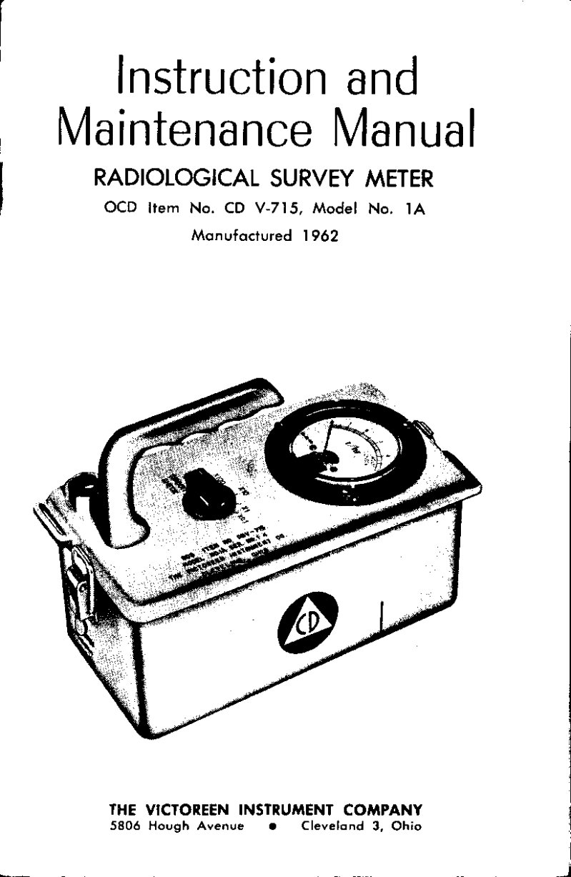
CD V-715 Model 1A Radiological Survey Meter Manual
Instruction and maintenance manual for the CD V-715 Model 1A radiological survey meter, manufactured by Victoreen Instrument Company in 1962. This comprehensive service manual covers essential precautions for working with high-impedance circuits and semiconductor components, foundational descriptions of sensing elements and electronic circuitry design, and detailed theory of operation explaining ionization chamber and measuring circuit behavior. Installation procedures walk through proper setup, while operational adjustments address zero calibration and circuit verification. Battery replacement, cleaning protocols, and systematic troubleshooting guidance enable field technicians to maintain reliable detector performance. Complete with schematic circuit diagram, circuit board assembly illustrations, and detailed parts lists for both electrical and mechanical components, this workshop manual serves as the authoritative reference for repair, calibration, and preventive maintenance of this classic radiation detection instrument. Table of Contents: - Section 1. Precautions .... page 3 - 1.1 High Impedance Circuitry .... page 3 - 1.2 Semi-Conductor Components .... page 3 - 1.3 Electrometer Tube .... page 3 - Section 2. General Description .... page 3 - 2.1 Introduction .... page 3 - 2.2 Sensing Element .... page 3 - 2.3 Electronic Circuitry .... page 4 - 2.4 Battery .... page 4 - 2.5 Meter and Controls .... page 4 - 2.6 Physical Features .... page 4 - Section 3. Theory of Operation .... page 4 - 3.1 Ionization Chamber .... page 4 - 3.2 Input Circuit .... page 5 - 3.3 Measuring Circuit .... page 5 - 3.4 Power Supply Circuit .... page 5 - Section 4. Installation .... page 7 - 4.1 Inspection .... page 7 - 4.2 Battery Installation .... page 7 - 4.3 Shoulder Strap Installation .... page 7 - Section 5. Operation .... page 7 - 5.1 Adjustments and Readings .... page 7 - Step 1. Zero Adjust .... page 7 - Step 2. Circuit Check .... page 8 - Step 3. Range Selection and Reading .... page 8 - Section 6. Operator's Maintenance .... page 8 - 6.1 Battery Replacement .... page 8 - 6.2 Cleaning .... page 9 - Section 7. Preventive Maintenance .... page 9 - 7.1 Preventive Maintenance .... page 9 - Section 8. Corrective Maintenance .... page 9 - 8.1 Calibration .... page 9 - 8.2 Disassembly for Corrective Maintenance .... page 10 - 8.3 Trouble Shooting .... page 10 - Section 9. Replaceable Parts Lists .... page 14 - 9.1 Electrical Components .... page 14 - 9.2 Mechanical Components .... page 15 - 9.3 List of Manufacturers .... page 16 - Figure 1. View of CD V-715, Showing Operating Controls .... page 2 - Figure 2. View of CD V-715, Showing Major Components .... page 2 - Figure 3. Simplified Schematic Circuit Diagram .... page 6 - Figure 4. Method of Attaching Shoulder Straps .... page 7 - Figure 5. Circuit Board Assembly .... page 12 - Figure 6. Schematic Circuit Diagram .... page 13