BRIDGEPORT - Service Manuals
49 manuals available for download
Bridgeport is a trusted name in precision machine tools, recognized worldwide for manufacturing robust milling machines and industrial equipment built to last. Whether you need a comprehensive service manual, detailed repair manual, or complete owner's manual for maintenance and troubleshooting, our collection of Bridgeport technical documentation provides the essential guidance required for proper operation and upkeep. Access PDF downloads of workshop manuals, parts lists, and maintenance guides that help technicians and operators keep their equipment running at peak performance.
360 & 360/3D Tracer Valves Service Manual
Service manual for Bridgeport True-Trace 360 and 360/3D tracer valves, covering Series C-360, D-360 (High-Flow), C-360/3D, and D-360/3D (High-Flow) models. This workshop manual includes tracer valve identification and installation guidance, lubrication and startup procedures, control system descriptions, valve adjustment specifications, 360 tracer nose calibration, parts list cross-reference, hydraulic system air removal procedures, plumbing schematics, and the M-302A troubleshooting guide along with field service bulletins. A key insight throughout the manual: approximately 90 percent of reported service issues originate from machine tool configuration rather than tracer valve failure, and most can be resolved through straightforward adjustment and maintenance steps rather than component replacement.
612 & 618W Autostep III Surface Grinder Manual
Instruction manual for the Bridgeport/Harig 612 and 618W Autostep III surface grinder. This workshop manual covers installation and setup procedures, operational fundamentals including essential safety precautions, component nomenclature, spindle motor startup, oil pump operation, longitudinal and crossfeed mechanisms, elevating adjustments, autostep downfeed control, and magnetic chuck mounting for grinding wheels. Maintenance sections address cleaning protocols, lubrication schedules, and hydraulic system upkeep to keep the machine running reliably. Comprehensive troubleshooting and adjustment procedures tackle common operational issues: chatter and vibration marks, longitudinal scratching, surface finish irregularities, grinding accuracy problems, motor malfunctions, oil leakage, uneven autostep response, longitudinal feed issues, and crossfeed problems. The manual includes technical drawings and complete part numbers for ordering replacement components, making it essential for operators and maintenance technicians managing this precision grinding equipment.
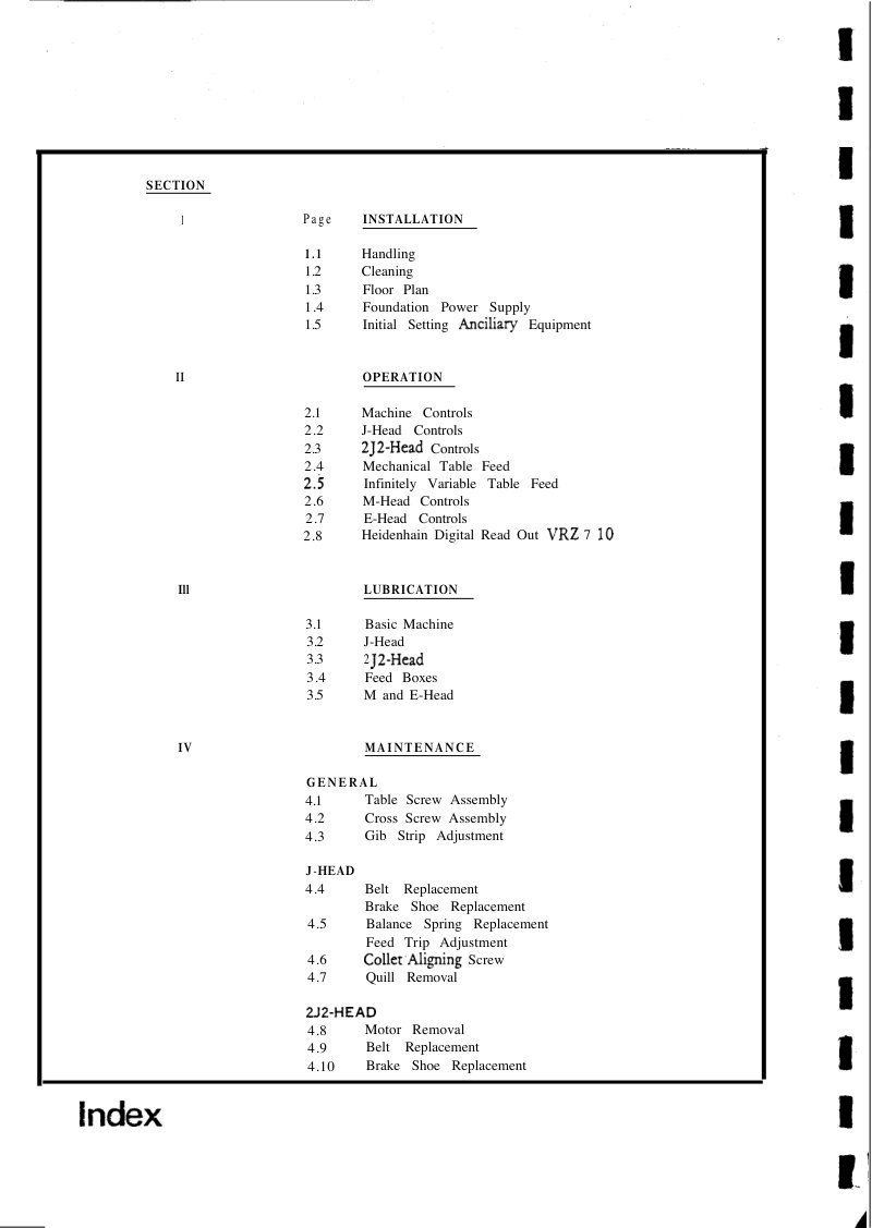
Bridgeport BRJ/BR2J2 Operation & Maintenance
Operation and maintenance manual for Bridgeport Series 1 vertical milling machines, covering models BRJ and BR2J2. This workshop manual provides detailed guidance on machine installation, setup, and configuration of all available head assemblies (J-Head, 2J2-Head, M-Head, and E-Head options). Includes comprehensive coverage of mechanical and variable table feed systems, the Heidenhain Digital Read Out VRZ 7 10 interface, and systematic lubrication schedules for both the base machine and head components. Maintenance procedures address screw assemblies, gib strip adjustment, belt tensioning and replacement, brake shoe replacement, balance spring service, and quill extraction techniques. A thorough troubleshooting and repair resource for operators and technicians responsible for keeping these machines in reliable working order. Table of Contents: - INSTALLATION - Handling - Cleaning - Floor Plan - Foundation Power Supply - Initial Setting Ancillary Equipment - OPERATION - Machine Controls - J-Head Controls - 2J2-Head Controls - Mechanical Table Feed - Infinitely Variable Table Feed - M-Head Controls - E-Head Controls - Heidenhain Digital Read Out VRZ 7 10 - LUBRICATION - Basic Machine - J-Head - 2J2-Head - Feed Boxes - M and E-Head - MAINTENANCE - GENERAL - Table Screw Assembly - Cross Screw Assembly - Gib Strip Adjustment - J-HEAD - Belt Replacement - Brake Shoe Replacement - Balance Spring Replacement - Feed Trip Adjustment - Collet Aligning Screw - Quill Removal - 2J2-HEAD - Motor Removal - Belt Replacement - Brake Shoe Replacement
Bridgeport Digital Readout System Manual
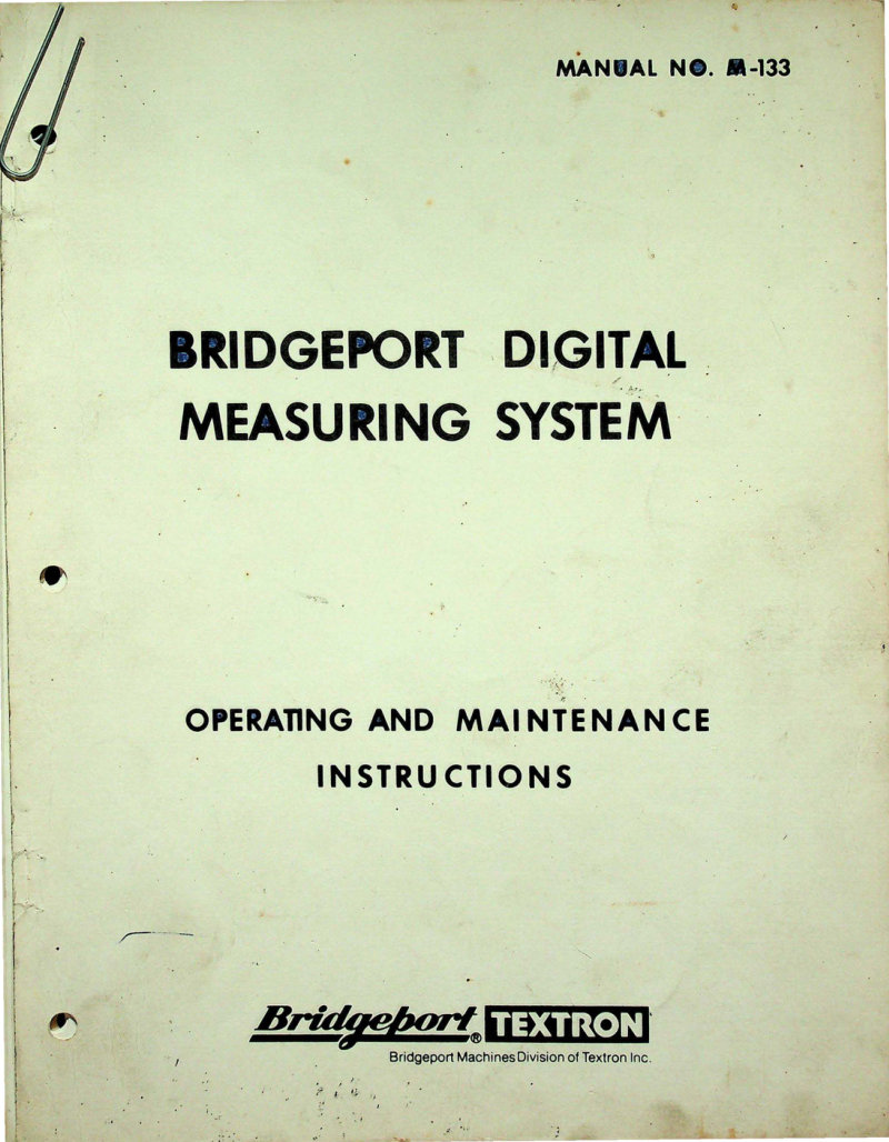
Complete operating and maintenance manual for the Bridgeport Digital Readout System model M-133, published September 1981 by Bridgeport Machines Division of Textron Inc. This workshop manual covers setup, calibration, and troubleshooting of the M-133 digital readout unit, including display functionality, sensor interface, electrical connections, and routine maintenance protocols. An essential reference for machine operators and technicians responsible for Bridgeport digital positioning equipment on CNC or manual milling machines. Table of Contents: - INTRODUCTION - OPERATION - SYSTEM DESCRIPTION - General - Readout Unit - Transducers - DEFINITIONS OF TERMS AND READOUT FUNCTIONS - Definitions of Terms - Numerical Displays - Indicator Lamps - Axis and Mode Select Keys - Numerical Input Keys - Auxiliary Function Keys - Switches - OPERATING EXAMPLES - Operating Notes - Example 1: Establishing Absolute Zero Position - Example 2: Incremental Moves - Example 3: Absolute Coordinate Translated to an Incremental Move - Example 4: The Recall Feature - Example 5: The Calculator Feature - ADDITIONAL POINTS OF OPERATION - Accuracy - Errors
Bridgeport DRO M-133 Operating Manual
Operating and maintenance manual for the Bridgeport DRO M-133 Digital Measuring System, a retrofit digital readout solution for Bridgeport milling machines and similar precision equipment. This workshop manual provides complete instructions for the Bridgeport DRO Display Unit, detailing operation of the X and Y axis digital readouts, control interface including SELECT, INC MOVE, and ABS POSITION buttons, numeric keypad (0-9, A-I), UNITS switch for metric/inch conversion, and POWER switch. Covers setup, daily operation, and maintenance procedures to keep the system functioning accurately. Published September 1978 by Bridgeport Machines Division of Textron Inc. Essential reference for machinists and technicians working with this classic DRO retrofit system.
Bridgeport J Series Parts List and Diagrams
Bridgeport J Series Parts List and Technical Diagrams – comprehensive parts reference and exploded assembly drawings for Bridgeport J Series machine tools. This workshop manual includes the Bridgeport Southwest Sales and Service Center cover (Dallas, TX), a detailed service territory map pinpointing sales and service engineer locations throughout the United States, and product photography of related Bridgeport models including the Series I Standard, 2S Vari-Feed Horizontal Mill, Series I R2C3, and Series II S7D3. An essential reference for technicians, operators, and maintenance personnel working with Bridgeport J Series equipment in industrial and production settings.
Bridgeport Milling Machine Instruction Manual
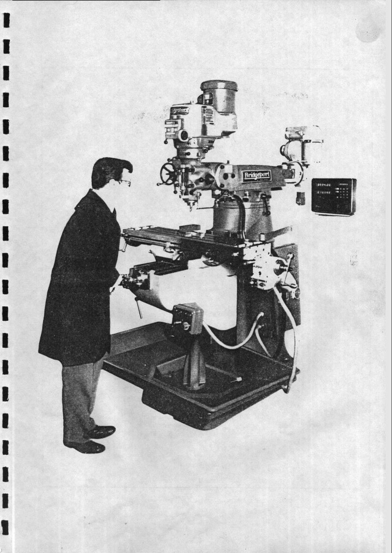
Comprehensive instruction manual for Bridgeport milling machines—an essential workshop reference covering the complete lifecycle of machine setup, operation, and maintenance. The manual begins with practical handling and initial cleaning procedures, then progresses through foundation installation, electrical power configuration, and pre-operation setup. The operations section provides thorough guidance on all control systems across the J-head, 2J2-head, M-head, and E-head models, including spindle speed selection, quill feed operation, and table drive mechanics. A dedicated lubrication section documents service intervals and specifies the correct lubricants for every major assembly, ensuring proper long-term performance. Maintenance procedures address critical adjustments and repairs—backlash correction, belt and brake shoe replacement, balance spring service—with clear instructions for each task. Detailed numbered diagrams illustrate machine assemblies and operating systems, paired with comprehensive parts lists that include component reference numbers for accurate ordering and identification. Technical specifications and performance data for each head type support both routine operation and systematic troubleshooting. This workshop manual serves as the authoritative guide technicians and operators need for reliable Bridgeport milling machine operation and upkeep.
Bridgeport Milling Machine Operator's Manual
1964 operator's manual for Bridgeport milling machines. This comprehensive workshop manual covers setup essentials—uncrating, foundation preparation, machine leveling, and head assembly alignment—along with installation of the long and cross feed assemblies, gib adjustment, and detailed lubrication schedules. It includes full operating instructions for the power feed attachment, measuring attachment, and specialized attachments for J, M, W, R, and C model variants. You'll find cutting speeds and feeds guidance, belt housing assembly details, brake and clutch coverage, dimensional drawings, floor plan diagrams, technical specifications, parts lists, and engineering drawings. An essential reference for operators and technicians maintaining these classic machines.
Bridgeport Milling Machine Operator's Manual
Bridgeport milling machine operator's manual from January 1957, a foundational reference for setup, operation, and day-to-day machine management. Covers essential procedures for machine installation, lubrication schedules, and systematic adjustment of spindle and feed mechanisms. Includes detailed dimensional drawings and floor-plan layouts to guide initial positioning. Step-by-step instructions walk through long and cross feed assembly, mounting procedures for optional attachments across J, M, R, and C model variants, and installation of power feed systems. A practical section on measuring attachments, cutting speeds, and feed rate tables helps operators select correct parameters for different materials and tool configurations. Comprehensive parts lists itemize components for quill housing units, belt housing assemblies, brake and clutch mechanisms, and transmission gear sets—essential for maintenance planning and parts identification. 40 pages of authentic workshop documentation from the manufacturer.
Bridgeport Milling Machines Safety Manual
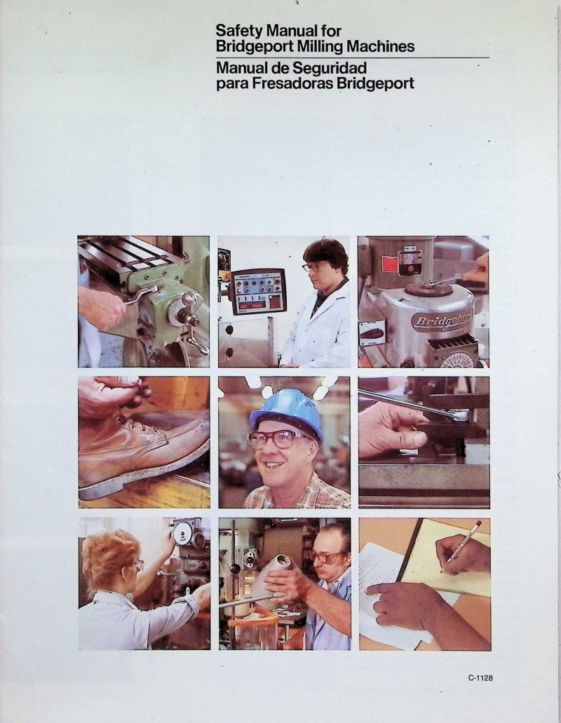
Bilingual safety manual (English/Spanish) for Bridgeport milling machines covering eight essential safety rules with illustrated guidelines. Addresses machine operation requirements, compliance with machine signage and safety documentation, qualified operator instruction, eye and head protection, hazards from moving parts, hair management, and jewelry and clothing precautions. Includes operational procedures, safety test methods, and operator responsibilities. A practical reference for workshop safety compliance and safe machine operation.
Bridgeport Series 1 Ball Screw Retrofit Manual
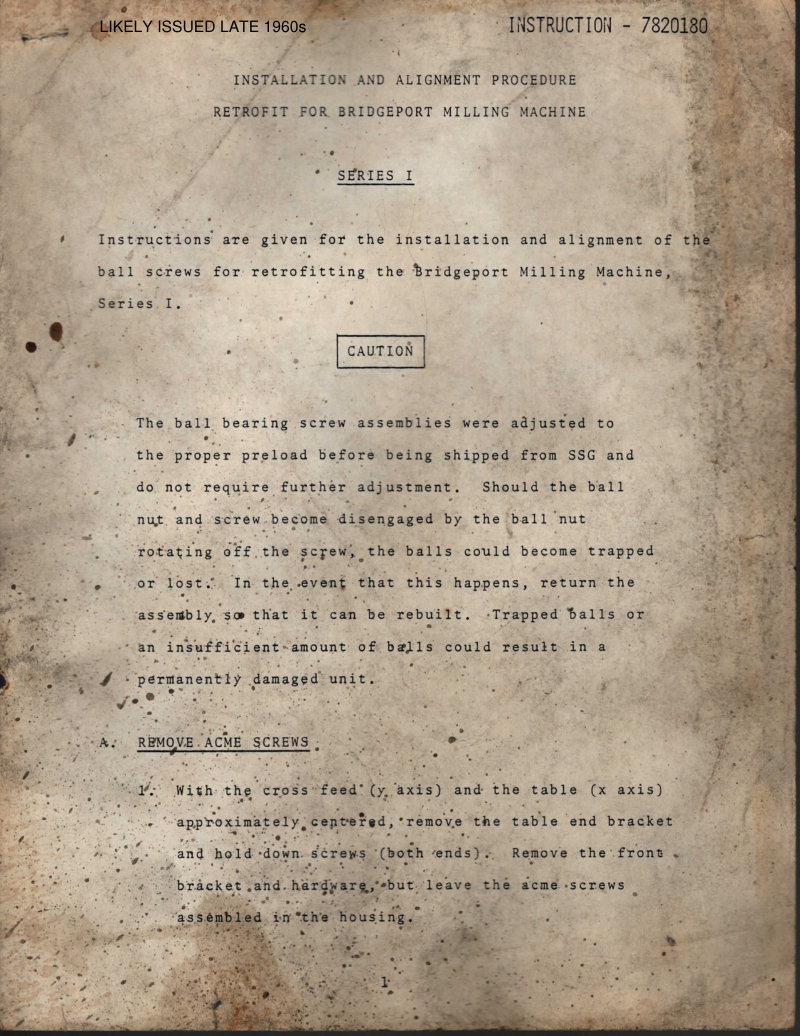
Complete retrofit manual for upgrading Bridgeport Series I milling machines with ball screw assemblies. Details the full conversion process from original ACME screws to precision ball screw systems, including step-by-step removal procedures, assembly instructions for both cross feed (Y axis) and table traverse (X axis) ball screw units, housing installation, and alignment specifications. Addresses critical setup considerations such as ball nut preload adjustment, proper lubrication techniques, and correct oil line routing to ensure smooth machine operation and longevity. References instruction 7820180. Essential reference for machine builders, retrofit technicians, and experienced operators performing in-house upgrades to extend Bridgeport Series I capability and precision.
Bridgeport Series 1 Operator's Manual
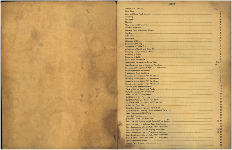
Operator's manual for the Bridgeport Series 1 milling machine, January 1960 edition. This comprehensive workshop manual covers everything needed to set up, operate, and maintain this iconic machine tool. Includes detailed uncrating instructions, foundation preparation, leveling procedures, and head mounting on the overam adapter. Covers lubrication points, inspection routines, and precise head alignment methods. The manual walks through table gib and saddle/knee gib adjustment, proper clamping techniques for table, saddle, and knee assemblies, and procedures for table and saddle removal when required. Details power feed attachment installation, measuring attachment setup, motor mounting, and V-belt adjustment. Provides operating instructions for J and JJ attachments with general speed recommendations and a complete cutting speeds and feeds reference table. Includes extensive parts drawings and illustrated parts lists for J and JJ attachments, Quill housing units, V-belt drive units, back gear transmission assemblies, clutch assemblies, power feed attachments, M and R attachments, shaping and facing attachments, and C attachment. Also contains optical measuring system documentation. Dimensional drawings and floor plan included. An essential service and repair guide for Bridgeport Series 1 operators and maintenance technicians.
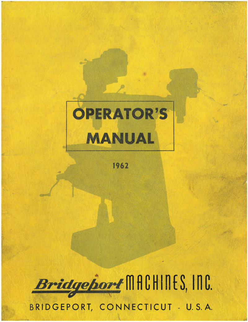
Bridgeport Series 1 Operator's Manual
1962 operator's manual for the Bridgeport Series 1 milling machine — a foundational workshop manual covering everything needed to set up, maintain, and safely operate this classic industrial workhorse. The guide walks through uncrating and initial inspection, foundation placement and leveling procedures to ensure precision alignment, and detailed head mounting instructions. You'll find comprehensive lubrication schedules, table adjustment and clamping procedures, and step-by-step saddle and knee removal when service is needed. Includes assembly instructions for the longitudinal and cross feed mechanisms, power feed attachment installation and operation, and measuring attachment setup. The manual provides dimensional drawings and floor plan layouts for shop planning, detailed parts lists and component drawings for various factory attachments, plus general speed and feed recommendations for common machining operations. An essential reference for operators and shop technicians maintaining or troubleshooting the Series 1.
Bridgeport Series I CNC Operating Manual
Operating manual for the Bridgeport Series I CNC milling, drilling and boring machine. This workshop manual covers operation and programming for BOSS 4.0, 5.0 and 6.0 software versions. Document reference Code No. 1104-0070 (formerly M-128). Includes critical safety documentation regarding protective shields and chemical compatibility between coolant and cutting oil formulations. Published November 1993. Essential troubleshooting and maintenance reference for Series I CNC machine operators and technicians. Table of Contents: - SERIES I CNC DESCRIPTION - Machine - CNC Control - Optional Equipment - OPERATOR'S CONTROLS AND INDICATORS - Machine Control Equipment - Operator's Main Control Panel - Status - Spindle Control Panel - Special Operation's Panel - Optional Equipment - OPERATION IN SETUP - Initial Conditions at Power ON - Positioning Along an Axis - Setting the XY Absolute Zero Location - Tool Length Offset - Tool Length Offset Storage - Tool Diameter Reference - Cutter Diameter Compensation - Turning Power OFF - MANUAL DATA INPUT - Manual Data Input - Loading Program into Storage - Real Time Control - Local Data Input - The Editor - Editor Summary - Text Entry by Terminal Reader - System Reset - AUTOMATIC OPERATION - Normal Operation - Special Conditions - TOOL HOLDERS - General Description - Installation - Random Set Cutting Tools - Preset Cutting Tools - Tightening Fixture
Bridgeport Series I CNC Programming Manual
Bridgeport Series I CNC Programming Manual for BOSS 4.0, BOSS 5.0, and BOSS 6.0 software—the essential workshop reference for setup, operation, and code generation on this versatile milling, drilling, and boring machine. Document Code 1104-0071 (formerly M-129), published July 1993. Covers programming fundamentals, machine configuration, and practical cutting strategies. Includes critical safety guidance on shield materials and compatibility with coolants and cutting oils to protect both operator and equipment during high-speed operations. This manual is indispensable for CNC machinists, tool engineers, and maintenance technicians working with Bridgeport Series I systems in production and job-shop environments. Table of Contents: - SERIES I CNC SPECIFICATIONS - General Description - Features of the Bridgeport Series I CNC - Features of the Bridgeport CNC Control System - Optional Equipment - Leading Data - PROGRAMMING FORMAT SUMMARY - Reference Standards - Letter Addresses - Program Entries - TOOLS AND METHODS CONSIDERATIONS - Cutting Tools - Tool Holders - Machinability - CONTROL TAPE FORMAT DETAILS - The Coordinate Systems - Tape Description - Programming Form - PROGRAM ENTRIES DESCRIPTIONS - Definition Block and Block Delete - Sequence Number (N) - Preparatory Functions (G) - Linear Axis Command (X,Y,Z) - Polar Coordinate Commands - Arc Center Offset Commands (I,J,K) - Feedrate Commands (F) - Spindle Speed Commands (S) - Tool Select Commands (T) - Miscellaneous Function Commands (M) - End of Block Command (CR) - Developing a Continuous Path Program - REPETITIVE PROGRAMMING - Looping - Macro Sub-routines - Repetitive Programming Examples - PROGRAMMING EXAMPLE - Engineering - Programming - CUTTER PATH TRANSFORMATION - Rotation - Scaling - Roles for Transformation
Bridgeport Series I EZ TRAK Installation & Maintenance Manual
Complete installation and maintenance manual for the Bridgeport Series I EZ TRAK machining center (Code No. 1104-2900, April 2000 Rev. E). This workshop manual provides essential guidance on setup, routine maintenance, and component replacement procedures. Safety documentation covers the polycarbonate LEXAN and KODAR PETG copolyester chip and coolant shields, with critical specifications for safe operation. Detailed sections address electrical cabinet assembly, component identification, and the Axis Motion Control system architecture. Includes comprehensive parts breakdown for troubleshooting and parts sourcing. Indispensable reference for shop floor technicians and machine operators performing preventive maintenance or component service on this CNC milling system.
Bridgeport Series I M-105 Installation Manual
Installation, operation and maintenance manual for the Bridgeport Series I M-105 milling machine. This comprehensive workshop manual covers machine setup and foundation requirements, including dimensional drawings, floor plan specifications, and proper leveling procedures. Details long and cross feed assembly, saddle and knee adjustment mechanisms, and table removal procedures. Includes lubrication schedules and schematic diagrams essential for routine maintenance and inspection. Explains head mounting on the overarm adapter, belt placement, and motor installation. Operating instructions cover the U, J and M attachments with photographs and speed recommendations for each. Features a complete parts list with exploded views for the BR turret milling machine, plus guidance on power feed and measuring attachment installation. An essential service reference for technicians maintaining or troubleshooting this classic industrial milling machine.
Bridgeport Series I Milling Machine Manual
Installation, operation, and maintenance manual for the Bridgeport Series I turret milling machine model BR2J. This workshop manual covers machine and milling head specifications, uncrating and site preparation including cleaning, lifting, and placement, machine leveling and mounting procedures, handle installation, power supply connection and motor setup, lubrication schedules, head alignment and calibration, table and saddle adjustment techniques, workholding and clamping procedures, vari-drive attachment mounting and configuration, complete operating instructions for spindle brake operation and feed control management, ram positioning protocols, motor removal and belt replacement procedures, and detailed parts identification with exploded diagrams for assembly reference and troubleshooting.
Bridgeport Series I Milling Machine Manual
Complete installation, operation and maintenance manual for the Bridgeport Series I milling machine. This workshop manual covers setup procedures, daily operation, routine maintenance schedules, and troubleshooting guidance for reliable machine performance. Manual designation M-105B, published August 1976 by Bridgeport Machines Division of Textron Inc. Essential reference for operators and technicians maintaining this classic milling machine. Table of Contents: - Machine Specifications - Milling Head Specifications - Uncrating - Shortages - Cleaning - Lifting Machine - Placing on Solid Foundation - Leveling Machine - Mounting Head on Overarm Adapter - Handles - Connecting Power Supply - Lubrication - Alignment of Head - Adjustment of Table Gib - Adjustment of Saddle and Knee Gibs - Clamping Table, Saddle and Knee - Removing Table - Removing Saddle - Mounting Vari-Drive Attachment to Ram Adapter - Lubrication - Operating Instructions - Spindle Brake - High-Low Range Switch - Hi-Neutral-Lo Lever - Power Feed Transmission Engagement Crank - Quill Feed Selector - Feed Reversing Knob - Manual Feed - Feed Control Lever - Quill Feed Handle - Quill Stop - Micrometer Adjusting Nut - Position of Ram - Operating Instructions - Removing Motor - Changing Vari-Drive Belt - Changing Timing Belt - General Speed Recommendations - Parts Identification - Basic Machine - Leadscrew Assembly - J Head Top Housing - J Head - 2J Head Top Housing - 2J Head Back Gear
Bridgeport Series II N/C Installation Manual
Installation, operation and maintenance manual for Bridgeport Series II N/C milling machines equipped with Bridgeport Controls. Covers models XNC2BC2CP and XNC2BC3CP, serial numbers 430 and above. This 246-page workshop manual includes complete installation procedures, detailed operational guidelines, and comprehensive maintenance instructions. Parts I and II revised January 1974. Essential reference for setup, daily operation, troubleshooting, and upkeep of these numerically controlled vertical mills. Table of Contents: - INTRODUCTION - General Description - Leading Particulars - Optional Equipment - PREPARATION FOR USE - Uncrating - Lifting the Machine - Shortages - Cleaning - Installation - Placing Powered Knee in Service - Lubrication - Alignment - MACHINE DETAILS - Introduction - Features
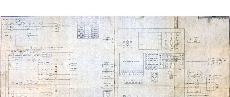
Bridgeport Series II Schematic
Complete electrical wiring schematic for the Bridgeport Series II milling machine. This single-page technical drawing provides essential workshop reference material, detailing circuit diagrams, component layout, relay configurations, and full electrical specifications. Includes a comprehensive parts list and technical notes for troubleshooting, maintenance, and electrical system repair. Essential for machine shop technicians and equipment maintenance personnel working on Series II installations.
Bridgeport Turret Miller Model J Operators Manual
Operators manual for the Bridgeport Turret Miller Model J Milling Attachment. This comprehensive workshop manual covers setup, operation, and maintenance of the turret milling head and all standard accessories. Includes dimensional drawings, floor plan layout, feed assembly construction and installation, detailed lubrication schedules, inspection checkpoints, spindle and table alignment procedures, saddle and table adjustment techniques, workholding and clamping methods, power feed installation and full operating instructions, optical measuring attachment usage, machinist's cutting speeds and feeds reference table, and complete parts lists for the main milling unit, brake and clutch assembly, V-belt drive system, and precision optical measuring system. An essential service reference for operators and technicians responsible for setup, troubleshooting, and routine maintenance on this classic production mill. Table of Contents: - Dimensional Drawing - Floor Plan - Long and Cross Feed Assembly - Ncrating - Shortages - Cleaning - Placing on Solid Foundation - Leveling Machines - Mounting Head on Overarm Adapter - Handles - Lubrication - Inspection - Alignment of Head - Lubrication Drawing - Adjustment of Table Gib - Adjustment of Saddle and Knee Gibs - Cleaning Table, Saddle and Knee - Removing of Table - Removing of Saddle - Power Feed Attachment - Instructions for Installing Power Feed - Installation and Use of Measuring Attachment - Descriptive Photograph of Model "M" Attachment - Mounting Motor on Attachment - Placing and Adjusting Belts - Operating Instruction of "J" Attachment - Operating Instruction of "J" Attachment - Operating Instruction of "J" Attachment - Operating Instruction of "J" Attachment - General Speed Recommendations - Table of Cutting Speeds and Feeds - Parts Drawing on "J" Attachment - Parts List on "J" Attachment - Quill Housing Unit Parts List - Quill Unit Parts List (Serial "J" 1200) - Quill Unit Parts List (Serial J 1200 and Up) - V Belt Unit Parts List - Back Gear Transmission Unit Parts List - Quill Pinion and Overload Clutch Assembly Parts List - Feed Transmission Unit Parts List - No. 4 Belt Housing - Brake and Clutch Unit Parts List - Parts List and Drawing on BR Turret Milling Machine - Parts List and List on Power Feed Attachment - Parts Drawing and List on Model "M" Attachments - Parts Drawing and List on Shaping Attachment - Parts Drawing and List on Cherrying Attachment - Parts Drawing and List on Model "R" Attachment - Parts List and Drawing on Model "C" Attachment - Optical Measuring System - Optical Parts Drawing - Optical Parts List
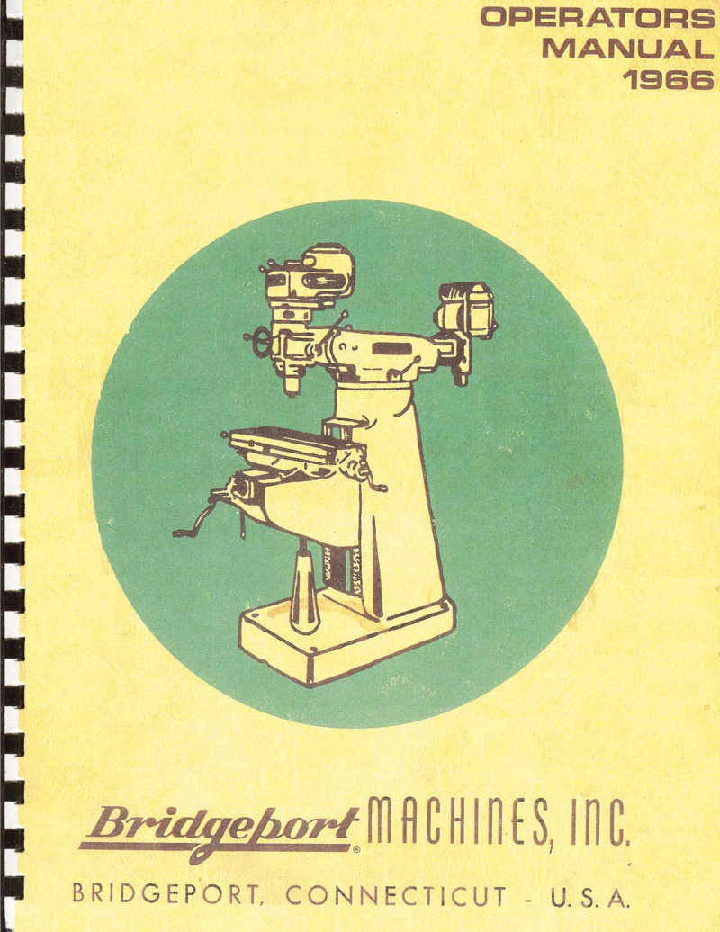
Bridgeport Turret Miller Model J Operators Manual
1966 operators manual for the Bridgeport Turret Milling Machine with Model J Milling Attachment. This comprehensive workshop manual covers machine setup from uncrating and foundation placement through detailed assembly and adjustment procedures. Includes dimensional drawings and floor plan layout, lugs and cross feed assembly preparation, cleaning and inspection protocols, mounting the head on overarm adapter, and systematic leveling and alignment techniques. Detailed sections address lubrication schedules, table gib adjustment, saddle and knee gib adjustment, and proper clamping procedures for table, saddle, and knee components. Covers removal and reinstallation of table and saddle, installation of the power feed attachment with motor mounting and belt adjustment and tensioning. Operating instructions specific to the J attachment detail general speed recommendations and provide a comprehensive table of cutting speeds and feeds for various materials and operations. Extensive parts drawings and parts lists included for the J attachment, BR turret milling machine, power feed attachments, M attachments, and optical measuring system. Essential reference for setup, operation, maintenance, and troubleshooting of this classic industrial milling machine.
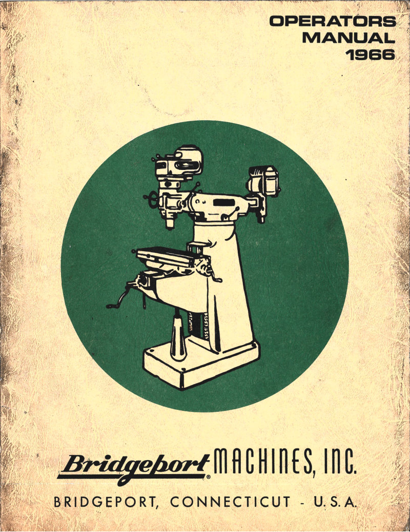
Bridgeport Turret Miller Operators Manual
1966 operators manual for the Bridgeport Turret Miller equipped with Model J milling attachment. This workshop manual provides complete guidance on machine setup, uncrating, foundation preparation, and leveling. Covers assembly of the longitudinal and cross feed mechanisms, head mounting on the overarm adapter, and proper handling of all mechanical components. Includes lubrication schedules, adjustment procedures for table and knee gibs, and clamping techniques for table, saddle, and knee assemblies. Details power feed attachment installation, measuring attachment setup, and optical measuring system integration. Features operating instructions specific to the J attachment with recommended speeds and feeds for milling operations. Contains dimensional drawings, floor plan layouts, motor mounting guidance, and belt placement and adjustment procedures. Provides parts drawings and parts lists for the J attachment, BR turret milling machine, power feed attachments, M, boring, shaping, R, and C attachments, and accessories. Includes descriptive photography and inspection and alignment procedures to ensure optimal machine performance.
Bridgeport Turret Milling Machine Owner's Manual
Operator's manual for Bridgeport Turret Milling Machine with Master Milling Unit. Covers uncrating, handling, and mounting procedures, belt adjustment, and machine operation. Detailed guidance on setup and routine maintenance ensures reliable performance of the 15-inch diameter turret with 5-inch overarm. Machine specifications include 1500 lbs weight, 9x32 inch table, 20-inch longitudinal feed, 9-inch cross feed, and 16-inch vertical knee feed. Features keyed overarm with worm wheel control for precise angular settings, anti-friction bearings throughout, and a large 3.25-inch diameter graduated dial for fine adjustments. Essential reference for operators and shop technicians working with this classic precision milling machine.
Bridgeport Turret Milling Machine Owner's Manual
1962 operator's manual for the Bridgeport turret milling machine—a comprehensive workshop reference covering setup, operation, and maintenance of this versatile precision machine tool. The manual includes dimensional drawings and floor-plan guidance for installation, detailed uncrating and foundation preparation procedures, precise leveling and head-mounting techniques, and systematic inspection and alignment protocols essential for accurate work. Coverage extends to lubrication schedules, table adjustments, clamping methods, and power-feed installation and troubleshooting. Technical sections address cutting speeds and feeds for different materials, quill and belt unit operation, transmission systems, brake and clutch mechanisms, turret milling attachments, shaping and shearing work-head configurations, R and C model attachments, and optical measuring systems. The manual also provides extensive parts lists and component identification for service and replacement, making it an indispensable reference for operators and technicians maintaining or restoring this classic Bridgeport machine.
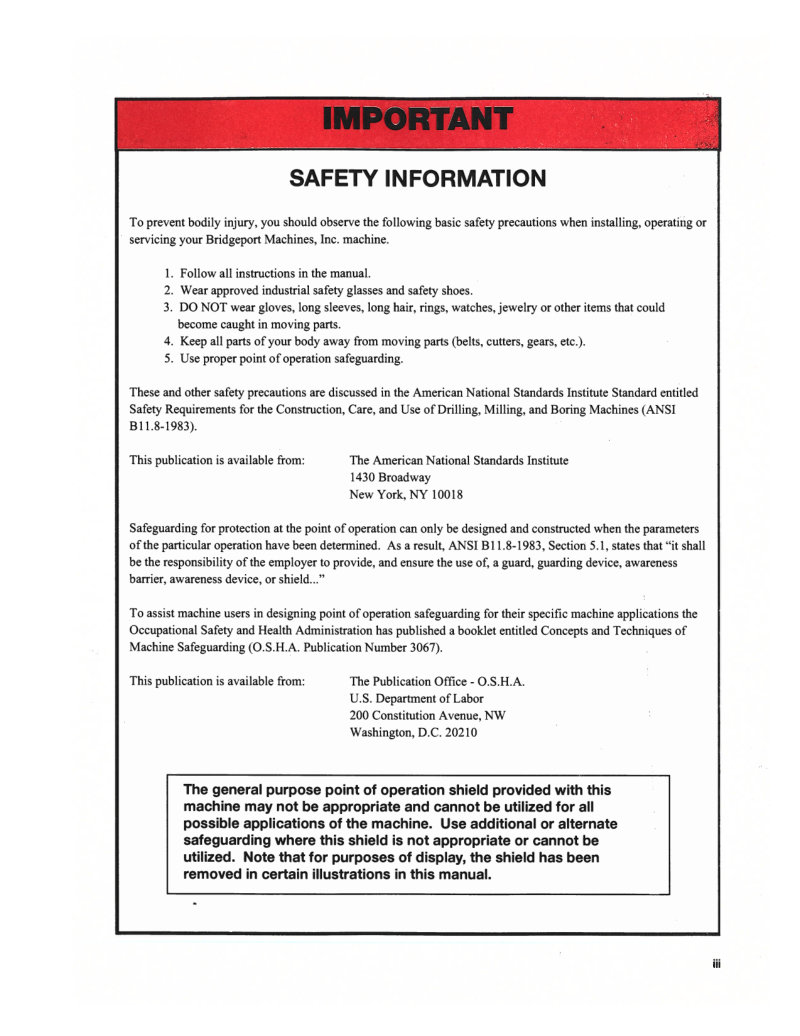
EZTrak Version 7 Programming and Operating Manual
Programming and operating manual for EZTRAK Control Operating Software Version 7.00, the control software for Bridgeport CNC machines. This workshop manual covers setup, programming, and day-to-day operation of the EZTrak system, with detailed safety guidance meeting ANSI B11.8-1983 standards for drilling, milling, and boring machines. Published by Bridgeport Machines, Inc., Code No. 1104-3804, July 2002. An essential reference for machine operators and technicians working with EZTrak Version 7 control systems.
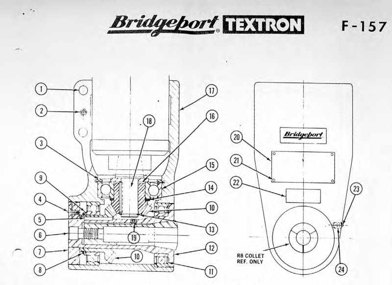
F-157 Right Angle Milling Head Parts List
Parts diagram and detailed parts list for the Bridgeport Textron F-157 right angle milling head (J-head) attachment. Covers 24 indexed components with part numbers, descriptions, and cross-referenced assembly drawings to support repair, maintenance, and parts identification work. Original publication March 1979. Essential reference for workshop technicians maintaining or servicing this specialized milling head configuration.
M-105H Milling Machine Installation Manual
Complete installation, operation and maintenance manual for the Bridgeport Series I M-105H milling machine, including the turret miller model BR2J. This workshop manual provides comprehensive guidance on safe setup, daily operation, and long-term upkeep of this industrial milling system. Covers essential safety precautions and operational warnings to ensure proper use and equipment longevity. An indispensable reference for machinists, maintenance technicians, and shop managers responsible for this equipment.
M-135 Series IIA NC Programming Manual
Programming manual for the Bridgeport M-135 Series IIA NC milling, drilling and boring machine (serial number 1367 and up). This workshop manual covers the complete programming framework for numerical control operation, including machine specifications, programming format summary, control tape format standards, and detailed program entry descriptions. The guide addresses practical tool and methods considerations essential for productive setup and execution. Features seven worked programming examples that walk through real-world scenarios, plus techniques for efficient repetitive programming sequences. Includes all necessary reference data for operators and programmers working with this CNC equipment. October 1977 edition from Bridgeport Machines Division of Textron Inc.
M-135 Series IIA Programming Manual
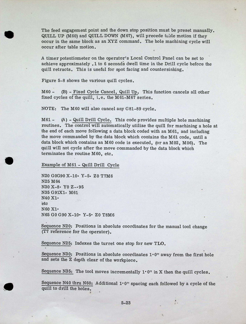
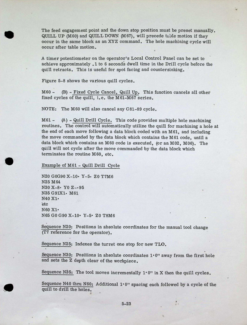
Programming manual for the Bridgeport M-135 Series IIA NC milling, drilling and boring machine. This repair and maintenance reference covers essential programming sequences for computer numerical control operations. Pages 1–3 detail quill cycles controlled by M60–M67 miscellaneous function codes, encompassing drill cycle, drill with dwell, bore, and tap operations. Each cycle breaks down the key phases: rapid approach, controlled feed advancement, and rapid retract. The manual includes worked examples of M61 quill drill cycle sequences and thorough explanations of the auxiliary function codes (M60, M64, M67) that govern these operations, plus carriage return (CR) end-of-block command syntax essential for proper machine execution.
Model 9 & 12 Turret Milling Machine Manual
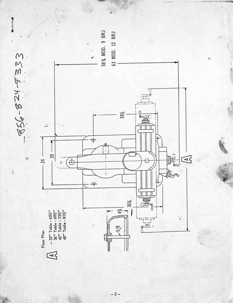
Operations and parts manual for Bridgeport Model 9 and Model 12 turret milling machines. Covers floor plan specifications for table sizes ranging from 32" to 48", assembly drawings that detail the longitudinal and cross feed assemblies with exploded component views, and startup procedures including uncrating, damage inspection, parts verification, cleaning, machine placement on solid foundation, and leveling. This workshop manual provides the technical guidance needed for initial setup and ongoing operation of these classic precision milling machines.
Model J Milling Attachment Operator's Manual
Operator's manual for the Bridgeport Model J milling attachment, issued January 1957. This workshop manual provides complete guidance on setup, operation, and maintenance of the Model J head and its variants (J, JJ, and M attachments). Content covers uncrating and machine placement, leveling and alignment procedures, head mounting on the overarm adapter, lubrication schedules, table and saddle gib adjustment, clamping mechanisms, and removal procedures. Includes detailed instructions for the long cross feed assembly, power feed attachment operation, and inspection protocols. The manual features comprehensive parts lists, technical drawings, and practical cutting speed and feed rate recommendations for various milling operations. An essential reference for operators and maintenance technicians working with classic Bridgeport turret milling equipment.
PowerPath-15 CNC Lathe Installation Manual
Installation and maintenance manual for the ROMI PowerPath-15 CNC lathe equipped with Bridgeport DX-32 control system. Document R68654D is a comprehensive workshop reference covering setup procedures, site preparation requirements, electrical wiring and grounding methods, transport logistics, machine cleaning and lubrication schedules, hydraulic system operation, securing and leveling procedures, spindle configuration, chuck jaw systems, and component specifications for power chucks and hydraulic cylinders. This manual provides technicians and operators with detailed guidance for initial commissioning, ongoing maintenance protocols, and parts identification necessary for reliable operation. Table of Contents: - 1. INSTALLATION MANUAL (R67516B) - Initial Steps - Recommended Installation Conditions - Electrical Installation - Grounding - Transportation - Cleaning - Lubrication - Hydraulic unit - Anchoring - Floor Space Requirede and Foundation Plant - Machine Layout - Leveling - Tooling System - Spindle Nose - Soft Jaws - Work Layout - Power Chuck and Hydraulic Cylinder - 2. MAINTENANCE MANUAL (R66617A) - Introduction - Main Characteristics - Standard Equipments - Accessories - Safety Precautions - Basic Operating Practice - Care and Warnings Before Operating the Machine - Routine Inspection - Warming the Machine - Set up for Machining - Operation - To Interrupt Machining Operation - After Finishing a Job - Preparation for Maintenance - Maintenance Work
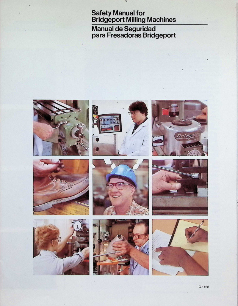
Safety Manual for Bridgeport Milling Machines
Safety manual for Bridgeport milling machines with bilingual English-Spanish content. Covers essential safety requirements including personal protective equipment (safety glasses, hard hat), hazard awareness for moving parts, machine operation procedures, and pre-operation setup. Features eight core safety rules with instructional photographs and a safety test on pages 12–13. The manual emphasizes the importance of reading the operator's manual and completing qualified instruction before operating the machine.
Series 1110 Control-Path Tracer Valves Service Manual
Service manual for Bridgeport True-Trace Series 1110 Control-Path Tracer Valves, an automatic 360/3D tracing system designed for precision path control. Document dated October 1, 1981, manual number D-510C. This comprehensive 156-page workshop manual covers detailed technical specifications, assembly diagrams, and step-by-step service procedures for maintaining and troubleshooting the tracer valve assembly, along with component identification, operational parameters, and repair guidelines for technicians. Table of Contents: - TRACER VALVE IDENTIFICATION - NOTES ON INSTALLATION - LUBRICATION & START-UP - DESCRIPTION OF CONTROLS - TRACER VALVE ADJUSTMENTS - TECHNICAL BULLETIN - PARTS LIST IDENTIFICATION - AIR IN HYDRAULIC SYSTEM - PLUMBING DIAGRAM & SCHEMATIC - TROUBLE-SHOOTING GUIDE - FIELD SERVICE BULLETINS
Series I CNC Maintenance Manual (BOSS 3)
Maintenance manual for the Bridgeport Series I CNC milling, drilling and boring machine with BOSS 3 control system. Published October 1978 by Bridgeport Machines, Inc. This comprehensive workshop manual covers preventive maintenance procedures, troubleshooting, component inspection, and operational safeguards for Series I equipment. Includes critical safety documentation regarding point of operation guarding and references to applicable machinery protection standards. An essential reference for technicians performing routine service, adjustments, and diagnosis of Series I CNC machines equipped with BOSS 3 controls. Table of Contents: - THEORY OF OPERATION - The XY Step Motor Drive - Knee Drive - Lubrication - The Z Axis Drive - The Milling, Drilling and Boring Head - Specifications - POWER SUBSYSTEM - Power Distribution - Regulated Power Supply Adjustment Procedure - CONTROL - System Description - Logic Boards - Axis Drive System - BASE ASSEMBLY ADJUSTMENT AND MAINTENANCE - X and Y Axis Counters - X and Y Axis Drive Motors - X and Y Axis Ball Screws - Limit Switch Replacement - Table and Saddle Removal - Knee Drive Manual - Lubrication - X and Y Axis Gibs - SERIES I CNC HEAD ADJUSTMENT AND MAINTENANCE - Lubrication - Power Transmission - Quill and Spindle - Quill Limit Switches (Rigid Ram or V-Ram Machine) - Alignment of Quill Housing Assembly to Drive Motor Housing Assembly - SCHEMATICS AND PARTS LIST - Schematic Drawings - Parts Lists
Series I CNC Mill Installation Manual
Installation manual for the Bridgeport Series I CNC milling machine covering the complete setup process from delivery through first-run operation. Provides step-by-step guidance on receiving and unloading the shipment, safe lifting and positioning, site preparation, machine cleaning and precise leveling, lubrication procedures, electrical power connection and wiring, manual operation startup sequences, and full system checkout protocols. Includes detailed instructions for critical tasks such as spindle trammeling to ensure accurate boring and drilling, axis drive system operation for coordinated milling movements, and control equipment setup for CNC function. Features technical figures illustrating overall machine dimensions, lifting procedures and rigging points, machine base layout and foundation requirements, lubrication system diagrams, electrical and control equipment enclosure configurations, and tape reader installation and setup options. An essential reference for machine installation technicians and operators preparing a Bridgeport Series I for production work. Table of Contents: - SAFETY NOTICE - RECEIVING THE SHIPMENT - Weights and Measures - Unloading the Shipment - Shortages and Damage - LIFTING THE MACHINE - Fork Lift - Removing the Machine Skid - PREPARATION OF THE MACHINE LOCATION - Foundation and Clearances - Electrical Service - PREPARATION FOR OPERATION - Cleaning the Machine - Leveling the Machine - Lubrication - Inspection of Power Equipment Enclosure - Inspection of the Control Equipment Enclosure - STARTUP TO MANUAL OPERATION - Connecting Electrical Power - Electrical Power Distribution - The Operating Manual - The Axis Drive System - Spindle Trammeling - CHECKOUT - Terminal Connection - The Operating Manual - Test Tapes - The Programming Manual
Series I CNC Programming Manual
Programming manual for the Bridgeport Series I CNC milling, drilling and boring machine equipped with BOSS 4.0, BOSS 5.0, or BOSS 6.0 control software. Published January 1981. This comprehensive workshop manual covers Series I CNC specifications, programming format summary, practical tools and methods guidance, control tape format details, and complete program entry descriptions. Covers definition blocks, sequence numbers, preparatory functions, linear axis commands, arc center offset commands, feedrate commands, spindle speed commands, tool select commands, miscellaneous function commands, end of block protocols, and continuous path program development techniques. Essential reference for operators and programmers working with Bridgeport Series I CNC equipment. Table of Contents: - LIST OF ILLUSTRATIONS - SAFETY NOTICE - SERIES I CNC SPECIFICATIONS - General Description - Features of Bridgeport Series I CNC - Features of Bridgeport CNC Control System - Optional Equipment - Loading Data - PROGRAMMING FORMAT SUMMARY - Reference Standards - Letter Addresses - Program Entries - TOOLS AND METHODS CONSIDERATIONS - Cutting Tool - Tool Holders - Machinability - CONTROL TAPE FORMAT DETAILS - The Coordinate Systems - Tape Description - Programming Form - PROGRAM ENTRIES DESCRIPTIONS - Definition Block and Block Delete - Sequence Number (N) - Preparatory Functions (G) - Linear Axis Command (X,Y,Z) - Arc Center Offset Commands (I,J,K) - Feedrate Commands (F) - Spindle Speed Commands (S) - Tool Select Commands (T) - Miscellaneous Function Commands (M) - End of Block Command (CR) - Developing of Continuous Path Program
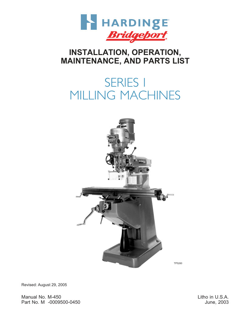
Series I Milling Machine Service Manual
Comprehensive service and workshop manual for Bridgeport Series I milling machines. Covers detailed installation procedures, operating instructions, and maintenance guidelines. Includes a complete parts list for ordering genuine replacement components, safety precautions aligned with ANSI B11.8-1983 standards, and point-of-operation safeguarding requirements per OSHA regulations. Essential reference for operators and technicians performing routine maintenance or troubleshooting. Table of Contents: - CHAPTER 1 - INSTALLATION - Uncrating - Shortages - Cleaning - Installation - Handles - Positioning Head Upright - Handling - Lifting the Machine - Foundation - Machine - Tightening Sequence - Placing on Solid Foundation - Leveling Machine - Machine Power Supply - Connecting the Power Supply - Lubrication - Initial Settings - Head Controls - Alignment of Head for Fine Work - Tightening Sequence - Lubrication - CHAPTER 2 - OPERATION - Head Controls - High-Low Range Switch - Variable Speed Dial - Spindle Brake - Quill Feed Selector - Quill Stop Knob - Micrometer Nut - Feed Reverse Knob - Manual Feed Handwheel - Feed Control Lever - Feed Control Overload Clutch - Quill - Spindle - Quill Lock - Quill Feed Handle - Power Feed Transmission Engagement Crank - Hi-Neutral-Lo Lever - Speed Change Handwheel - Motor - Drawbar
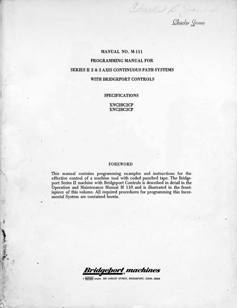
Series II Continuous Path Programming Manual
Programming manual for the Bridgeport Series II continuous path milling systems covering 2 and 3 axis programming with Bridgeport control. This workshop manual provides complete part programming instructions, including setup sheets for both decimal and non-decimal word formats, miscellaneous machine functions, and specialized Z-axis cycles. Covers tape codes and formats used in the control system, as well as foundational point-to-point programming with axis nomenclature and workpiece mounting techniques. Includes practical drill cycle and turret depth stop examples to guide setup and execution. The continuous path contour programming section addresses essential machining topics such as end mill diameter compensation, climb milling strategies, corner treatments, scallop height control, cutter deflection analysis, radius and circular interpolation, feedrate coding and automatic offset correction, and speed selection. Provides detailed information on tape read timing, dwell periods, tolerance and accuracy considerations, and the geometric and trigonometric principles necessary for effective part design. Also features a computer-assisted part programming section explaining postprocessor vocabulary and implementation notes for users programming offline. Essential reference for technicians and programmers operating Bridgeport Series II systems.
Series II Turret Miller Operation Manual
Comprehensive operation manual for the Bridgeport Series II Turret Miller, covering installation, operation, and maintenance procedures for this precision milling machine. Includes detailed guidance on machine setup, safe operating practices, and routine maintenance. Features the Pride In Performance (PIP) inspection certification program with quality assurance standards and technical support information from Bridgeport Machines Division of Textron Inc. An essential reference for operators and technicians responsible for setup, daily operation, and preventive maintenance of Series II turret milling equipment.
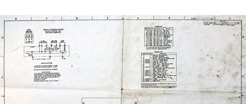
Series II Velocity Control Unit Schematic
Wiring diagram and electrical schematic for the Bridgeport Series II Standard Machine Velocity Control Unit, dated June 16, 1955. This service manual provides complete technical documentation for understanding, troubleshooting, and maintaining the velocity control system. It includes a terminal block diagram with all connection points, detailed control unit specifications, a comprehensive parts list with component references for identification and ordering, and a full electrical schematic showing all interconnections and circuit paths. Essential reference material for technicians performing repair, maintenance, or diagnostic work on Series II machines equipped with velocity control systems.
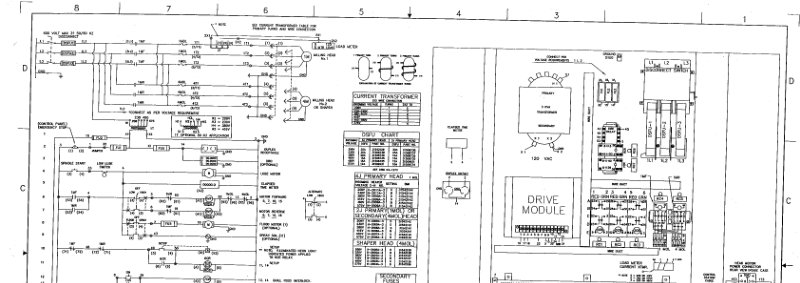
Series II Wiring Diagram - Two Heads/All Options
Complete wiring diagrams for the Bridgeport Series II milling machine equipped with dual head configuration and all available options. This technical documentation spans three detailed schematic pages mapping the entire electrical system: primary and secondary transformer specifications rated at 3 kVA, control station layouts, drive module connections, and 600V three-phase AC power distribution. The diagrams include comprehensive wire color coding references, component identification charts for DSFU and current transformer units, disconnect switch configurations for safe isolation, and terminal connection pinouts for secondary control circuits. Essential for troubleshooting, repair, and system reconfiguration. Drawing number 79-3620.
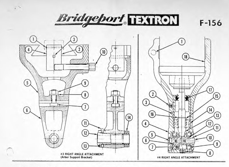
Textron F-156 Right Angle Attachment Parts List
Parts list and assembly diagrams for the Textron F-156 right angle attachment, covering models #3 (Arbor Support Bracket) and #4. Features detailed exploded views with numbered component callouts, specifications for fasteners, bearings, collets, gears, and assembly hardware. Original Bridgeport documentation from March 1979. Essential reference for identifying replacement parts, assembly sequences, and component specifications when servicing or maintaining these precision machine tool attachments.
Tormax 13-5 16-5 Installation Manual
Installation and maintenance manual for Bridgeport Tormax 13-5 and Tormax 16-5 machine tools. This workshop manual provides comprehensive guidance on safe setup and operation, including pre-operation safety precautions, routine machine inspection, proper warm-up procedures, and step-by-step operating instructions. Covers essential maintenance tasks, foundation planning and leveling requirements, and detailed explanations of all major assemblies: headstock operation, thread and feed gearbox control, apron functions, saddle adjustment, tailstock positioning, and camlock spindle nose chuck installation. Includes critical safety plate location information and practical care guidelines to keep your machine running reliably. Whether you're setting up a new installation or performing routine maintenance work, this manual addresses both initial commissioning and ongoing upkeep of these precision lathes.
Turret Miller Model J Attachment Operator's Manual
Operator's manual for the Bridgeport Turret Miller Model J Milling Attachment. This 43-page workshop manual covers essential setup and operation, including dimensional drawings, floor plan requirements, uncrating and placement, machine leveling, mounting, and spindle alignment. You'll find detailed lubrication schedules, adjustment procedures for table changes, and instructions for integrating the power feed and measuring attachments. The manual also provides cutting speed recommendations, operating procedures specific to Model J turret operations, comprehensive parts lists, and guidance on optional shaping, cherrying, R, and C model attachments. Published by Bridgeport Machines (Textron division), this service document is essential for anyone setting up, operating, or maintaining this classic milling machine attachment.
Variable Speed Drive Operator's Manual
Operator's manual for the Bridgeport Variable Speed Drive attachment. This workshop manual covers everything needed to install and operate the unit on your Bridgeport milling machine, including step-by-step assembly instructions for mounting to the ram adapter, proper lubrication procedures to maintain smooth operation, and detailed operating guidelines. You'll find comprehensive coverage of spindle brake function, the high-low range switch, the hi-neutral-lo lever, power feed transmission settings, quill feed selector operation, feed reversing techniques, and manual feed control adjustment. The manual also walks through critical maintenance tasks: quill stop and lock adjustment, micrometer calibration, motor removal procedures, vari-drive belt replacement, and timing belt service. A complete parts list and assembly drawing #21-200 are included to help you identify components and understand the drive system layout. This is the essential troubleshooting and maintenance resource for keeping your Variable Speed Drive running reliably.
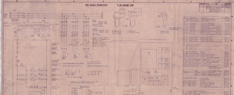
WD162 D Electrical Wiring Schematic
Electrical wiring schematic for the Bridgeport WD162 D milling machine. This third-angle projection technical drawing shows the complete circuit layout with all component connections and control system routing. The diagram details motor circuits, selector switch configurations, and electrical specifications needed for troubleshooting, maintenance, and repair. Annotated notes throughout help technicians and operators understand circuit operation and locate components during service.