GLEASON - Service Manuals
5 manuals available for download
GLEASON has engineered precision machine tools for decades, earning trust across manufacturing and tooling operations worldwide. Our comprehensive technical documentation library includes service manuals, repair guides, and user manuals covering generators, testers, and sharpening equipment—all available as instant PDF downloads. Whether you need a workshop manual for routine maintenance, troubleshooting guidance, or detailed parts lists for your equipment, GLEASON documentation provides the technical clarity professionals demand. Access owner's manuals and maintenance guides designed to keep your machinery running at peak performance.
3 inch Straight Bevel Gear Generator Operating Manual
Operating manual for the 3 inch Straight Bevel Gear Generator, Part No. G3W-775B, covering machines Serial No. 12391 and later. Published by Gleason Works in 1939, this workshop manual provides comprehensive guidance on operating and maintaining this precision gear-cutting machine. The manual opens with essential reference material including drive system descriptions, lubrication schedules, general machine information, and detailed cutting data for various gear configurations. The core procedure sections walk through both rough cutting and finish cutting operations for gears and pinions, laying out 20 critical setup steps in sequence. Setup covers feed cam adjustment, work head positioning, segment arm alignment, crown gear mesh calibration, feed depth settings, tool slide angle configuration, tool speed and feed gear changes, automatic stop positioning, and machine startup sequences. Technicians will find this service manual invaluable for understanding the machine's capabilities and ensuring repeatable, precision gear production. Table of Contents: - Description of Drive - Lubrication - General Information - Data for Cutting - Change Feed and Generating Cams - Set Work Head to Center Position - Put on Segment Arm and Segment and Set to Pitch Angle - Set Work Head to Root Angle - Put Crown Gear and Segment in Mesh - Set Crown Gear Spring Bracket - Set Roll of Cradle - Put on Index Plate - Set Index Trip Dog - Set Depth of Feed - Set Tool Slide Arms to Tooth Angle - Set Tools to Gages - Place Arbor in Spindle - Set Length of Stroke - Set Position of Tools - Put on Tool Speed Change Gears - Put on Feed Change Gears - Set Automatic Stop - Set Position of Trip Cam - Start Machine and Rough Cut Gear or Pinion - Change Feed and Generating Cams - Set Work Head to Center Position - Put on Segment Arm and Segment and Set to Pitch Angle - Set Work Head to Root Angle
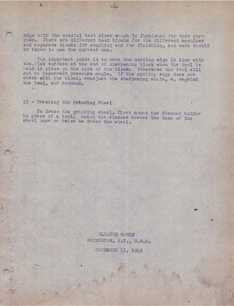
No. 12 Generator Tool Sharpener Operating Instructions
Operating instructions for the Gleason No. 12 Generator Tool Sharpener, a wet-type grinding machine designed for precision tool maintenance and sharpening. This workshop manual covers essential setup procedures including machine placement, removal of rust preventative coating, electric motor connection, and lubrication of all working parts. It specifies the grinding wheel (7-inch diameter flaring cup wheel, 2-inch thickness, 1 1/4-inch arbor hole) and coolant preparation for optimal grinding performance. The guide provides comprehensive instruction on tool holder configuration with its double swivel pivot arrangement, proper tool clamping techniques, wheel truing and adjustment, and step-by-step machine operation. It includes positioning angles for the tool holder when sharpening various tool types and practical techniques for achieving correct cutting geometry, along with tool inspection procedures to verify sharpening results. A complete service reference for operators and maintenance personnel.
No. 446 and 447 Angular Testers - Safety Instructions
Safety instructions and guarding procedures for the Gleason No. 446 angular hand rolling and power tester and Gleason No. 447 angular tester. This workshop manual covers comprehensive safeguarding requirements including point-of-operation guard design, motor compartment door interlocks, limit switches, solenoid locks, and zero-speed switches essential for safe machine operation. The service manual details electrical schematics for guard interlocking systems and safety arrangements configured for 90-degree shaft angle gears, low shaft angle gears, and spur gears. Includes reference photographs and full electrical circuit diagrams to guide proper installation and maintenance of safety mechanisms.
No. 455 Generator Tool Sharpener - Guarding
Safety and guarding guidelines for the Gleason No. 455 Generator Tool Sharpener. This workshop manual addresses the operational safety considerations specific to this fully manual grinding tool, explaining why conventional point-of-operation guards cannot be retrofitted without compromising the machine's essential workflow. Access to the grinding zone is inherent to efficient sharpening operation and must remain unobstructed. The document details access control requirements and confirms that no door interlock mechanisms are specified for this model. Includes a black and white photograph documenting the machine's exterior construction, control panel layout, and working components. An essential reference for technicians and operators responsible for safe machine setup and operation in the shop environment.
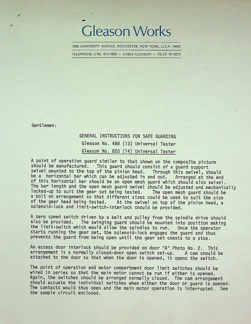
No. 488 & 820 Univ. Tester Safety Manual
Safety manual for Gleason No. 488 and No. 820 Universal Testers covering essential guarding design and operational safeguards. Provides comprehensive instructions on point-of-operation guard construction featuring a swivel support bracket, adjustable horizontal guard bar, and open mesh protective barrier. Details the solenoid-lock and limit-switch-interlock systems that prevent unsafe machine operation. Specifies access door interlock requirements and zero-speed switch operation with a 50 RPM threshold to halt machine movement before guard removal. Includes electrical safety circuit requirements and interconnected safety switch logic to ensure personnel protection during testing operations. Features complete electrical schematic drawing (TI3A Scale 488 Safety Package) illustrating the solenoid lock mechanism and coordinated safety switch network. Essential troubleshooting and maintenance guidance for technicians responsible for guarding system inspection and repair on these universal test machines.