JONES & LAMSON - Service Manuals
27 manuals available for download
JONES & LAMSON is a legendary manufacturer of precision machine tools, renowned for automatic lathes, turret lathes, and thread grinders built to exacting industrial standards. Our comprehensive documentation library includes original service manuals, repair guides, and detailed parts lists available for immediate PDF download, enabling technicians and operators to maintain, troubleshoot, and service their equipment with confidence. Whether you need an owner's manual for setup and operation or a workshop manual for in-depth maintenance procedures, our complete collection of technical documentation covers classic and automatic models across decades of production. Access authentic manufacturer resources designed to keep your JONES & LAMSON machinery running at peak performance.
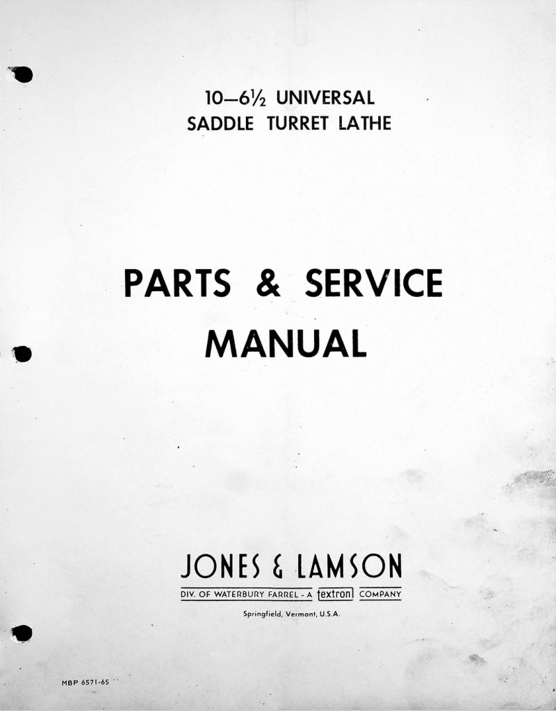
10-6.5 Universal Saddle Turret Lathe Service Manual
Service manual and parts reference for the Jones & Lamson 10-6½ Universal Saddle Type Turret Lathe. This comprehensive workshop manual covers installation procedures, operation fundamentals, and maintenance protocols for the machine and its hydraulic and electrical subsystems. The documentation provides guidance across mechanical, hydraulic, and electrical service areas, and notes that specific procedures and component specifications may vary depending on the accessories and optional equipment installed on your unit. Maintenance technicians should have working familiarity with the lathe's mechanical, hydraulic, and electrical systems to apply this manual effectively.
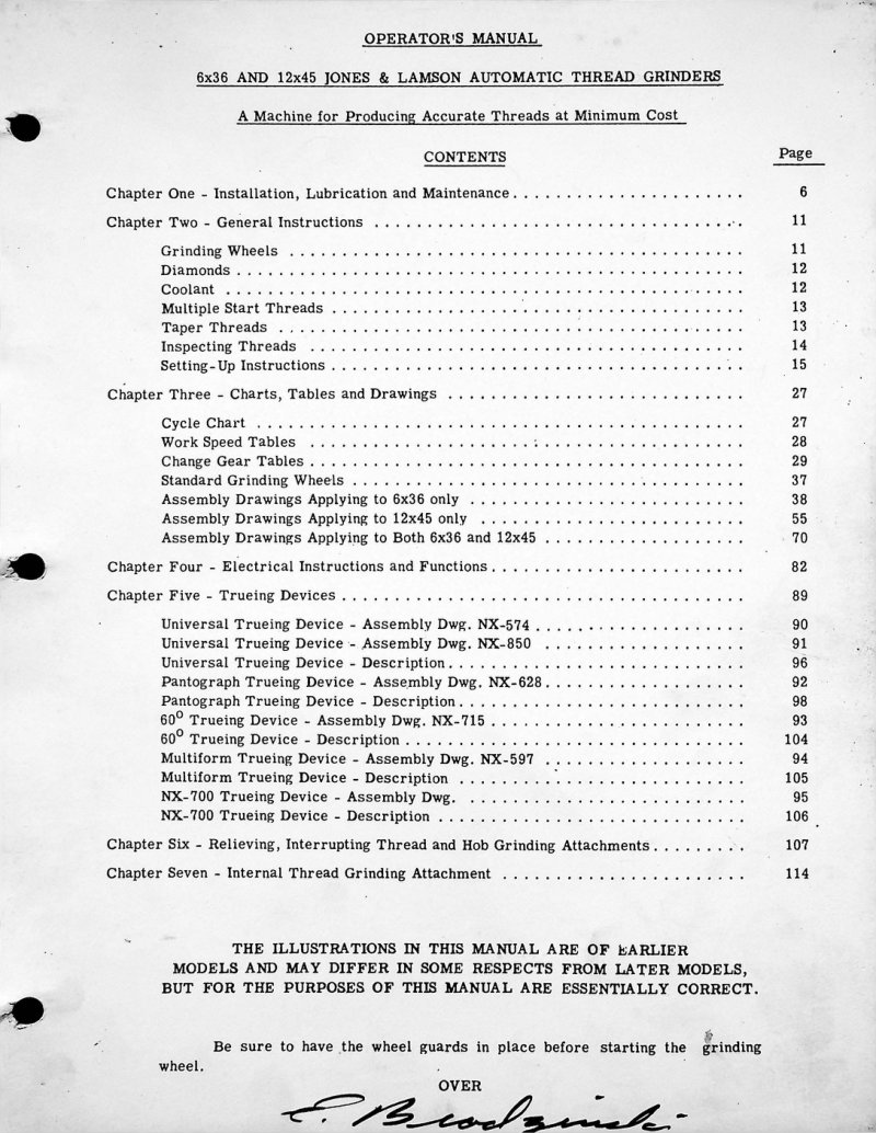
6x36 and 12x45 Thread Grinder Parts & Service
Comprehensive parts and service manual for Jones & Lamson Models 6x36 and 12x45 automatic thread grinding machines. This workshop manual covers installation procedures, lubrication schedules, and routine maintenance to keep both models running smoothly. Includes detailed operating guidelines, grinding wheel specifications and selection, coolant recommendations, and thread inspection methods to ensure precision work. The manual provides step-by-step setup instructions, cycle charts, work speed tables, and change gear tables tailored to each model's capabilities. Features assembly drawings for both models, electrical schematics and instructions, trueing device specifications, and specialized sections on relieving and interrupting thread attachments. Also contains internal thread grinding attachment details for expanded machining flexibility. An essential reference for operators and maintenance technicians working with these precision grinding systems. Table of Contents: - Chapter One - Installation, Lubrication and Maintenance - Chapter Two - General Instructions - Grinding Wheels - Diamonds - Coolant - Multiple Start Threads - Taper Threads - Inspecting Threads - Setting-Up Instructions - Chapter Three - Charts, Tables and Drawings - Cycle Chart - Work Speed Tables - Change Gear Tables - Standard Grinding Wheels - Assembly Drawings Applying to 6x36 only - Assembly Drawings Applying to 12x45 only - Assembly Drawings Applying to Both 6x36 and 12x45 - Chapter Four - Electrical Instructions and Functions - Chapter Five - Trueing Devices - Universal Trueing Device - Universal Trueing Device - Universal Trueing Device - Description - Pantograph Trueing Device - Pantograph Trueing Device - Description - 60° Trueing Device - 60° Trueing Device - Description - Multiform Trueing Device - Multiform Trueing Device - Description - NX-700 Trueing Device - NX-700 Trueing Device - Description - Chapter Six - Relieving, Interrupting Thread and Hob Grinding Attachments - Chapter Seven - Internal Thread Grinding Attachment
Automatic Turret Lathe - Service Manual
This comprehensive service manual for the Jones & Lamson Automatic Turret Lathe covers installation, operation, and maintenance. You'll find step-by-step guidance on shipment handling, unloading, cleaning, proper lifting and jacking, machine positioning, bar feed unit placement, and electrical connections. The lubrication section details coolant specifications, system checks, periodic maintenance schedules, and main drive motor lubrication. Leveling and alignment procedures address machine level readings, precision alignment techniques, and bar feed alignment to ensure optimal performance. Operation guidelines cover initial startup, daily checks, carriage and cross slide control, saddle controls, manual input methods, fast motion drop-out function, and proper use of end point and return stops. An essential reference for maintenance personnel responsible for assembly, troubleshooting, and preventive maintenance of this machine tool. Published by Waterbury Farrel Division of Textron Inc., Form No. TY-6217-R76, Copyright 1968. Table of Contents: - Introduction - General Specifications - Shipment - Unloading - Cleaning - Lifting Instructions - Sling Method - Jacking Method - Machine Location - Bar Feed Unit Location - Electrical Connections - Coolant - Lubrication - General - Lubrication Requirements - Initial Lubrication Check - Periodic Check Lists - Main Drive Motor Lubrication - Leveling and Alignment - Machine Level - Required Level Readings - Leveling Procedure - Precision Alignment - Aligning by Test Cuts from the Hexagon Turret - Bar Feed Alignment - Equipment Required - Level Requirements - Alignment With Machine Spindle - Initial Start-Up - Daily Start-Up - General Set-Up Procedures - Carriage and Cross Slide Controls - Positioning Carriage - Cross Slide Motion - Saddle Controls - Manual Input Controls - Fast Motion Drop-Out - End Point Stop - Return Stop
Fay Automatic Lathe Operating Instructions
Operating instructions for Jones & Lamson Fay automatic lathes, providing comprehensive technical guidance for machine setup, operation, and maintenance. Covers machine description and installation procedures, lubrication schedules and point locations, capacity specifications for various workpiece sizes, cam drum configuration and timing, carriage motion sequences and adjustments, back arm assembly procedures, feed change gear selection and meshing, and detailed setup instructions for dovetail slides, forming tools, relieving cams, and specialized tool blocks and attachments. Essential reference for operators and technicians working with these precision automatic turning machines.
Fay Automatic Lathe Operating Instructions
Operating instructions for the Jones & Lamson Fay automatic lathe, model Dept. 530. This workshop manual covers machine description, installation procedures, lubrication schedules, and comprehensive operating guidance for running the lathe safely and efficiently. The service manual includes detailed adjustment instructions for the carriage, back arm, cam drums, feed change gears, and optional attachments. Floor plans are provided for 8-inch through 24-inch Fay models, with in-depth sections explaining motions, speed settings, and calibration of critical components. Essential reference for operators and maintenance technicians working with this classic automatic lathe system. Table of Contents: - Adjustments: - Automatic Speed Change Clutches - Back Bar Bearings - Fast Motion Clutch - Front Former Slide Gib - Main Drive Clutch - Rear Former Slide Gib - Assemblies, General - Attachments: - Auxiliary Facing - Back Arm Turning - Bevel Facing - Center Drive - Overhead Slide - Taper Turning - Automatic Speed Change - Auxiliary Facing - Back Arm: - Dovetail Slide, Setting of - Feed Cam, Setting of - Former, Setting of - Motions of the Back Arm - Return Cam, Setting of - Setting of Backarm - Tools, Setting of - Tool Blocks, Setting of - Turning Attachment - Back Bar, Setting of - Cam Drums and Cams - Carriage Diagrams - Capacity - between Centers - Capacity - Swing - Carriage: - Double Control for - Dovetail Slide, Setting of - Former, Setting of - Locating the Carriage - Motions of the Carriage - Relieving Cam, Setting of - Relieving Device - Return cam, Setting of - Rock-in Cam, Setting of - Tools, Setting of - Tool Blocks, Setting of
Fay Automatic Lathe Parts & Service Manual
Comprehensive service manual for the Jones & Lamson Fay Automatic Lathe, covering setup, operation and daily maintenance routines for reliable long-term performance. Detailed adjustment procedures address automatic speed-change clutches, back bar bearings, fast motion clutch mechanics and main drive clutch operation. Back arm assembly sections explain dovetail slides, feed cams, formers, return cams and tool block positioning. Also covers carriage settings, cam drums and camming diagrams essential for precision work. Dedicated attachment sections cover auxiliary facing, back arm turning, bevel facing, center drive, overhead slide and taper turning operations. Includes assembly drawings and comprehensive parts lists for component identification and replacement. Workshop manual reference GL 198-R69. Table of Contents: - Adjustments: - Automatic Speed Change Clutches - Back Bar Bearings - Fast Motion Clutch - Front Former Slide Gib - Main Drive Clutch - Rear Former Slide Gib - Assemblies, General - Attachments: - Auxiliary Facing - Back Arm Turning - Bevel Facing - Center Drive - Overhead Slide - Taper Turning - Automatic Speed Change - Auxiliary Facing - Back Arm: - Dovetail Slide, Setting of - Feed Cam, Setting of - Former, Setting of - Motions of the Back Arm - Return Cam, Setting of - Setting of Backlash - Tools, Setting of - Tool Blocks, Setting of - Turning Attachment - Back Bar, Setting of - Cam Drums and Cams - Camming Diagrams - Capacity - between Centers - Capacity - Swing - Carriage: - Double Control for - Dovetail Slide, Setting of - Former, Setting of - Locating the Carriage - Motions of the Carriage - Relieving cam, Setting of - Relieving Device - Return cam, Setting of - Rock-in Cam, Setting of - Tools, Setting of - Tool Blocks, Setting of
Fay Automatic Lathes Parts List
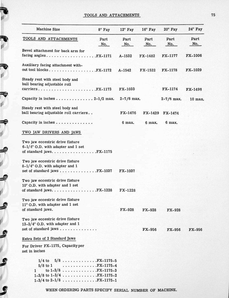
Comprehensive parts list for Fay automatic lathes covering 8, 12, 16, 20, and 24 inch swing models. This reference guide provides detailed part numbers and identification for tooling and accessories essential to these machines, including bevel and facing attachments, steady rests, two-jaw chucks and drivers, standard carriages, back arms, form tools, standard cams, and center drive units. An invaluable resource for technicians, operators, and maintenance staff sourcing replacement components or performing repairs on Fay automatics.
FAY Automatic Lathes Service Manual Vol. 2
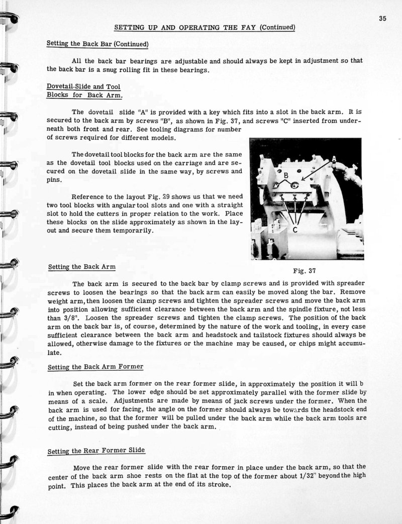
Volume 2 of the FAY automatic lathe service manual covers essential back bar setup and adjustment procedures critical to machine operation and precision. Pages 35–37 deliver detailed instructions for installing dovetail slides and tool blocks, positioning the back arm, and configuring feed cam settings for reliable performance. The manual includes step-by-step guidance on back arm feed cam setup, return cam adjustment, rear former slide roll carrier stop collar positioning, fast motion dog engagement, and back arm tool placement, supported by technical illustrations and mechanical diagrams that clarify cam profiles and component relationships. This section provides the technical foundation needed to maintain and troubleshoot FAY automatic lathe systems.
Hartness Double Spindle Flat Turret Lathe Parts (S/N 20809+)
Parts list for the Hartness Double Spindle Flat Turret Lathe, revised and corrected for machines manufactured after serial number 20809. This parts manual includes a detailed end elevation view with indexed part numbers keyed to feed mechanisms, gear boxes, spindle systems, and related assemblies. An essential reference for technicians performing maintenance, repair, or component replacement on this classic turret lathe.
Hartness Double Spindle Flat Turret Lathe Parts (S/N 50137+)
Parts list for the Hartness Double Spindle Flat Turret Lathe — a comprehensive numbered parts catalog with front elevation technical drawing identifying all major components and assemblies. This service documentation covers carriage feed systems, spindle mechanisms, turret assemblies, gear systems, and control levers essential for maintenance and repair. Applicable to machines with serial numbers 50,137 and above. Whether sourcing replacement parts or performing workshop service on this classic Jones & Lamson machine tool, this parts manual provides the technical reference needed for accurate component identification and ordering.
Hartness Flat Turret Lathe 3x36 Parts List
Comprehensive parts list for the Hartness Flat Turret Lathe 3x36, Gear Feed Type model. This document covers machines with serial numbers 11,000 and above. Includes numbered component references and precise part identifications needed for ordering replacement parts and performing maintenance on this classic industrial lathe. Use this list alongside your service manual and workshop documentation to source components correctly for repairs and routine upkeep.

Hartness Flat Turret Lathe Manual
Complete operational and maintenance manual for the Hartness flat turret lathe, published in 1915 by Jones & Lamson Machine Company. This 186-page workshop manual covers everything needed to operate, set up, and maintain this classic machine tool, including detailed procedures for tooling, workholding, speed and feed selection, and routine maintenance. An essential reference for machinists restoring or operating original Hartness equipment, with period-accurate technical guidance on lathe adjustment and troubleshooting specific to the flat turret design.
Hartness Flat Turret Lathe Parts List
Complete parts list and reference guide for the Hartness Flat Turret Lathe (3 x 36 x 15 inches), equipped with all-steel geared head. Provides numbered parts identification essential for ordering replacement components and performing maintenance on this classic production lathe. Includes front elevation schematic diagram to locate each part clearly. Applies to machines manufactured with serial numbers 30,000 and above. An invaluable resource for machine shop technicians, restoration specialists, and operators needing to identify or source components for repair and upkeep of this Jones & Lamson turret lathe model.
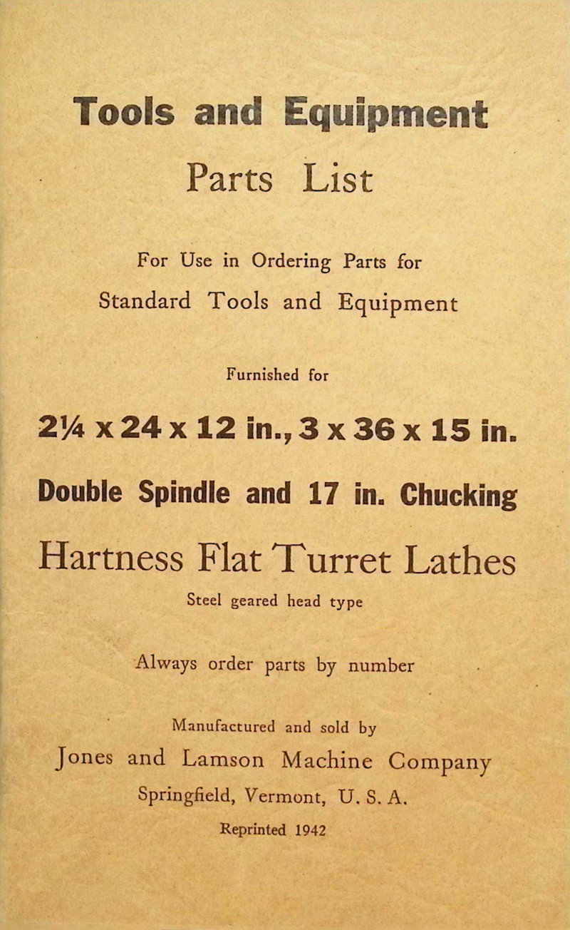
Hartness Flat Turret Lathes Parts List
Parts list for Hartness Flat Turret Lathes with steel geared head design. Covers double spindle models with 17 inch chucking capacity, available in 2.25 × 24 × 12 inch and 3 × 36 × 15 inch configurations. Original documentation from Jones & Lamson Machine Company, Springfield, Vermont. Includes numbered parts identification for tool plate bases, hexagon head bolts, tool holders, pipe assemblies, and associated fasteners. Essential reference for maintenance, repair, and parts ordering on these precision turret lathe systems.
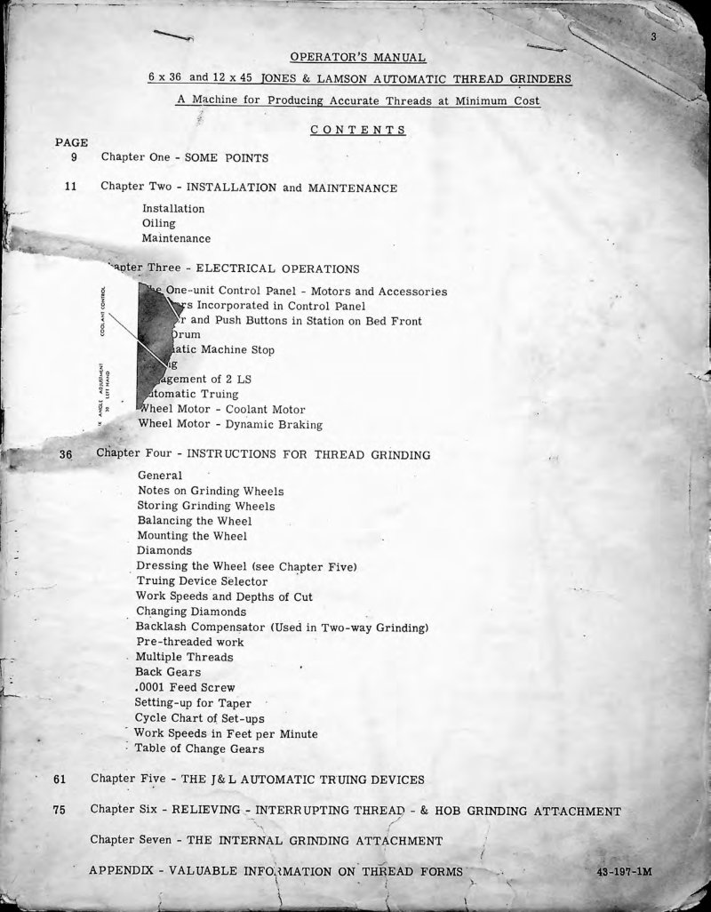
J&L Automatic Thread Grinders Operator's Manual
Operator's manual for Jones & Lamson 6x36, 12x45, and 5x30 automatic thread grinders. This comprehensive workshop manual covers installation setup, routine maintenance procedures, electrical operations, and detailed thread grinding instructions for all three models. Includes sections on automatic trueing devices, relieving and interrupting thread grinding attachments, hob grinding attachments, and internal grinding attachment configuration. Features a detailed front view diagram with all labeled components plus a thorough table of contents spanning 143 pages, making it an essential service reference for machine operators and maintenance technicians. Table of Contents: - Chapter One - SOME POINTS - Chapter Two - INSTALLATION and MAINTENANCE - Installation - Oiling - Maintenance - Chapter Three - ELECTRICAL OPERATIONS - One-unit Control Panel - Motors and Accessories - Motors Incorporated in Control Panel - Start and Push Buttons in Station on Bed Front - Drum - Automatic Machine Stop - Braking - Engagement of 2 LS - Automatic Truing - Wheel Motor - Coolant Motor - Wheel Motor - Dynamic Braking - Chapter Four - INSTRUCTIONS FOR THREAD GRINDING - General - Notes on Grinding Wheels - Storing Grinding Wheels - Balancing the Wheel - Mounting the Wheel - Diamonds - Dressing the Wheel - Truing Device Selector - Work Speeds and Depths of Cut - Changing Diamonds - Backlash Compensator (Used in Two-way Grinding) - Pre-threaded work - Multiple Threads - Back Gears - .0001 Feed Screw - Setting-up for Taper - Cycle Chart of Set-ups - Work Speeds in Feet per Minute - Table of Change Gears - Chapter Five - THE J&L AUTOMATIC TRUING DEVICES - Chapter Six - RELIEVING - INTERRUPTING THREAD - & HOB GRINDING ATTACHMENT - Chapter Seven - THE INTERNAL GRINDING ATTACHMENT - APPENDIX - VALUABLE INFORMATION ON THREAD FORMS
J&L Saddle Type Turret Lathe Service Manual
Service manual and parts list for Jones & Lamson Saddle Type Universal Turret Lathes. This workshop manual provides comprehensive installation instructions, machine leveling procedures, detailed lubrication specifications, and step-by-step adjustment guidance for clutch and brake systems. Covers daily operational protocols and preventive maintenance schedules essential for sustained machine performance. Includes detailed technical diagrams and schematics for machine setup, alignment, and routine servicing.
J&L Saddle Type Turret Lathes Instruction Manual
Instruction manual and parts list for Jones & Lamson Saddle Type Turret Lathes. This workshop manual covers installation and leveling procedures with detailed alignment diagrams for points A, B, C, and D using leveling screws, lubrication schedules with oil capacity specifications, motor wiring diagrams, clutch and brake adjustments, and complete operational instructions for safe machine operation and maintenance.
No. 5 Ram Type Turret Lathe Service Manual
Comprehensive workshop manual for the Jones & Lamson No. 5 Universal Ram Type Turret Lathe, covering setup, operation and maintenance essential for reliable machine performance. Provides detailed installation guidance, operational procedures and troubleshooting support for this heavy-duty precision lathe. Includes complete machine nomenclature, specifications and lubrication schedules to keep all mechanisms running smoothly. Step-by-step leveling and alignment instructions ensure proper machine geometry. Operation sections address operator pendant controls, headstock functionality and carriage and cross-slide mechanisms in practical detail. Throughout the manual, exploded assembly drawings with center lines, guide arrows and key reference letters show exact disassembly and reassembly sequences, making service and component replacement straightforward even for complex subassemblies. Table of Contents: - Machine Nomenclature - General Specifications - INSTALLATION SECTION - Shipment - Unloading - Cleaning - Lifting - Location - LUBRICATION SECTION - General Lubrication - Lubrication Specifications - Reservoir Capacities - Oil Reservoirs - Machine Lubrication Check List - Bar Feed Lubrication Check List - Main Drive Motor Lubrication - LEVELING AND ALIGNMENT SECTION - Machine Level - Precision Alignment - Bar Feed Level and Alignment - OPERATION SECTION - Operator Pendant - Start and Stop Buttons - Hydraulic Collet Chuck and Bar Feed - Headstock - Forward and Reverse Lever - Single Lever Dial Speed Selector - Manually Operated Collet Chuck and Bar Feed - Carriage and Cross Slide - Square Turret Lever - Carriage Handwheel
No. 7 Saddle Type Turret Lathe Service Manual
Comprehensive service and parts manual for the Jones & Lamson No. 7 Saddle Type Turret Lathe (A & B Series). This workshop manual covers installation, operation, and maintenance of this universal turret lathe, including detailed setup instructions for leveling and alignment. You'll find complete operational guidance for the operator pendant, headstock, carriage, cross slide, saddle, and all attachments, along with speed and feed charts tailored to different work. The manual details adjustments for every major component and provides thorough maintenance procedures, including spindle repair techniques and troubleshooting. A full parts list and ordering information help you source replacement components quickly. Published by Waterbury Farrel Division of Textron Inc. Table of Contents: - GENERAL SPECIFICATIONS - INSTALLATION - LUBRICATION - LEVELING AND ALIGNMENT - Machine - Bar Feed - OPERATION - Operators Pendant - Headstock - Carriage and Cross Slide - Saddle - Attachments - Speed and Feed Charts - ADJUSTMENTS - Carriage Side Gib - Carriage Hold Down Gib - Cross Slide Gib - Square Turret Clamp - Saddle Gib - Hexagon Turret Slide Gib - Hexagon Turret Clamp Ring - Carriage and Saddle Feed Lever - Carriage and Saddle Safety Clutch - Forward and Reverse Drive Clutch - Brake - Rapid Traverse Operating Lever - Belt Adjustment for Rapid Traverse Drive Unit - Oil Pump - Spindle Bearing - Carriage Taper Attachment - Carriage Thread Chasing Attachment - MAINTENANCE - To Remove Feed Rod from Aprons or Attachments - To Remove Carriage Feed Apron - To Remove Saddle Feed Apron - To Mount Feed Selector on Carriage and Saddle Feed Aprons - To Clean Square Turret Bearing and Time Locking Pin - To Remove Clutch Shaft - Spindle Repair - Spindle Pulling Equipment & "Go" - "No Go" Weights - HOW TO ORDER REPAIR PARTS
No. 9A Turret Lathe Parts List
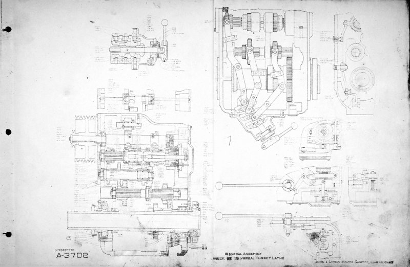
Parts list and technical drawings for the Jones & Lamson No. 9A turret lathe, an essential reference for maintenance, repair, and component identification. Includes general assembly drawings, detailed component views, cross-sections with part numbers, and exploded views of the turret head assembly and feed mechanisms. This workshop manual provides the technical documentation needed to source replacement parts, understand machine configuration, and support rebuild or restoration work on this precision machine tool.
PC-14 Optical Comparator Operating Manual
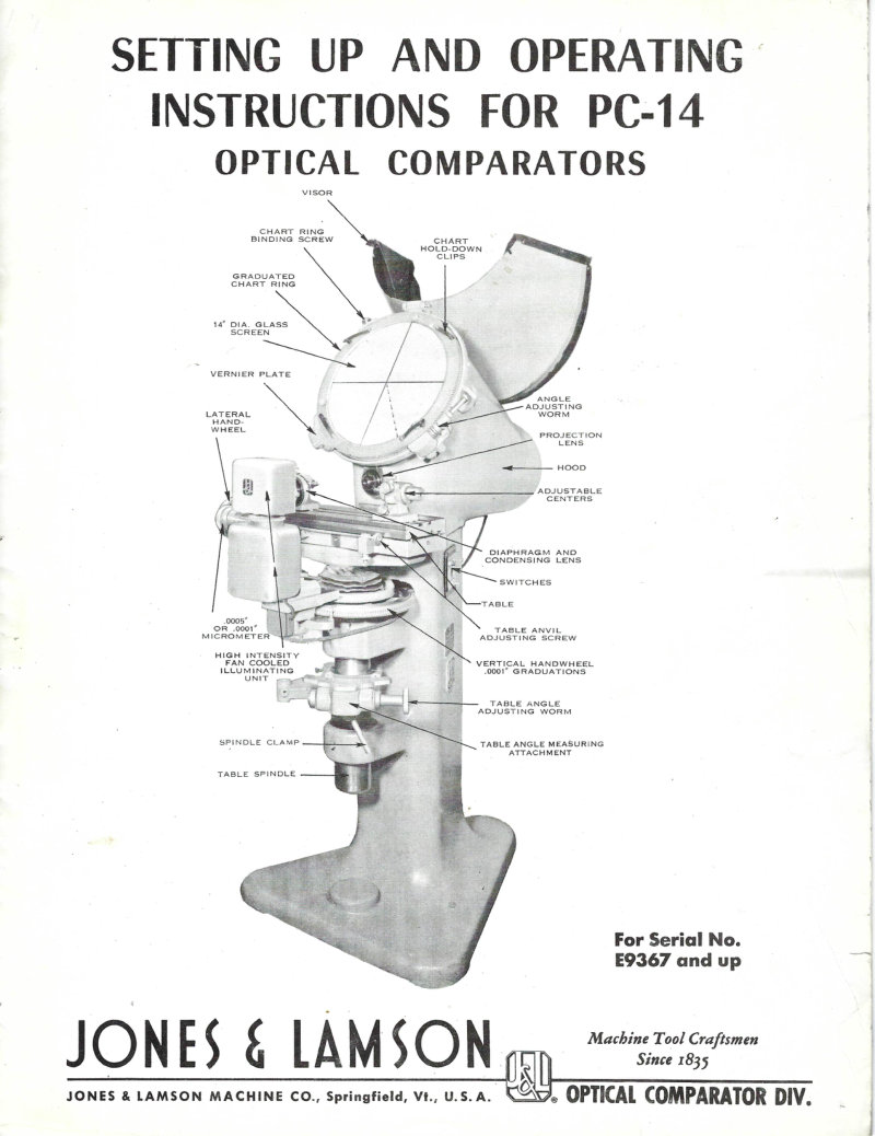
Operating and setup instructions for the Jones & Lamson PC-14 optical comparator (serial no. E9367 and up). This manual covers equipment operation, light beam adjustment, lens care, screen adjustment, magnification settings, table maintenance, mirror handling, and procedures for projecting flat objects and measuring angles, plus 20 best practice guidelines for optimal performance and reliable measurement results.
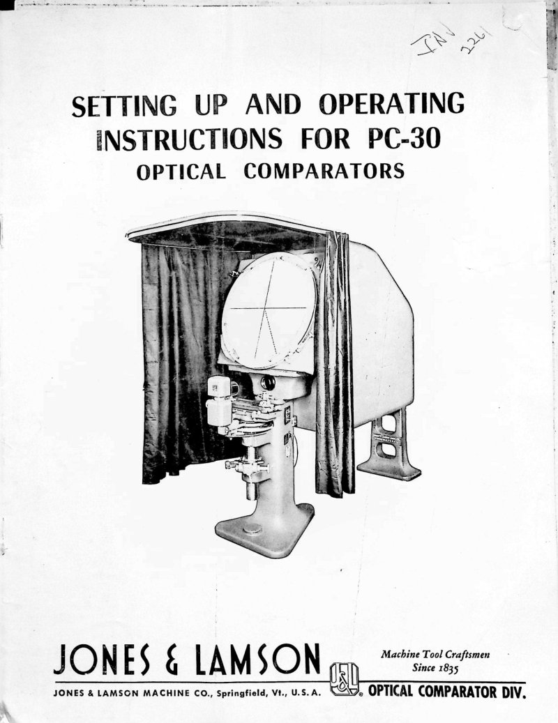
PC-30 Optical Comparator Operating Manual
Operating manual for the Jones & Lamson PC-30 optical comparator, covering complete setup and operation of this precision measurement instrument. Includes detailed instructions for table assembly with choice of 4 inch or 8 inch travel capacity, hood and chart ring assembly, light beam alignment and adjustment procedures, component installation and leveling techniques, and operational adjustments needed to achieve proper screen illumination. This workshop manual provides the guidance needed to configure and operate the PC-30 for accurate optical comparison work.
Ram Type Turret Lathe Instruction Manual
Instruction manual and parts list for Jones & Lamson Ram Type Universal Turret Lathes—an essential workshop reference for setup, operation, and routine maintenance of this precision machine tool. The manual covers proper installation and leveling using precision leveling screws, critical for achieving accurate spindle alignment. A detailed lubrication section includes an oil capacity table covering the headstock, carriage apron, saddle apron, and feed gear train, with oil grades specified for different spindle speed ranges. Practical guidance addresses clutch and brake adjustments, feed line pump settings, and bronze shoe lubrication. Troubleshooting and maintenance schedules help keep the machine running reliably between service intervals. The manual includes motor wiring diagrams, kerosene cleaning procedures, and illustrated sections with leveling diagram (Fig. 1), lubrication chart (Fig. 2), and clutch shaft accessibility reference (Fig. 3). A valuable resource for tool room managers, machinists, and maintenance technicians responsible for Jones & Lamson turret lathe operation and care.
Ram Type Turret Lathe Instructions Manual
Instruction manual and parts list for Jones & Lamson Ram Type Universal Turret Lathes, manufactured by Jones & Lamson Machine Co. in Springfield, Vermont. This workshop manual covers essential setup and operational procedures: installation and leveling, spindle lubrication with detailed oil capacity tables, cleaning protocols, and step-by-step adjustment instructions for clutch and brake assemblies. Includes a complete oiling diagram and mineral oil specifications matched to two spindle speed ranges (20–1000 RPM and 30–1500 RPM), ensuring proper machine performance across different production environments. Valuable reference for machinists, operators, and maintenance technicians working with Ram Type turret lathe equipment.
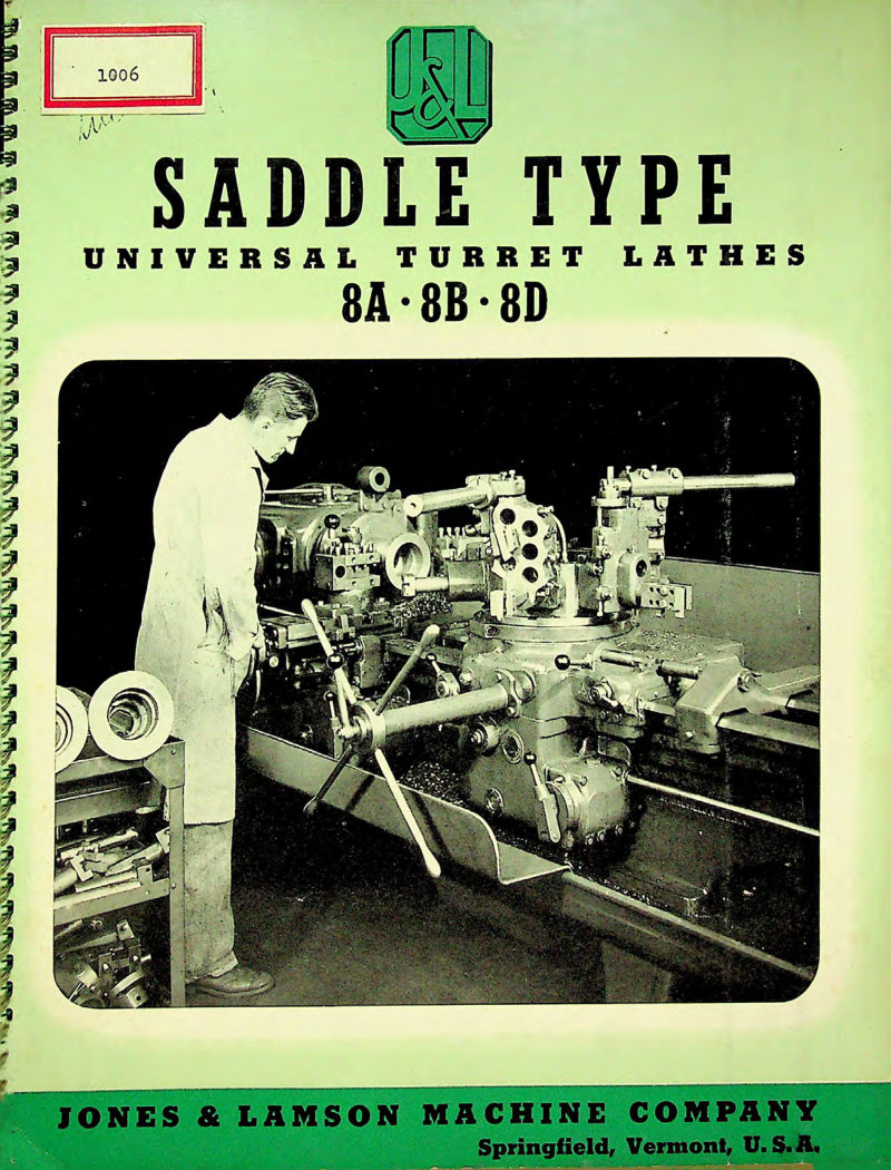
Saddle Type Universal Turret Lathes Technical Data
Technical data and specifications for Jones & Lamson Saddle Type Universal Turret Lathes, covering models 8A, 8B, and 8D. This service manual details the design, construction, and operational capabilities of these production lathes, including bridge-type carriage tooling configurations, broad spindle speed selection, hardened and ground steel ways for precision, turret indexing systems, integrated coolant delivery, and the Single Lever Control operating principle. The documentation addresses manufacturing efficiency, scrap reduction, and long-term machine reliability—essential reading for operators, maintenance technicians, and shop supervisors responsible for setup, troubleshooting, and upkeep of these industrial turning centers.
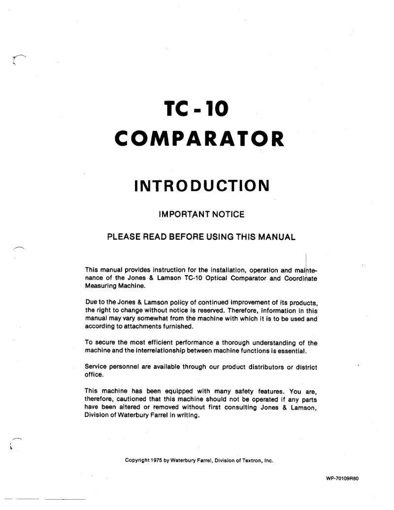
TC-10 Comparator Service Manual
Installation, operation and maintenance manual for the Jones & Lamson TC-10 optical comparator and coordinate measuring machine. This service manual covers nomenclature and specifications, floor plan layout, lubrication points and schedules, complete installation procedures, and operational techniques including lamphouse alignment, chart alignment, and reflection adjustment. Details measuring methods for vertical, horizontal, angular, progressive and decimetre applications. Maintenance section addresses routine care and troubleshooting. Includes exploded view drawings and comprehensive parts lists for the basic machine assembly, spindle assembly, fan, elevation handwheel, table assembly, power digital table, vertical encoder, lamphouse unit, and reflection attachments for both tungsten and novalite lamps. Essential workshop reference for setup, calibration and repair of this precision measuring instrument.
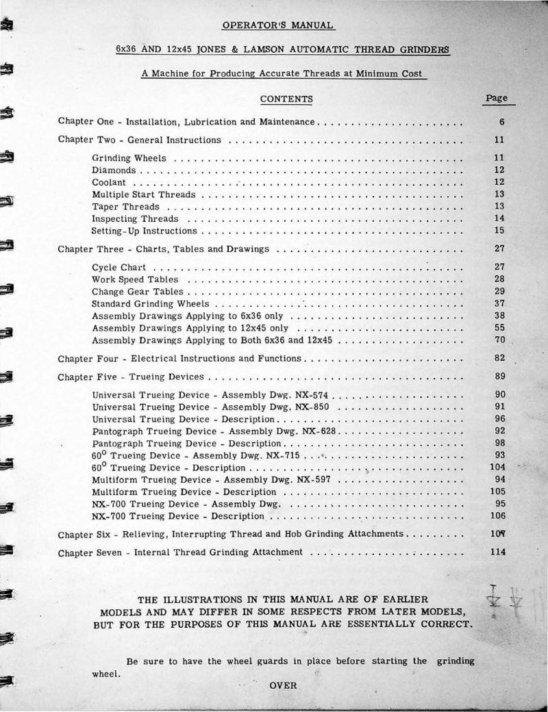
TG-6x36 and 12x45 Thread Grinder Operating Manual
Operating and maintenance manual for Jones & Lamson TG-6x36 and TG-12x45 automatic thread grinding machines. This comprehensive workshop manual covers everything required to install, set up, and operate these precision grinding systems: detailed lubrication schedules, routine maintenance procedures, and general operating principles. The guide includes extensive technical information on grinding wheel selection and dressing, diamond tool use, coolant management, and specialized grinding techniques for multiple-start threads and taper threads. Thread inspection methods and quality control procedures are explained alongside setup techniques, cycle charts, and work speed reference tables. Change gear tables help operators configure the machines for different thread pitches. The manual provides assembly drawings for standard grinding wheel components and complete electrical instructions for safe machine operation. Multiple trueing devices are covered in depth: universal, pantograph, 60-degree, multiform, and NX-700 models, with detailed instructions for each. Additional sections address relieving attachments, interrupting thread and hob grinding accessories, and internal thread grinding capability. Practical reference tables and cycle data make this an essential service manual for technicians and operators responsible for these machines. Table of Contents: - Chapter One - Installation, Lubrication and Maintenance - Chapter Two - General Instructions - Grinding Wheels - Diamonds - Coolant - Multiple Start Threads - Taper Threads - Inspecting Threads - Setting-Up Instructions - Chapter Three - Charts, Tables and Drawings - Cycle Chart - Work Speed Tables - Change Gear Tables - Standard Grinding Wheels - Assembly Drawings Applying to 6x36 only - Assembly Drawings Applying to 12x45 only - Assembly Drawings Applying to Both 6x36 and 12x45 - Chapter Four - Electrical Instructions and Functions - Chapter Five - Trueing Devices - Universal Trueing Device - Assembly Dwg. - Universal Trueing Device - Assembly Dwg. - Universal Trueing Device - Description - Pantograph Trueing Device - Assembly Dwg. - Pantograph Trueing Device - Description - 60⁰ Trueing Device - Assembly Dwg. - 60⁰ Trueing Device - Description - Multiform Trueing Device - Assembly Dwg. - Multiform Trueing Device - Description - NX-700 Trueing Device - Assembly Dwg. - NX-700 Trueing Device - Description - Chapter Six - Relieving, Interrupting Thread and Hob Grinding Attachments - Chapter Seven - Internal Thread Grinding Attachment