BOWENS - Service Manuals
2 manuals available for download
BOWENS is a trusted brand in professional photography lighting equipment, offering reliable solutions for studio and location work. Our comprehensive collection includes detailed service manuals, repair guides, and technical documentation available as PDF downloads to help you maintain and troubleshoot your equipment. Whether you need a workshop manual for routine maintenance, a parts list for component replacement, or a troubleshooting guide to resolve performance issues, you'll find professional-grade resources designed for both technicians and users. Access owner's manuals and maintenance documentation that cover the full scope of BOWENS lighting systems.
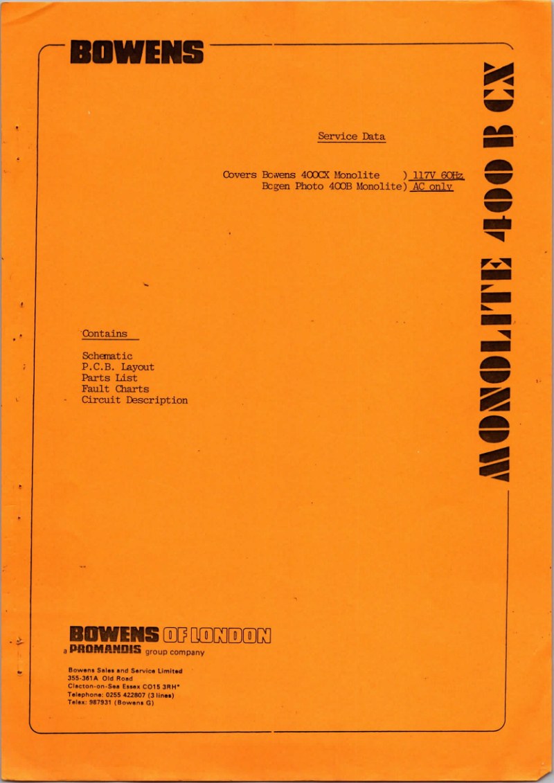
BOWENS - Bowens Monolite 400BCX Service Manual
Comprehensive service manual for the BOWENS Monolite 400B and Bcgen Photo 400B professional studio flash units. This workshop manual delivers detailed maintenance and repair procedures for these high-output studio lighting systems, covering the E.S. 275W modeling lamp, 117V 60Hz AC power input, 250W/s maximum power output, and 5600°K flash color temperature. Step-by-step disassembly instructions walk technicians through unit discharge, wrap removal, sub-assembly extraction, and component panel separation. Electrical configuration sections specify main input voltage, high-voltage output settings, flash intervals, and ready indicator adjustments. Troubleshooting flowcharts address common field issues such as flash ratio drift, modeling lamp flicker, and modeling lamp failure. The manual includes a complete electrical schematic diagram and full parts list identifying all resistors, capacitors, triacs, and trigger coils. Special attention is given to capacitor electrolyte leakage phenomena and engineering revisions implemented across the product generation. An essential reference for service technicians, repair professionals, and maintenance staff maintaining professional studio flash equipment. Table of Contents: - Schematic - P.C.B. Layout - Parts List - Fault Charts - Circuit Description

BOWENS - Bowens Prolite Service Manual
Comprehensive service manual for the Bowens Prolite professional flash generator series, covering models 41A, 41, 60, 82, 100 and 120. This workshop manual provides complete electrical and mechanical documentation for these professional studio lighting units. Detailed specifications and circuit descriptions cover the low voltage supply, charge circuits, regulation systems, glow-stop prevention and trigger/sync functions essential to flash operation. PCB layout diagrams are provided for both 117V and 240V versions, with alternative circuit board configurations (PCB2 through PCB5) specified for the higher-output models. The repair guide includes comprehensive electronic component identification—resistors, capacitors, diodes, integrated circuits, transistors and inductors—with component codes and precise board locations for accurate troubleshooting and replacement. Flash output and modelling light adjustment procedures are fully documented with clear technical guidance. General wiring diagrams and complete circuit schematics support diagnostic work and systematic repair. Structured troubleshooting flowcharts help technicians isolate faults efficiently. A detailed mechanical parts list covers chassis and reflector assemblies. An appendix documents design modifications across production versions, making this manual an essential reference for anyone servicing these professional flash units. PDF download includes all schematics, diagrams and parts data. Table of Contents: - Section 1. - Prolite 41A. - Section 2. - Prolite 41. - Section 3. - Prolite 60-82-100-120. - Section 4. - Modification Appendix. Mechanical Details.