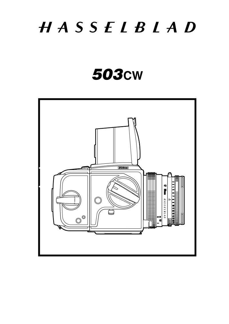
HASSELBLAD - Hasselblad 503CW Service Manual
 by HASSELBLAD
Comprehensive service manual for the Hasselblad 503CW camera body, a professional 6x6 format SLR system. This workshop manual provides detailed procedures for complete disassembly and reassembly of the camera mechanism, organized across 19 major sections with step-by-step instructions. The repair guide includes exploded views and assembly procedures for critical components: the winding crank assembly, left and right sidewalls with integrated electronics, front bayonet plate, auxiliary shutter and mirror assembly, mechanism plate, gear housing, and shell. A dedicated subsection addresses the front bayonet plate and auxiliary shutter assembly with mirror integration. The manual covers adjustment procedures, final assembly sequences, and flash meter calibration techniques. An extensive service revision history documents modifications across related models—the 501C, 503CX, 503CXi, 500C/M, and 501CM—enabling technicians to understand specific changes and improvements in each body variant. Specifications for specialized service tools required for proper maintenance and repair are included throughout.
Table of Contents:
- Camera body 503CW
- Reassembly
- October 1996
- Revision 0
- Front plate (30777)
- Fitting the front bayonet plate to the camera body
- Tension the drive spring by turning the outer gear wheel
- clockwise four turns. The front key will be positioned at
- the red index dot.
- A locking pin can be inserted through the inner cog
- wheel and the bracket to prevent the spring from
- unwinding.
- Install the winding knob V-2206 and tension the gear
- housing.
- Note! Make sure the aux-shutter is closed at this time.
- Fig.25.
- Install the front bayonet plate. Ensure that the push rod
- (22369) passes through the hole in the front plate and
- that the lens lock pin (13280) passes through the
- appropriate hole when the front plate is fitted and
- secured.
- Secure the two screws (823655) in the bottom plate
- and seal with loctite. Secure the four screws (820015)
- in the left and right hand walls, and the two screws
- (821017) in the focusing screen frame.
- Remove the temporary locking pin.
- Fig. 26.
- Intermediate gear (13112)
- Remove the screw (821631) and fit gear wheel (13112).
- Before meshing, align the gear (22699) with the rear
- plate and ensure that the adjustable pawl (13170) is in
- the middle cut out of ratchet wheel (20924).
- Hold the mirror actuating lever from the inside and
- secure the gear wheel (13112) with washer (810532)
- and screw(821631).
- Fig. 27.
- Fit the release bar (30375) and the spring (814512).
- Perform the necessary adjustment as described
- in section 5.
- Fig. 25
- Fig. 26
- Fig. 27
Documentation must be downloaded on a computer (PC, Mac, or Linux).
Do not use a smartphone or tablet to download documentation; they generally lack sufficient memory capacity to handle large files, and few users know how to locate the download folder on these devices.
Once downloaded, you can use it right away and even print the pages you need, or use your smartphone in photo mode to translate into the language of your choice: Google Translate
Document Details
- Format
- Pages
- 93
- Size
- 2.9 MB
- Category
- Photography