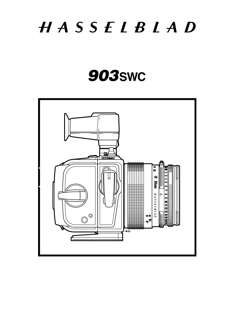
HASSELBLAD - Hasselblad 903SWC Service Manual
 by HASSELBLAD
Complete technical service manual for the Hasselblad 903SWC, a precision wide-format camera with permanently mounted Zeiss Biogon 38 mm lens and detachable optical viewfinder. This workshop manual provides authorized service technicians and specialized camera repair professionals with comprehensive maintenance and repair procedures. Opening sections establish general specifications covering film format compatibility (6x6 and 6x4.5 cm), focusing range, optical characteristics, and complete dimensional and weight reference data. A dedicated tools section catalogs all specialized equipment required for professional servicing—focusing gauges, shutter function test adapters, and precision optical group wrenches. The core of the manual delivers methodical step-by-step disassembly and reassembly protocols for the camera body, supported throughout by exploded views that clarify the camera shell, mechanism plate, and SWC viewfinder assembly, ensuring accurate component identification and correct reinstallation. Related service references are included. Revision 0, January 2001. An indispensable repair and maintenance reference for authorized Hasselblad service centers and technicians committed to restoring and preserving professional camera systems.
Table of Contents:
- 90306.eps
- January 2001
- 903swc
- Reassembly
- Revision 0
- 90309.eps
- Fig. 14
- Mount the housing (22323) on the camera
- body with the four screws (820015) and
- (820013). Check the axle so it turns freely.
- Put on the washer (810944) and the tooth
- wheel (22335).
- Place the inner part of the crank (A) in the
- housing and secure it with the nylon string
- Mount the crank (22321) with the two
- screws (823640) and the spring (22328)
- secured with the two screws 821662).
- Fig. 14
- Reassembling the lens and camera
- body
- Lubricate and then put the driving ring
- (21081-1) in the camera with its index mark
- aligned. Hold it in place by using two screws
- Fig. 15
- If a new driving ring (21081-1) is used, align
- the inner and outer driving rings according
- to fig. 16. Mark their relative position
- according to fig. 15.
- Place the gear (13320) and the ring (13322)
- on the lens and turn it clockwise to take up
- the play.
- Fig. 15
- Fit the camera body, with the driving ring
- aligned, on to the lens. Check that the gear
- and coggsector mesh properly and press
- down the body firmly.
- Tighten the two screws (820046) and check
- the function.
- Fig. 15
- Fig. 15
- Fig. 16
- "Mark"
- Driving ring alignment
- Axle
Documentation must be downloaded on a computer (PC, Mac, or Linux).
Do not use a smartphone or tablet to download documentation; they generally lack sufficient memory capacity to handle large files, and few users know how to locate the download folder on these devices.
Once downloaded, you can use it right away and even print the pages you need, or use your smartphone in photo mode to translate into the language of your choice: Google Translate
Document Details
- Format
- Pages
- 20
- Size
- 678.3 KB
- Category
- Photography