RICOH - Ricoh TLS401 Wiring Diagram
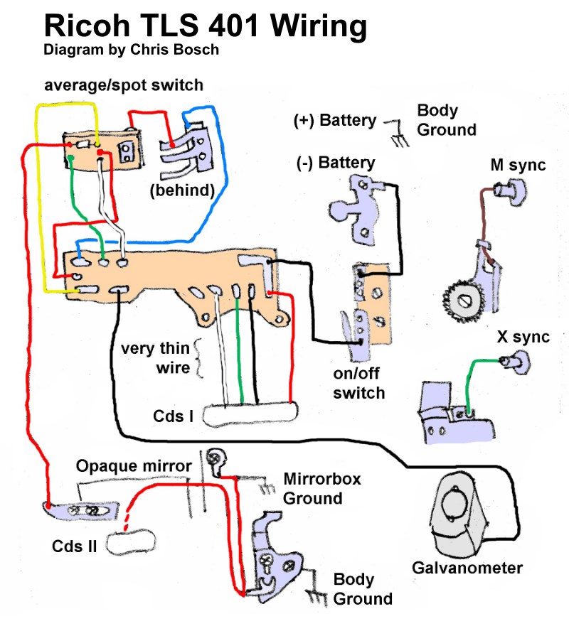
Comprehensive wiring diagram for the Ricoh TLS 401 SLR camera, presenting the complete electrical architecture in clear schematic form. This service manual maps all major electrical circuits and their interconnections: the average and spot metering selector switch, battery positive and negative terminals, power on/off switching, dual CdS light-sensitive cells (I and II), the reflex mirror assembly, M-sync and X-sync flash contacts, and the galvanometer that drives the exposure metering needle. Color-coded circuit paths make it straightforward to trace connections and isolate faults during repair or restoration work. The diagram includes grounding points to the camera body and mirror mechanism, component positioning within the housing, and the fine-gauge wiring runs characteristic of this model. Essential for technicians diagnosing electrical malfunctions, restoring vintage SLR systems, or understanding the metering and flash synchronization circuits of the TLS 401.
Documentation must be downloaded on a computer (PC, Mac, or Linux).
Do not use a smartphone or tablet to download documentation; they generally lack sufficient memory capacity to handle large files, and few users know how to locate the download folder on these devices.
Once downloaded, you can use it right away and even print the pages you need, or use your smartphone in photo mode to translate into the language of your choice: Google Translate
Document Details
- Format
- Pages
- 1
- Size
- 4.3 MB
- Category
- Photography