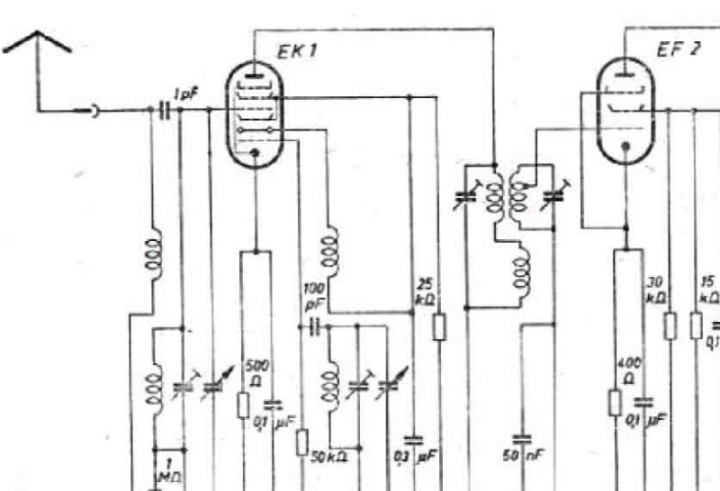
Telefunken T541 Autosuper Electronic Schematic
Electronic schematic diagram for the Telefunken T541 Autosuper radio receiver, presenting the complete circuit layout essential for understanding and servicing this classic tube-based radio. The schematic details the vacuum tube configuration (EK1, EF2, EB1, EF1, EL1), transformers, resistors, and capacitors throughout the signal path. Intermediate frequency is specified at 484 kHz. Includes tube socket identification diagram and power supply section showing 6V output. This technical drawing serves as the primary reference for repair, maintenance, and troubleshooting of the T541 Autosuper receiver. Suitable for technicians, radio restorers, and enthusiasts working on vintage tube radio restoration and service work.
Documentation must be downloaded on a computer (PC, Mac, or Linux).
Do not use a smartphone or tablet to download documentation; they generally lack sufficient memory capacity to handle large files, and few users know how to locate the download folder on these devices.
Once downloaded, you can use it right away and even print the pages you need, or use your smartphone in photo mode to translate into the language of your choice: Google Translate
Document Details
- Format
- Pages
- 1
- Size
- 96.1 KB
- Category
- Audio & HiFi