ELECTRONIQUE - Service Manuals
35 manuals available for download
ELECTRONIQUE specializes in comprehensive technical documentation for electronics enthusiasts and DIY professionals. Our extensive catalog includes detailed service manuals, repair guides, and troubleshooting resources covering radio, television, and general electronic devices. Whether you're seeking a workshop manual for circuit repair, a maintenance guide for battery systems, or step-by-step owner's manuals for electronics troubleshooting, our PDF downloads provide the technical knowledge needed to diagnose, repair, and maintain electronic equipment. From beginner learning materials to advanced repair techniques, ELECTRONIQUE offers practical, accessible documentation for every skill level.

100 Radio Faults: Troubleshooting Methods and Localization
Comprehensive troubleshooting manual for vintage radio receivers, covering 161 real diagnostic cases organized by functional symptoms. Published by Les Procédés Dorel, Paris, this service reference presents circuit-level repair methodology for output stages, intermediate frequency stages, oscillators, transformers, and capacitors. Each fault case includes diagnostic approach and schematic analysis for receivers operating across G.O./O.C./P.O. wavebands. The manual addresses receiver failure modes from complete audio loss through pickup function problems to radio reception faults, providing technicians with systematic localization methods and repair guidance grounded in practical workshop experience. Circuit schematics throughout support troubleshooting at the component level.

500 Faults: Radio, Television and Electronics
Fourth revised and corrected edition. Practical troubleshooting guide covering 509 common faults and their solutions across radio, television and electronic equipment. Presents systematic diagnostic methods and fault localization techniques for pinpointing electronic failures in audio, RF and power circuits. This repair manual addresses technicians and electronics engineers with step-by-step guidance on identifying faults and executing repairs, from silent receivers and audio distortion to sensitivity loss, oscillation problems and waveband issues. Spans audio frequency circuits, receiver pick-up and radio sections, transmitter stations, shortwave performance and high-frequency faults.
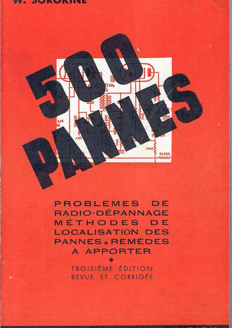
500 Radio Faults - Third Edition Revised
Comprehensive troubleshooting manual for radio receiver repair and fault diagnosis. Third revised edition. This service manual covers systematic fault localization across tube-based and AC-powered radio receivers, with detailed electrical schematics and practical voltage measurement techniques for both audio and RF circuits. Organized by symptom—from complete receiver silence through pickup and radio modes, to performance issues like hum, oscillation, distortion, and sensitivity loss—each section walks through component-level diagnosis and repair procedures. Includes dedicated sections on waveband-specific failures, shortwave performance problems, and frequency drift. Essential reference for technicians and hobbyists working with vintage radio equipment.
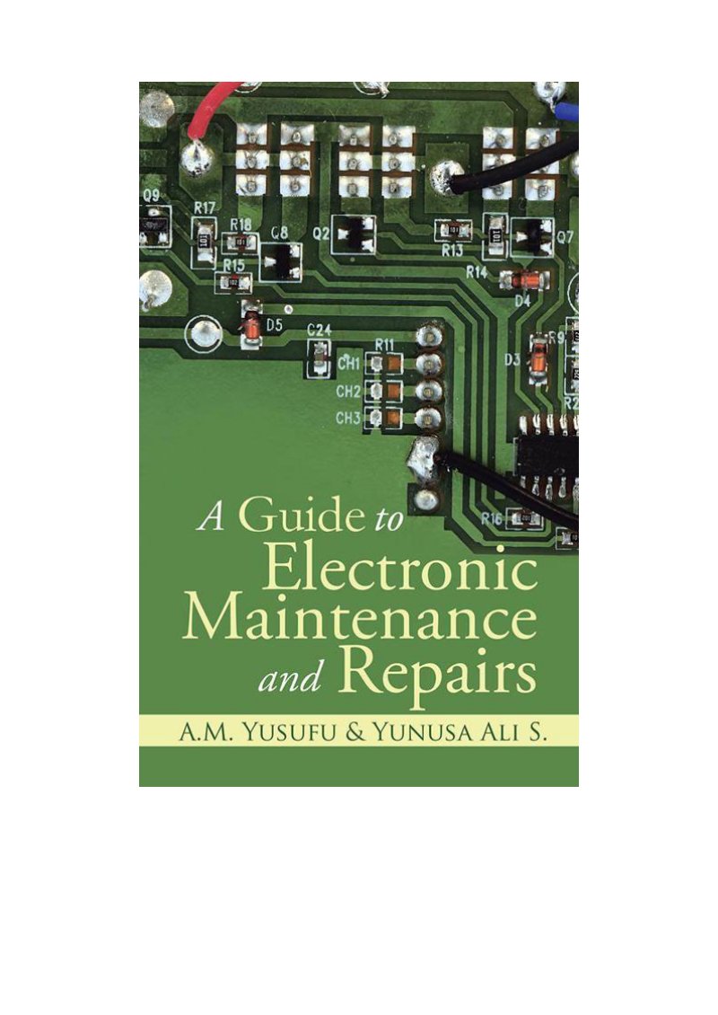
A Guide to Electronic Maintenance and Repairs
Comprehensive technical guide to electronic maintenance and repair, offering hands-on procedures for troubleshooting and servicing consumer electronics. Features detailed circuit board diagrams, component identification aids, and systematic repair workflows designed for technicians and experienced DIY enthusiasts. This workshop manual covers the fundamentals of diagnosing faults, replacing worn parts, and restoring equipment to working order. Whether you're performing routine maintenance or tackling a specific malfunction, the illustrated repair procedures and schematic references make this an essential service reference for electronics work.
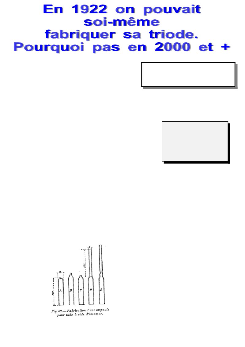
Construction of a Three-Electrode Vacuum Tube
Amateur radio manual providing comprehensive guidance on constructing a three-electrode vacuum tube, commonly known as an audion. The workshop manual covers the complete build sequence: bulb fabrication techniques, electrode assembly with tungsten filament preparation, grid winding procedures, and aluminum plate construction. Detailed instructions walk through the critical evacuation process using a mercury pump, the controlled heating procedures necessary for proper tube conditioning, and the final sealing method. Technical diagrams and assembly illustrations throughout make each step clear and reproducible. This construction guide serves as both a reference manual and practical workshop companion for anyone undertaking vacuum tube fabrication.
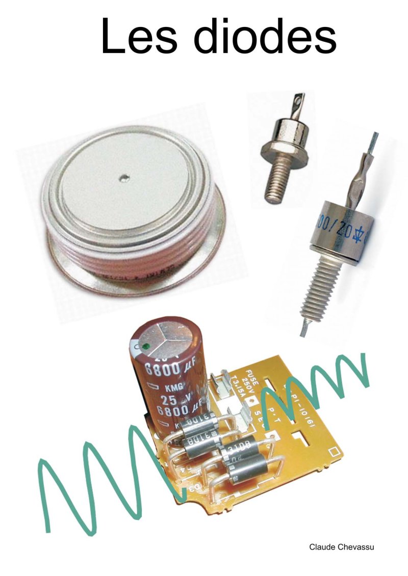
Diodes: Complete Technical Manual and Applications
Comprehensive technical manual on semiconductor diodes covering fundamental theory through advanced circuit applications. This 81-page repair and maintenance reference explains PN junction operation in detail, including equilibrium states and the mechanics of forward and reverse biasing. You'll find thorough electrical characteristics with mathematical equations and rigorous temperature effects analysis. The guide presents three increasingly practical diode modeling approaches, from ideal behavior to real-world models accounting for series resistance. Rectification applications receive extensive treatment: single and double alternance configurations, Graëtz bridge circuits, and complete filtering strategies for power supplies. Specialized diode types are covered comprehensively—Zener diodes for voltage regulation, fast recovery diodes for switching circuits, signal diodes, avalanche-controlled diodes, and LEDs. Each major section includes equivalent circuits, hydraulic analogies that build intuitive understanding, and worked design examples you can apply directly. You also get parameter datasheets, physical characteristics, circuit protection methods, diode schematic symbols, and numerous solved exercises. Whether you're troubleshooting a failing power supply, designing a precision rectifier, or studying semiconductor physics, this manual provides the technical depth needed for both educational mastery and practical field work.
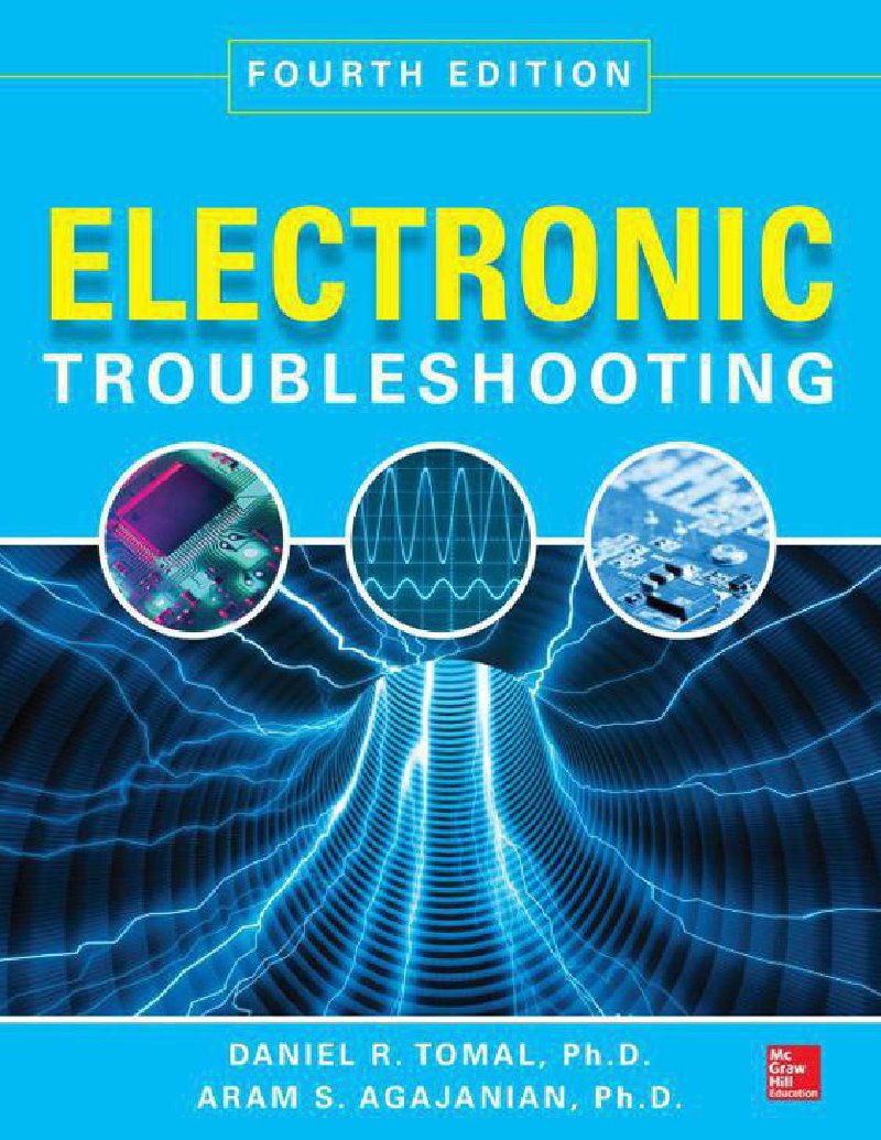
Electronic Troubleshooting, Fourth Edition
Fourth edition of Electronic Troubleshooting, a comprehensive guide to diagnosing and repairing electronic circuits and systems. This troubleshooting manual combines theory of operation with practical, real-world examples to help technicians isolate faults systematically. The coverage extends beyond basic circuit analysis to include modern computer networking and network devices, making it relevant for contemporary service work. Each chapter concludes with self-examinations and problem sets designed to reinforce troubleshooting methodology and validate your understanding. 483 pages of detailed technical content suitable for technicians, service professionals, and advanced hobbyists looking to strengthen their diagnostic skills.
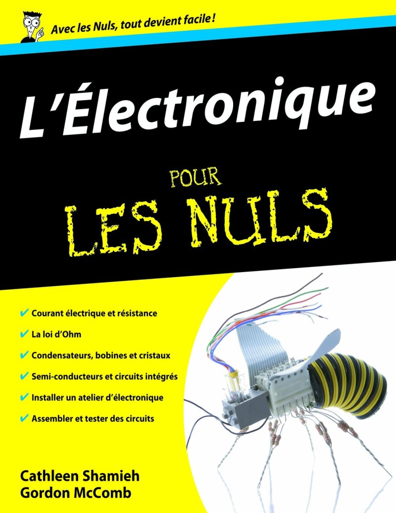
Electronics For Dummies - Complete Guide
A comprehensive guide to electronics fundamentals and practical applications covering electrical current, resistance, and Ohm's law through to semiconductors, transistors, and integrated circuits. This second edition walks readers through capacitors, inductors, and crystals with clear explanations suited to hands-on learners. The manual includes detailed sections on workshop setup and safety protocols, soldering techniques, and circuit assembly and testing methods. You'll find practical exercises throughout, guidance on component selection for different applications, and the foundation needed to understand how electronic devices actually work. Whether building your first functional circuit or troubleshooting component behavior, this guide provides the technical knowledge and step-by-step instruction beginners need to move confidently from theory to practice. Table of Contents: - Title Page .... page 1 - Copyright Page .... page 4 - Introduction .... page 15 - About This Book .... page 15 - Why Electronics? .... page 16 - Preconceived Ideas .... page 17 - Safety First .... page 18 - What You Will Find in This Book .... page 18 - First Part: The Basics of Electronics .... page 19 - Second Part: Getting Your Hands Dirty .... page 19 - Third Part: From Theory to Practice .... page 20 - Fourth Part: The Part of Tens .... page 20 - Icons Used in This Book .... page 20 - First Part - The Basics of Electronics .... page 6 - Chapter 1 - Electronics, What Is It and What Is It For? .... page 6 - Electronics, What Is It Exactly? .... page 6 - Electric Current, What Is It? .... page 6 - The Charge of Electrons .... page 6 - When Electrons Let Themselves Be Conducted .... page 6 - What Makes Electrons Run? .... page 6 - Exploiting Electrical Energy .... page 6 - Electrical Energy: It's All in the Movement .... page 6 - For Electrons to Reach Their Destination .... page 6 - It's Amazing What You Can Make Electrons Do! .... page 6 - Creating Good Vibrations .... page 6 - Seeing Is Believing .... page 6 - Sensing and Reacting .... page 6 - Controlling Movement .... page 6 - Solving Problems .... page 6 - Communicating .... page 6 - Chapter 2 - Manipulating Electric Current to Obtain a Particular Effect .... page 6 - How to Obtain Electrical Energy? .... page 6 - Direct Current Supplied by a Battery .... page 6 - Alternating Current Produced by a Power Plant .... page 6 - Transforming Light into Electricity .... page 7 - The Right and Wrong Direction: Real Electron Flow and Conventional Current Direction .... page 7 - Study of a Simple Circuit with a Light Bulb .... page 7 - Controlling Electric Current Using Basic Components .... page 7 - How to Control Current? .... page 7 - Active and Passive Components .... page 7 - Series and Parallel Connections .... page 7 - Series Connections .... page 7 - Parallel Connections .... page 7 - Combined Circuits .... page 7 - Creating Electronic Systems .... page 7 - A Sound in the Air .... page 7 - When Electrons Form Images .... page 7 - Chapter 3 - First Steps Toward Resistance .... page 7 - Resisting Current .... page 7 - Resistors: Passive but Powerful .... page 7 - What Are Resistors For? .... page 7 - Choosing a Fixed or Variable Resistor .... page 7 - Reading Fixed Resistor Specifications .... page 7 - Potentiometers .... page 7 - The Stated Power Is Not Indicated .... page 7 - Combining Resistors .... page 7 - Resistors in Series .... page 7 - Resistors in Parallel .... page 7 - Combining Series and Parallel Resistor Connections .... page 7 - Obeying Ohm's Law .... page 7 - Current Flowing Through a Resistor .... page 7 - It's Always Proportional! .... page 7 - One Law, Three Equations .... page 7 - Using Ohm's Law to Analyze Circuits .... page 7 - Calculating Current Intensity Through a Component .... page 7 - Calculating Voltage Across a Component .... page 7 - Calculating a Resistance .... page 7 - What Is Ohm's Law Really For? .... page 7 - Analyzing Complicated Circuits .... page 7 - Designing and Modifying Circuits .... page 7 - The Power of Joule's Law .... page 7 - Using Joule's Law to Choose Components .... page 7 - Joule and Ohm: The Ideal Pair .... page 7 - Circuits and Resistors, Practical Work .... page 7 - Chapter 4 - Capacitors Step by Step .... page 7 - Capacitors, Electrical Energy Reservoirs .... page 7 - Charging and Discharging Capacitors .... page 8 - Opposition to Voltage Variations .... page 8 - Alternating Current, An Alternative .... page 8 - What Are Capacitors For? .... page 8 - Capacitor Characteristics .... page 8 - What Charge Can a Capacitor Store? .... page 8 - Checking Maximum Working Voltage .... page 8 - Choosing the Right Type of Capacitor (Dielectric) .... page 8 - Size and Shape of Capacitors .... page 8 - Capacitor Polarity .... page 8 - Reading Capacitor Specifications .... page 8 - Variable Capacitance .... page 8 - Parallel Capacitor Assembly .... page 8 - Series Capacitor Assembly .... page 8 - What Is Capacitive Reactance? .... page 8 - Using Ohm's Law for Capacitive Reactance .... page 8 - Combining with Resistors .... page 8 - A Matter of Timing .... page 8 - Calculating Time Constants of an RC Circuit .... page 8 - Making a Timer .... page 8 - Selecting Frequencies with Simple RC Filters .... page 8 - The Low-Pass Filter .... page 8 - The High-Pass Filter .... page 8 - Cutting Frequencies Like Butter .... page 8 - Filtering Frequency Bands .... page 8 - Simple Capacitive Circuits, Practical Work .... page 8 - Chapter 5 - Coils and Crystals .... page 8 - Cousins That Embrace: Magnetism and Electricity .... page 8 - Magnets and Flux Lines .... page 8 - Producing a Magnetic Field with Electricity .... page 8 - Inducing a Current Using a Magnet .... page 8 - The Inductor, a Very Magnetic Coil .... page 8 - Measuring Inductance .... page 8 - Opposition to Current Variations .... page 8 - Alternating Current, or When the Alternative Becomes Paralyzing .... page 8 - Inductive Reactance, What Is It? .... page 8 - Applying Ohm's Law to Inductive Reactance .... page 8 - Everything Depends (Again) on Frequency .... page 8 - The Role of Inductors in Circuits .... page 8 - Isolating and Shielding Inductors .... page 8 - Reading Inductance Value .... page 8 - Combining Shielded Inductors .... page 8 - Filtering Signals with Inductors .... page 8 - Calculating RL Time Constant .... page 8 - And Now, Impedance! .... page 8 - Radio Broadcasting .... page 9 - Resonance and RLC Circuits .... page 9 - Crystals for Better Resonance .... page 9 - Following the Thread of Coils: Transformers .... page 9 - Interaction Between Unshielded Coils .... page 9 - Isolating Circuits from a Power Source .... page 9 - Raising or Lowering Voltage .... page 9 - Chapter 6 - The Vast World of Semiconductors .... page 9 - When Being a Conductor Becomes a Passing State .... page 9 - Doping Semiconductors .... page 9 - Creating Components by Combining N-Type and P-Type .... page 9 - A Junction Diode .... page 9 - Diodes and Polarization .... page 9 - When Current Passes Through the Diode .... page 9 - The Value of a Diode .... page 9 - Identifying Diodes .... page 9 - Which Way Does It Connect
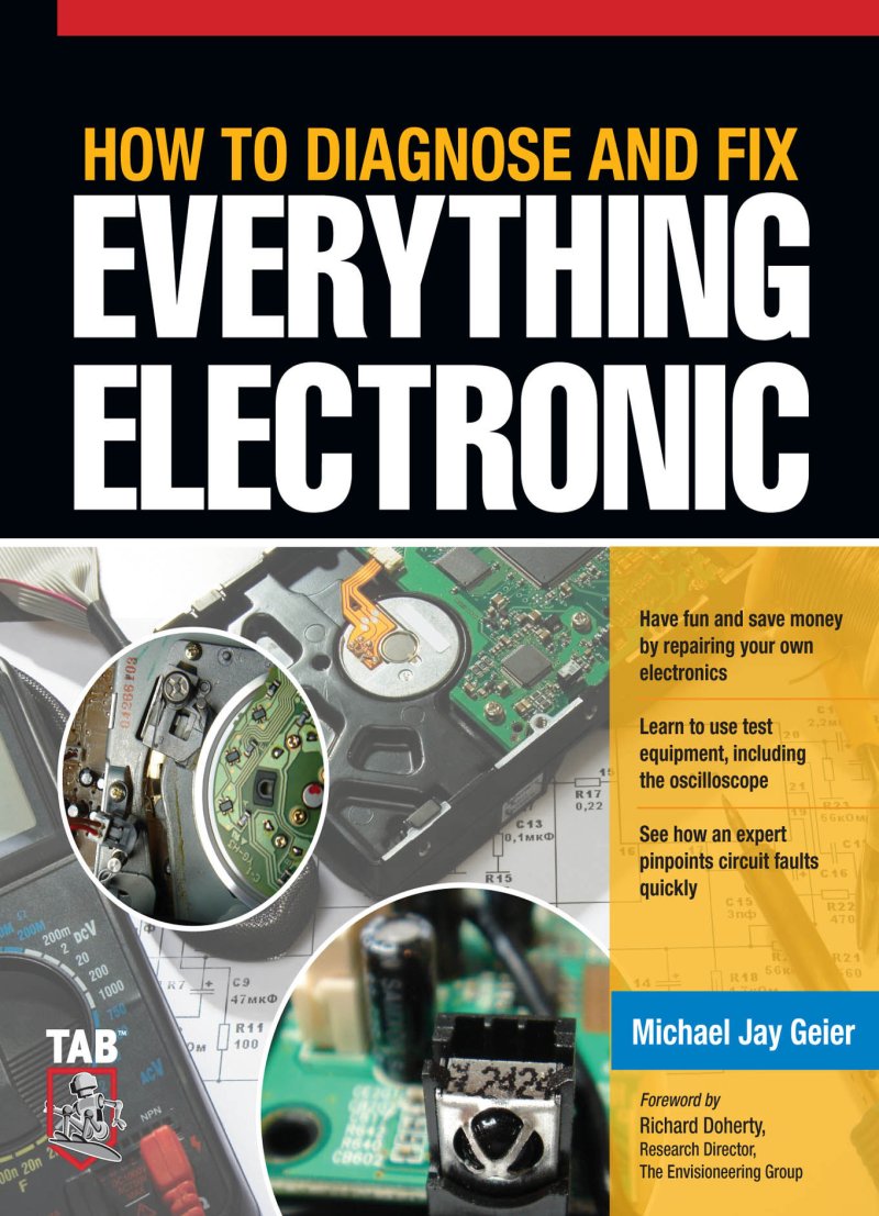
How to Diagnose and Fix Everything Electronic
Comprehensive troubleshooting and repair guide for electronic devices across multiple categories. Covers repair fundamentals, essential test equipment including oscilloscopes and meters, systematic circuit fault diagnosis methods, and proven practical repair techniques. This workshop manual provides the core knowledge needed to identify common electronic failures and execute effective fixes, making it invaluable for technicians, hobbyists, and anyone maintaining consumer electronics.
How to Troubleshoot & Repair Electronic Circuits
Comprehensive troubleshooting and repair manual for electronic circuits, originally published in April 1981 by TAB BOOKS Inc. This 380-page workshop guide provides systematic diagnostic procedures and hands-on repair techniques for identifying and correcting faults in circuit components and assemblies. The manual covers methodical approaches to circuit analysis, component testing, and practical repair strategies essential for technicians working with electronic equipment. An authoritative reference for understanding failure modes, measurement techniques, and restoration procedures across a wide range of electronic devices.
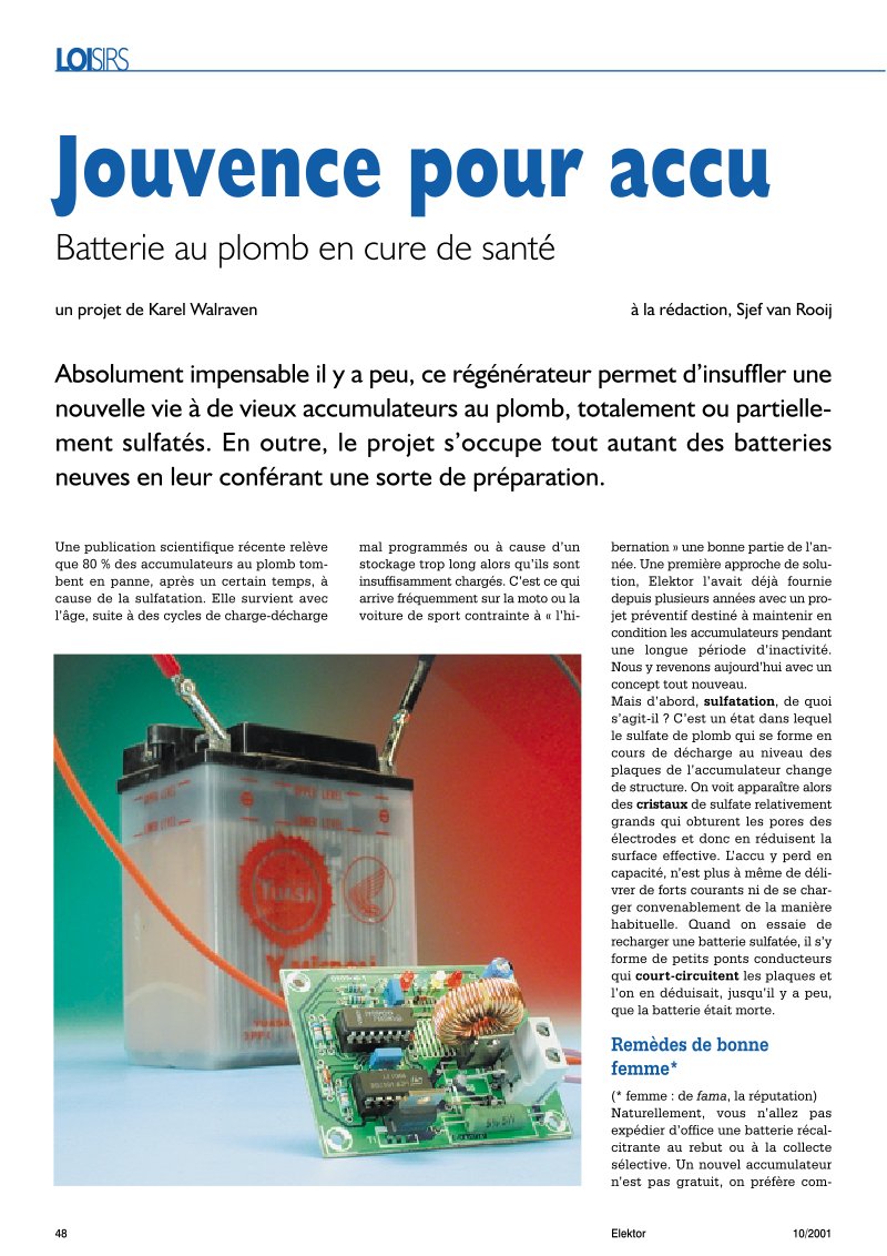
Lead Acid Battery Desulfator and Rejuvenator Circuit
This technical project presents a comprehensive service manual and repair guide for building a pulse-charge desulfator circuit specifically designed to revitalize sulfated lead-acid batteries. Sulfation is a common failure mechanism affecting approximately 80% of lead-acid accumulators in long-term storage or intermittent-use applications. The circuit implements proven pulse-charge technology to break down sulfate crystal deposits that accumulate on battery plates and restore effective electrode surface area. At its core, the design uses a 4047 astable oscillator generating 1 kHz square waves to control a power FET switching stage through an inductor network. This topology generates high-voltage discharge pulses ranging from 15V to 50V depending on the battery's internal resistance characteristics. Three operational amplifier comparators continuously monitor pulse amplitude and drive color-coded indicator LEDs that provide real-time battery health status: green for fully functional batteries, yellow for moderate sulfation, and red for severe degradation requiring extended treatment. The desulfator operates in three distinct modes: preventive maintenance for vehicles stored for extended periods, active desulfation for already-degraded batteries, or continuous operation paired with a trickle charger for long-term conditioning. Construction guidance covers essential topics including component selection criteria for reliability, PCB layout considerations to minimize EMI interference, proper grounding techniques, and detailed usage protocols for different battery conditions. The device successfully handles new battery conditioning, restoration of partially sulfated accumulators, and recovery of completely sulfated batteries that would otherwise be discarded.
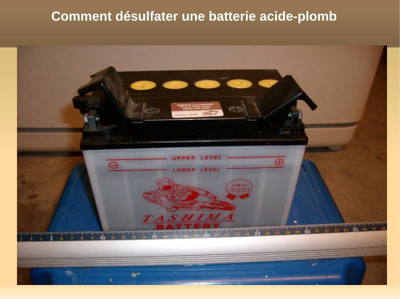
Lead-Acid Battery Desulfation Guide
Comprehensive technical guide for desulfating lead-acid batteries through controlled chemical treatment. This service manual delivers detailed step-by-step instructions for restoring sulfated batteries that have deteriorated after prolonged storage without maintenance charging, returning them to full operational capacity. The desulfation process covers draining spent electrolyte, thorough rinsing with demineralized water, dissolving magnesium sulfate into fresh electrolyte, and executing a regulated slow-charge cycle at precisely 1/10 of the battery's rated capacity. Specific safety requirements for sulfuric acid handling are thoroughly addressed, including mandatory protective gloves and eye protection protocols. Using a practical 30 AH battery example, the guide provides exact dosage calculations—approximately 1 gram of magnesium sulfate per amp-hour of capacity—ensuring proper chemical proportions for effective restoration. Complete charging requires 10 to 15 hours at the specified 3-ampere current, with clear monitoring procedures throughout the recovery process. An essential troubleshooting and maintenance reference for battery restoration, automotive preservation, and equipment upkeep where aging lead-acid batteries need revival.
Learning Electronics from Scratch - Level 2
This comprehensive educational manual is designed as a progressive continuation for learners who have completed foundational electronics knowledge. The second-level course builds upon basic concepts to introduce more complex electronic principles and practical applications. The material covers intermediate topics in circuit theory, component analysis, and hands-on electronic construction techniques. Through structured lessons and detailed explanations, students develop competencies in understanding multi-stage circuits, amplification systems, and advanced troubleshooting methods. The guide combines theoretical foundations with practical exercises that reinforce learning objectives and encourage experimentation. Readers will gain proficiency in reading schematics, identifying component functions, and understanding how different electronic elements interact within complete systems. This essential reference serves hobbyists, technicians in training, and anyone seeking to deepen their understanding of electronic principles beyond introductory level. Table of Contents: - Lesson 29-1: Level 2 - From an alternating voltage to a stabilized DC voltage - Rectifying an alternating voltage - What is the electrolytic capacitor for? - Reminder - The stabilized voltage - A zener diode as a stabilizer - Calculation examples - The disadvantages of the zener diode - A zener diode and a transistor - To increase the output by 0.7 volt - The value of resistor R1 - The voltage on the collector input - Lesson 29-2: Power supplies - Making the output voltage more stable - Designing a power supply - Calculation of the resistance - Calculation of resistor R2 - Calculation of resistor R4 - Calculation of resistor R3 - A power supply with Darlington amplifier - Calculation of resistor R1 - Calculation of resistor R2 - Calculation of resistor R4 - Calculation of resistor R3 - The values of resistors R4 and R3 - An operational amplifier as substitution for TR2 - Calculation of resistor R1 - Calculation of resistor R4 - Calculation of resistor R3 - The values of resistors R4 and R3 - The operational amplifier - Protection against short circuits - Lesson 29-3: LX.5029: Power supply 5V to 22V - 2A - The practical realization - Component list - Important - Lesson 30-1: Power supplies (continued) - Fixed voltage stabilizer integrated circuits - Table 1: Positive integrated regulators series 78xx - Table 2: Negative integrated regulators series 79xx - Table 3: Positive integrated regulators series 78Lxx - Table 4: Negative integrated regulators series 79Lxx - Input voltage - Output voltage tolerance - Input and output capacitor - To increase the output voltage - To increase the output current - Calculate the value of R1 - From theory to practice - Protection against short circuits - Lesson 30-2: Power supplies (continued) - Integrated circuits for variable voltages - Maximum input/output voltage - Minimum output voltage - Maximum output current - Maximum power - Fixed voltage power supplies with a variable regulator - Value of resistor R1 - Calculation of resistor R2 - The functions of diodes DS1 and DS2 - The value of electrolytic capacitors - To increase the output current - Calculate the value of R3 - Variable stabilized power supplies - The LM317 integrated circuit as a current stabilizer - Current as a function of R1 - Calculate the value of R1 - To obtain more current - Lesson 30-3: LX.5030: Dual power supply 5-9-12-15V at 1.2A - The practical realization - Calibration - Lesson 31-1: Operational amplifiers - The "+" and "-" input pins - Input with the "+" sign - Input with the "-" sign - Single power supply - Input with the "-" sign with a single power supply - The advantages of an operational amplifier - Gain - High input impedance - Low output impedance - Wide bandwidth - Component list for dual power supply LX.5030 - Lesson 31-2: Operational amplifiers (continued) - DC preamplifier, powered by dual voltage, using non-inverting input - DC preamplifier, powered by single voltage, using non-inverting input - DC preamplifier, powered by dual voltage, using inverting input - DC preamplifier, powered by single voltage, using inverting input - AC preamplifier, powered by dual voltage, using non-inverting input - AC preamplifier, powered by single voltage, using non-inverting input - AC preamplifier, powered by dual voltage, using inverting input - AC preamplifier, powered by single voltage, using inverting input - The advantages of a dual AC amplifier - Bandwidth - Gain limitation - Gain and bandwidth - Two operational amplifiers in series with non-inverting input - Two operational amplifiers in series with inverting input - To avoid auto-oscillations - Lesson 31-3: EN5031 and EN5032: Two BF signal generators - The triangular signal generator EN5031 - Component list EN5031 - Practical realization of the triangular signal generator - The sinusoidal signal generator EN5032 - Component list EN5032 - Practical realization of the sinusoidal signal generator - Lesson 31-4: EN5033: Capacimeter for multimeter - The operating principle - The first condition - The second condition - A good sketch is worth more... - Component list EN5033 - The electrical schematic - The practical realization - Capacimeter adjustment - To conclude - Lesson 32-1: Operational amplifiers: Commented schematic library (1) - Electrical schematics of op amp circuits - BF preamplifier using non-inverting input - BF preamplifier using inverting input - BF signal mixer - Differential amplifier - Voltage comparators - Window comparators - Window comparator variant - Schmitt trigger powered by dual voltage - Schmitt trigger powered by single voltage - Schmitt trigger with adjustable threshold - Lesson 32-2: Operational amplifiers: Commented schematic library (2) - Constant current generator powered by dual voltage - Constant current generator powered by single voltage - Sinusoidal wave generator powered by dual voltage - Sinusoidal wave generator powered by single voltage - Square wave generator powered by dual voltage - Square wave generator powered by single voltage - Calculate the frequency value - Triangular wave generator powered by single voltage - Sawtooth wave generator powered by dual voltage - Sawtooth wave generator powered by single voltage - Alternating signal rectifiers - Ideal rectifier powered by dual voltage - Ideal rectifier powered by single voltage - The electronics course and its formulas - About our way of writing formulas - Our formulas are correct! - Lesson 33-1: Operational amplifiers: Filters (1) - Low-pass, high-pass, band-pass and "notch" filters - Attenuation in dB per octave - What octave means - Low-pass filter - High-pass filter - Band-pass filter - "Notch" filter - First order band-pass filter - Example of frequency calculation - Example of capacitance calculation - Example of resistance calculation - First order high-pass filters - Example of frequency calculation - Example of capacitor capacitance calculation - Example of resistance calculation - Band-pass filters with an operational amplifier - Calculation example - Band-pass filters with two operational amplifiers - Calculation example - Very wide band-pass filters - Lesson 33-2: Operational amplifiers: Filters (2) - First order "notch" filters - Example of frequency calculation - Example of capacitance calculation - Example of resistance calculation - Second order filters - Second order low-pass filters - Second order high-pass filters - Second order "notch" filters - Higher order filters - Third order low-pass filters - Third order high-pass filters - Fourth order low-pass filter - Fourth order high-pass filter - To conclude - Lesson 34-1: What about dB (1) - Calculate dB when you know the voltage ratio - Calculate voltage gain when you only know the dB value - Calculate dB when you know the power ratio - Calculate power gain when you only know the dB value - Convert a voltage ratio to power and vice-versa - dB used as gain or as attenuation - Gain of a receiving antenna - Gain of a transmitting antenna - Lesson 34-2: What about dB (2) - Power gain of an HF transistor - Power gain of a Hi-Fi final stage - Calculation of attenuation of "crossover" filters for acoustic speakers - How to read the dB of a VU meter - Attenuation of television coaxial cables - Conclusion - Table of decibels from 0 dB to 35.0 dB - Table of decibels from 35.1 dB to 70.0 dB - Lesson 35-1:
Learning Electronics from Zero - Level 1
A comprehensive introductory guide to electronics fundamentals for complete beginners. This manual covers essential electrical concepts, circuit theory, and component behavior from the ground up. The Level 1 course progresses systematically through foundational topics—voltage, current, resistance, basic circuit analysis—building your understanding step by step. You'll develop the core knowledge needed before tackling advanced electronics. The structured approach and clear explanations make abstract concepts concrete and accessible, whether you're a student, hobbyist, or professional launching your electronics foundation.
Learning Electronics from Zero - Level 3 Course
Comprehensive Level 3 electronics course compiled from issues 55–79 of Electronique et Loisirs Magazine, serving as an advanced workshop manual for learners moving beyond foundational theory. This training guide spans 18 detailed lessons that combine theoretical foundations with hands-on circuit construction and practical troubleshooting applications. The curriculum covers superheterodyne receiver design and operation, transmitter conception and impedance matching techniques, numeric oscillators built with TTL and CMOS integrated circuits, amplifier classes (A, B, AB, C) and their distinct operating modes, flip-flop circuits for digital logic, both analog and digital frequency counters, binary and hexadecimal number systems for computational understanding, programmable unijunction transistors (PUT) and their circuit integration, and oscilloscope operation with multiple measurement methods and signal analysis techniques. Each lesson includes circuit diagrams, design principles, and practical construction guidelines suitable for hands-on experimentation. This course progresses steadily through intermediate to advanced topics, offering the technical depth needed to design, build, and troubleshoot real electronic circuits. Table of Contents: - LESSON No. 38-1 The principle of operation of superheterodyne receivers first part: the theory .... page 5 - Endodyne - Ultradyne - Tropodyne - Heterodyne .... page 5 - How a superheterodyne works .... page 5 - The oscillator of a superheterodyne .... page 5 - LESSON No. 38-2 second part: practical application Construction of a Medium Wave receiver .... page 5 - The practical realization .... page 5 - The adjustment .... page 5 - The reception of MW .... page 5 - LESSON No. 39-1 How to design a transmitter first part: the theory .... page 5 - What does impedance matching mean? .... page 5 - Connecting a collector to the base of an amplifier transistor .... page 5 - Adapting a final transistor to a normalized impedance of 50 or 75 ohms .... page 5 - The power amplifier transistor .... page 5 - The working frequency .... page 5 - The output power .... page 5 - The working voltage .... page 5 - The gain in dB .... page 5 - The ultimate advice .... page 5 - LESSON No. 39-2-1 How to design a transmitter part: .... page 5 - The electrical schematic .... page 5 - The low-pass filter calculation .... page 5 - The modulation stage .... page 5 - The practical realization of the transmitter .... page 5 - The practical realization of the modulator .... page 5 - The adjustment of the transmitter .... page 5 - LESSON No. 39-2-2 How to design a transmitter second part: practical application .... page 5 - The 50 or 75 ohm load probe .... page 5 - How to connect the modulator .... page 5 - The dipole transmitter .... page 5 - The assembly in the enclosure .... page 5 - LESSON No. 40-1 Digital oscillators first part: the theory .... page 5 - Digital oscillators with TTL and C/MOS integrated circuits .... page 5 - The oscillator with a triggered TTL inverter or "triggered inverter" .... page 5 - The oscillator with three non-triggered TTL inverters .... page 5 - The oscillator with two non-triggered TTL inverters .... page 5 - LESSON No. 40-1-2 Oscillators with a triggered C/MOS inverter .... page 5 - The oscillator with three non-triggered C/MOS inverters .... page 5 - The oscillator with two non-triggered C/MOS inverters .... page 5 - The oscillator with NE555 .... page 5 - Quartz oscillators with TTL-HC/MOS-C/MOS integrated circuits .... page 5 - TTL, HC/MOS and C/MOS integrated circuits .... page 5 - The oscillator with one HC/MOS inverter .... page 5 - The oscillator with HC/MOS type NAND .... page 5 - The oscillator with three TTL inverters .... page 5 - The oscillator with C/MOS inverter .... page 5 - The oscillator with C/MOS type NAND .... page 5 - The last advice .... page 5 - Quartz tolerance .... page 5 - Conclusion .... page 5 - LESSON No. 40-2 How to convert the 27 MHz band on medium waves? .... page 5 - Digital oscillators second part: practical application .... page 5 - Converting 27 MHz on medium waves .... page 5 - The electrical schematic .... page 5 - The practical realization .... page 5 - The connection to the receiver .... page 5 - LESSON No. 40-3 Construction of two timers with NE555 .... page 5 - Digital oscillators third part: practical application .... page 5 - The first timer .... page 5 - The calculation of duration in seconds .... page 5 - The calculation of frequency .... page 5 - The inverter S1 to C1-C2 .... page 5 - The inverter S1 to C3-C4 .... page 5 - The divider integrated circuit 4020 .... page 5 - Theoretical durations and real durations .... page 5 - The second timer .... page 5 - How to control maximum durations .... page 5 - The practical realization of the first timer .... page 5 - The practical realization of the second timer .... page 5 - The adjustments .... page 5 - Conclusion .... page 5 - The relay output contacts .... page 5 - LESSON No. 41-1 Class A, B or C amplifiers first part .... page 6 - Class A, B, AB and C amplifiers .... page 6 - Base polarization .... page 6 - Collector current .... page 6 - Transistor graph .... page 6 - A transistor in class A .... page 6 - LESSON No. 41-2 Class A, B or C amplifiers second part and end .... page 6 - A transistor in class B .... page 6 - A transistor in class AB .... page 6 - A transistor in class C .... page 6 - LESSON No. 42 The FLIP-FLOP .... page 6 - How a FLIP-FLOP circuit works .... page 6 - The SET-RESET type FLIP-FLOP with NAND .... page 6 - The SET-RESET type FLIP-FLOP with NOR .... page 6 - A pulse can replace the pushbutton .... page 6 - An ON/OFF type relay .... page 6 - An electronic switch .... page 6 - The D type FLIP-FLOP .... page 6 - The D FLIP-FLOP as frequency divider .... page 6 - An experimental assembly for Set-Reset FLIP-FLOP .... page 6 - The electrical schematic and practical realization .... page 6 - LESSON No. 43-1 An analog frequency meter for analog or digital multimeter .... page 6 - Electrical schematic .... page 6 - Practical realization .... page 6 - Assembly in the enclosure .... page 6 - Which tester (multimeter) to use? .... page 6 - Adjustments .... page 6 - Input sensitivity .... page 6 - LESSON No. 43-2-1 Practical application A 5-digit 10 MHz digital frequency meter .... page 6 - Practical application .... page 6 - AC voltage and frequency .... page 6 - The time base stage .... page 6 - The input stage .... page 6 - LCD counter-decoder stage .... page 6 - LESSON No. 43-2-2 The Latch and Reset signals .... page 6 - Power supply stage .... page 6 - Practical realization .... page 6 - Assembly in the enclosure .... page 6 - Adjustable capacitor C16 adjustment .... page 6 - How to build this assembly? .... page 6 - LESSON No. 44 CD40103 .... page 6 - The 8-bit CD40103 counter .... page 6 - The meaning of indications on the pins .... page 6 - A comprehension test .... page 6 - Conclusion .... page 6 - Build this assembly .... page 6 - LESSON No. 45 Binary and hexadecimal numbers .... page 6 - Decimal numbering .... page 6 - Binary numbering .... page 6 - Hexadecimal numbering .... page 6 - Decimal to hexadecimal conversion .... page 6 - Hexadecimal to decimal conversion .... page 6 - Decimal to binary conversion .... page 6 - Binary to decimal conversion .... page 6 - Another method to convert binaries to hexadecimals and vice versa .... page 6 - If you
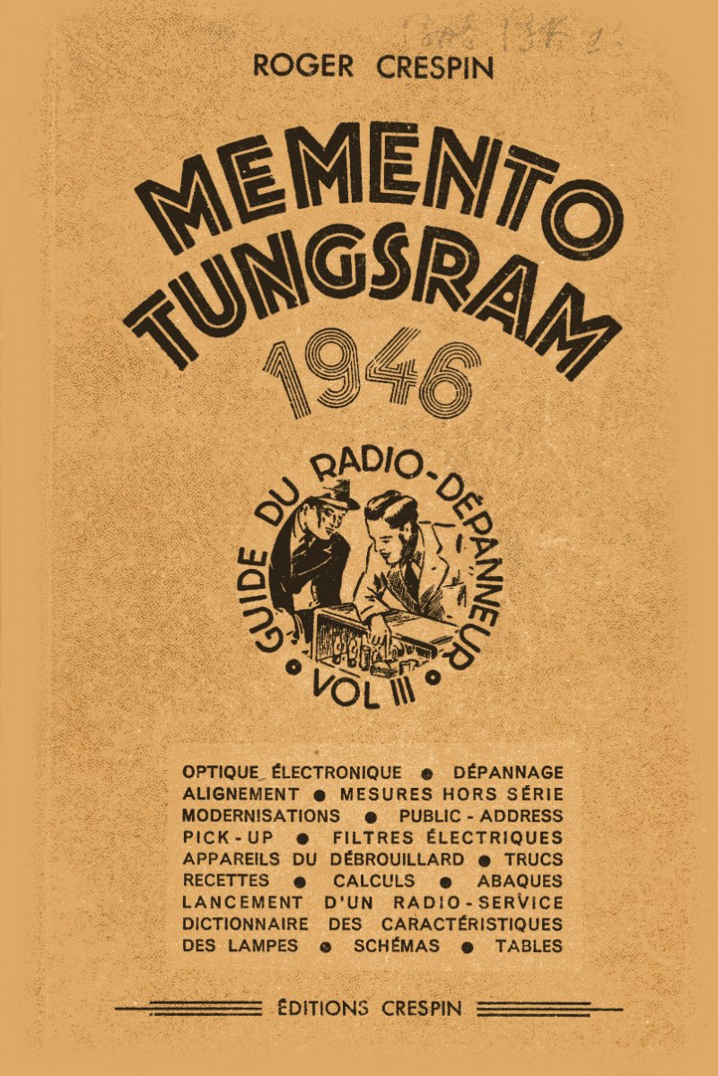
Memento Tungsram Volume 3 - Radio Service Guide 1946
Memento Tungsram Volume 3 is a comprehensive radio service manual from 1946 for technicians servicing tube-based receivers and audio equipment. This technical reference covers the essential foundations of mid-century radio repair, beginning with electron tube theory and cathode ray tube operation before moving into practical diagnostic and alignment procedures. The guide addresses the core challenges radio technicians faced: tracking down hum interference, eliminating parasitic oscillations, diagnosing distortion and signal loss, and executing precision receiver alignment on both direct amplification and superheterodyne designs. A substantial section details transformer and coil design principles, winding tables for custom construction, booster circuits, and speaker transformer specifications. The manual includes practical guidance on building and calibrating essential workshop instruments—modulated heterodyne oscillators, audio oscillators, wattmeters, and ohmmeters—along with sections on magnetic and crystal pick-up systems, wireless reproduction equipment, and electrical filter design. Technical tables throughout provide standard resistor and capacitor values, lamp characteristic data, and calculation aids for rapid on-the-job reference. An invaluable period document for anyone restoring vintage radios or studying the diagnostic methods that defined professional radio repair practice.
New Rational Radio Troubleshooting Technique
Fourth edition manual covering rational troubleshooting techniques for radio receivers using vacuum tubes and transistors. Includes fundamental concepts, voltage divider circuits, and practical guidelines for radio repair technicians.
One Hundred Problems for Radio Technical Agents
Collection of 100 problems and exercises for radio technicians. Content covers circuit studies including resonant circuits, coupled circuits, antennas, and thermionic tubes. Each problem includes questions and solution guidance. Based on textbooks on radioelectricity theory and practice, and electronic tube applications.
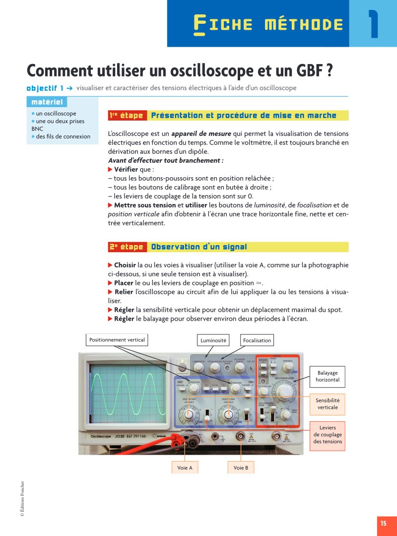
Oscilloscope and Function Generator Operating Guide
Operating guide for oscilloscopes and function generators, with comprehensive coverage of the Hameg HM303-6 oscilloscope. This manual walks you through all essential measurement principles and setup procedures for both educational laboratory work and professional electronic testing. You'll find detailed instructions on power-on procedures, horizontal sweep operation, vertical sensitivity calibration, and zero-point adjustment for accurate readings. The guide covers continuous voltage measurement techniques, sinusoidal signal generation and analysis, frequency measurement using the f=1/T relationship, and amplitude determination across a range of signal types. Practical step-by-step procedures explain how to visualize electrical tension as a function of time, measure peak-to-peak voltages, and configure the function generator for specific frequency and amplitude outputs. Also included are automatic measurement functions, safety guidelines, and complete technical specifications. This is an invaluable reference for technicians and students working with test equipment in electronics labs and field applications.

Pannes Radio: Tubes and Transistor Receivers
Seventh edition of this field-tested troubleshooting guide covers 344 documented fault cases in tube and transistor AM/FM radio receivers. Organized as practical case studies drawn directly from service experience, this manual walks you through systematic diagnosis and repair of receivers using both tube and solid-state circuits. The first section focuses on tube receiver faults—silent receivers, poor performance with hum, oscillation, motor-boating, power loss, and distortion, along with reception issues such as lack of sensitivity, hum on stations, and poor shortwave performance. The second section addresses transistor receiver troubleshooting, measurement techniques specific to solid-state circuits, fault location strategies, diode and transistor testing procedures, and amplifier gain verification. The final section covers alignment procedures for both AM and FM receivers. This is essential reference material for anyone maintaining or repairing vintage radio equipment in the field or workshop.
Practical Guide for the TSF Radio Repairman
Practical guide by Alain Boursin for radio technicians and repairers. Covers essential instruments and troubleshooting methods: voltmeter construction and theory, test socket, ohmmeter description and construction, use of ohmmeter, AB-4 Sector schematics, short-circuit and break detection, voltage measurements, intensity measurements, wavemeter utility and construction, resistance measurement abacus, circuit alignment, sector noise, various panels, and hand tricks.
Radio Receiver Alignment - Circuits and Coils
Technical manual on radio receiver alignment covering oscillating circuits, coil winding (bobbinages), single control systems, and troubleshooting anomalies. Includes practical alignment methods, self-inductance coefficients, dimensional specifications for coils with variable winding configurations, and characteristic data. Second edition revised and expanded.
Radio Receiver Improvement and Modernization
Technical guide on retrofitting and upgrading vintage radio receivers. This workshop manual details practical methods for modernizing older sets to restore and enhance sensitivity, selectivity, output power, and audio fidelity. Covers the historical development of receiver design from the 1920s onward, with in-depth sections on circuit improvements, battery supply conversions and alternatives, fading compensation systems, audio filtering techniques, automatic gain control implementation, and antenna noise rejection. Essential reference for anyone restoring or servicing classic radio equipment.
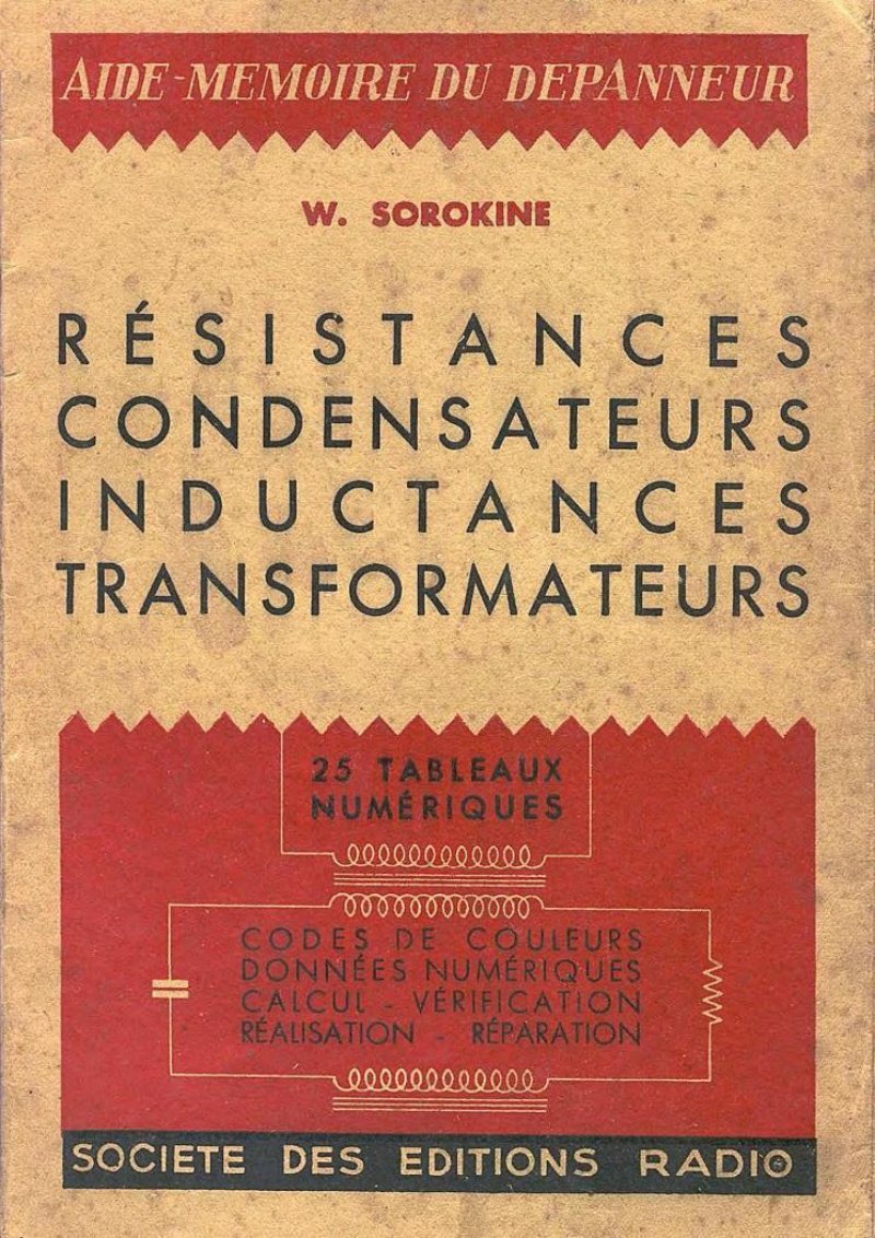
Radio Technician's Reference - Components Guide
Radio Technician's Reference - Components Guide is an essential workshop resource for anyone servicing and troubleshooting radio equipment. This comprehensive parts and repair manual provides practical reference data for the core passive components found in every radio circuit: resistors, capacitors, inductors, and transformers. The guide opens with a thorough breakdown of resistor color coding systems for quick component identification on the bench, then walks through wattage calculations, precision grades, and how to combine resistors in series and parallel configurations to achieve exact impedance values. A dedicated section covers capacitor marking and color codes, with clear guidance on series and parallel combinations for circuit modification and repair. The power supply section addresses transformer faults, systematic testing procedures, and the design calculations needed for rewinding or replacement. Inductance coils receive detailed treatment covering construction principles and practical winding tables that let technicians verify or rebuild coils to specification. The audio output transformer section explains their role in matching impedance between output stages and speakers, shows how to select replacements, and provides construction reference tables. Throughout the manual, 25 numerical tables deliver color codes, reference data, calculations, and step-by-step verification methods—exactly what a technician needs without flipping through multiple sources. This troubleshooting guide and components reference has proven invaluable in the field for maintenance, repair diagnosis, and component replacement work on vintage and active radio repair jobs.

Radio Troubleshooting for Everyone
Guide for amateurs and artisans on TSF (radio) receiver troubleshooting and methodical adjustment. Covers control apparatus for measuring electrical parameters, test equipment schematics, and practical procedures for diagnosing and repairing radio receivers. Includes detailed diagrams of measuring instruments and test circuits.
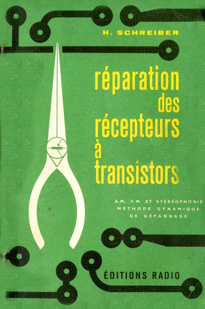
Repair of Transistor Receivers
Technical manual by H. Schreiber for repairing AM, FM and stereophonic transistor receivers. Covers transistor operation principles, practical troubleshooting methodology, circuit stages analysis, and repair techniques. Includes dynamic fault detection method. Third edition published by Éditions Radio. Table of contents: 1. The transistor: operation, characteristics, amplification stage, biasing (p. 8) 2. The transistor receiver: HF, IF, detection, and audio amplifier stages (p. 50) 3. Technician's equipment: universal meter, electronic voltmeter, generators, accessories (p. 76) 4. Practical troubleshooting: signal tracer, faulty stage location, repair techniques (p. 138)
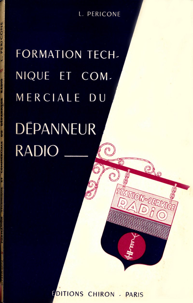
Technical and Commercial Training for Radio Technicians
Training manual for radio technicians covering technical troubleshooting and commercial operation. First part addresses technical diagnosis methods for radio receivers, including measurement apparatus such as universal controller, heterodyne oscillator, and lamp tester. Second part covers commercial aspects and client management for radio repair services.

The Art of TSF Radio Receiver Troubleshooting and Tuning
Technical manual by Lucien Chrétien on troubleshooting and adjustment of radio receiver sets (TSF). Covers diagnostic methods, circuit analysis, component identification, and practical repair procedures. Includes discussion of electromagnetic phenomena related to radio receivers.
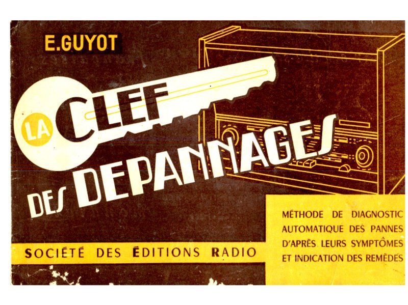
The Key to Troubleshooting - 5th Edition
Automatic diagnostic method for radio receiver failures. Organized by symptom with corresponding diagnoses and remedies. Covers lamp issues, receiver malfunctions, circuit problems, and transformer defects. Technical troubleshooting guide for radio technicians and users.
Troubleshooting Analog Circuits
Comprehensive troubleshooting guide for analog circuits, offering practical diagnostic methods and real-world repair strategies. Published by National Semiconductor as part of the EDN Series for Design Engineers, this 234-page technical manual provides engineers and technicians with systematic approaches to identifying and resolving analog circuit faults. Covers measurement techniques, signal tracing, component testing, and fault isolation procedures essential for service and maintenance work. An invaluable workshop reference for circuit repairs, diagnostics, and performance verification.

Troubleshooting and Adjustment of Transistor Radio Receivers
Technical manual by Fernand Huré covering troubleshooting and calibration procedures for transistor radio receivers. Includes chapters on receiver components, measurement instruments, safety precautions during repairs, general fault diagnosis methods, and adjustment procedures for AM/FM superheterodyne receivers. Contains practical guidance on testing transistors, circuit analysis, signal tracing, and alignment techniques. Features reference tables for common faults organized by circuit stage. 4th edition published by Librairie Parisienne de la Radio. Table of contents: - Chapter I: Components of a transistor superheterodyne receiver (p. 13) - Chapter II: Required test instruments — transistor testers and meters (p. 17) - Chapter III: Precautions during transistor radio troubleshooting (p. 89) - Chapter IV: General fault-finding methods and receiver alignment procedures (p. 99) - Chapter V: Measurements and alignment of AM and FM superheterodyne receivers (p. 150)
Troubleshooting Basics Vol. 1: Power and Audio
Practical radio troubleshooting course covering the fundamentals of AC power supply design and low-frequency audio amplification. Volume 1 walks through transformer winding identification, rectifier valve characteristics, measurement techniques, and systematic troubleshooting methods essential for servicing vintage radio receivers. Includes complete schematics, block diagrams, and technical reference tables for component specifications and performance curves. A foundational workshop manual for understanding power supply failures, audio distortion, and valve-related faults in tube radio equipment. Table of Contents: - Bases of Interference (Volume II: Detection, HF, MF, frequency change) - Alignment of Radio Receivers - Radio Technician's Aide-Memoire - Troubleshooting of Brand Name Receivers (obsolete) - Agreement Blocks (obsolete) - Radio Panels - TV Panels - Radios with Battery and Mixed Power Supply - Depanning of TV Panels by Wire - Radio Formulary - Schematic (Annual Collection)
Troubleshooting Basics Vol. 2: HF, MF, Detection
Technical manual covering HF and MF signal detection and demodulation. Discusses detector circuits using diodes and vacuum tubes, filter design, frequency change techniques, and practical repair procedures for radio receivers. Includes oscilloscope waveforms, circuit diagrams, and theoretical explanations for technicians. Second revised and expanded edition by W. Sorokine published by Société des Éditions Radio.
Troubleshooting Manual for Radio Receivers
Practical troubleshooting guide for radio receivers. Contains chapters on preventive maintenance, first symptoms of failures, and testing apparatus including simple continuity testers and universal controllers. Includes circuit diagrams and test setups using milliameter, ohmmeter, and voltmeter configurations.

Troubleshooting TSF Radio Receivers by Image
French technical manual for troubleshooting and repairing TSF (radio) receivers through visual diagnosis and frequency adjustment. Includes color code for resistances, tool specifications, schematic symbols, and procedures for silent faults and symptomatic failures. Contains alignment and specific assembly instructions for high-end radio sets.