BULLARD - Service Manuals
34 manuals available for download
BULLARD machine tools have been engineered for precision manufacturing across vertical turret lathes, boring mills, and drilling equipment. Our comprehensive catalog provides service manuals, repair guides, and detailed parts lists in PDF format to support maintenance, troubleshooting, and workshop operations. Whether you need a user manual for equipment setup, a maintenance guide for preventive care, or technical documentation for replacement parts identification, BULLARD documentation delivers the specifications required for reliable machine performance and extended equipment life.
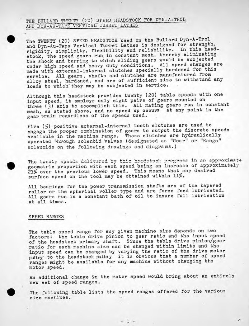
20 Speed Headstock Service Manual
Service manual for the Bullard 20 Speed Headstock with Hydraulic Power Pak, issued in March 1973 (Document No. D-DT-3-73). This workshop manual provides detailed technical guidance for servicing and maintaining the hydraulic-drive headstock assembly. Includes rear-view photography of the power pak with covers removed, exposing the electrical components, control boxes, and complete hydraulic system layout for inspection and repair procedures.
24-Inch Vertical Turret Lathe Parts List
Complete parts list for the Bullard 24-inch Vertical Turret Lathe, an essential reference for technicians maintaining or restoring this industrial machine tool. Covers erecting components including bed, reservoir cover, spindle assembly, and eye bolt specifications. The oil tank unit 16 breakdown details the tank itself, oil guards, tank cover, and all associated fasteners required for proper installation and sealing. Cleanout plate unit 17 documentation includes hand hole cover, pipe cap, and nipple components. Each entry provides precise part numbers, dimensions, and hardware specifications for accurate identification and ordering of replacement parts.
36-Inch Vertical Turret Lathe Parts List
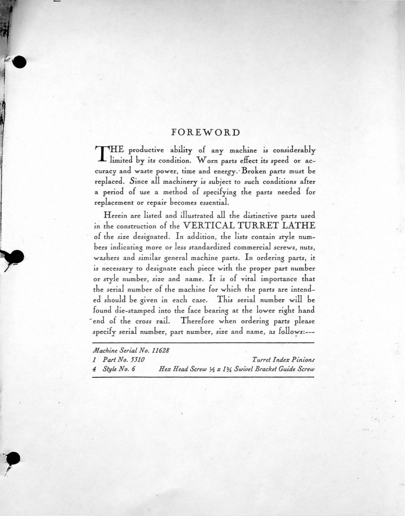
Parts list for the Bullard 36-Inch Vertical Turret Lathe, serial number 17788. This comprehensive parts manual documents component specifications across multiple divisions, with particular detail on bed assembly construction. Includes part numbers, style designations, dimensions, and nomenclature for all major and fastening components. Coverage spans bed parts such as water guard, table spindle, eye bolts, thrust washers, dust caps, bushings, counterweight rod, felt retainer, thrust nuts, wipers, and associated hardware. Also catalogs standardized commercial fasteners—screws, nuts, washers—and general machine parts with full specifications. An essential reference for identifying replacement parts, ordering components, and understanding the lathe's structural assembly. Table of Contents: - # FOREWORD - Machine Serial No. 11628 - 1 Part No. 5810 Turret Index Pinions - 4 Style No. 6 Hex Head Screw ⅜ x 1¾ Swivel Bracket Guide Screw
36-Inch Vertical Turret Lathe Parts List
Comprehensive parts list for the Bullard 36-inch vertical turret lathe, essential for identifying and ordering genuine replacement components. The document emphasizes best practices when requesting parts—specifying the machine serial number, part number, size, and component name ensures you receive the correct items for your specific unit. Details the distinctive machine components alongside cross-references to standardized commercial fasteners, screws, nuts, washers, and general machine hardware with their corresponding style numbers. Includes critical reference information for locating the serial number, which is die-stamped on the face bearing at the lower right end of the cross rail. Indispensable for maintenance, repair, and parts procurement for this industrial machinery. Table of Contents: - # FOREWORD
Bullard 24-Inch Vertical Turret Lathe Parts List
Comprehensive parts list for the Bullard 24-inch vertical turret lathe, essential for sourcing original components and managing inventory. The catalog includes ordering procedures that emphasize the importance of the serial number for accurate part identification, along with a detailed part numbering system for locating and cross-referencing components. The serial number is die-stamped on the face bearing at the lower right end of the cross rail—a critical reference point for ordering replacements and verifying machine configuration. Table of Contents: - FOREWORD
Bullard 42-Inch Vertical Turret Lathe Parts List
Comprehensive parts list for the Bullard 42-inch Vertical Turret Lathe, covering all illustrated components with detailed part numbers, style designations, and standardized commercial fasteners including screws, nuts, and washers. The manual provides clear ordering instructions emphasizing the importance of supplying the machine serial number, part number, size specification, and component name to ensure accurate fulfillment. This parts list serves as an essential reference for technicians performing maintenance, repairs, or component replacement on this precision machine tool. Table of Contents: - Turret Index Pinions - Hex Head Screw ½ x 1⅜ Swivel Bracket Guide Screw
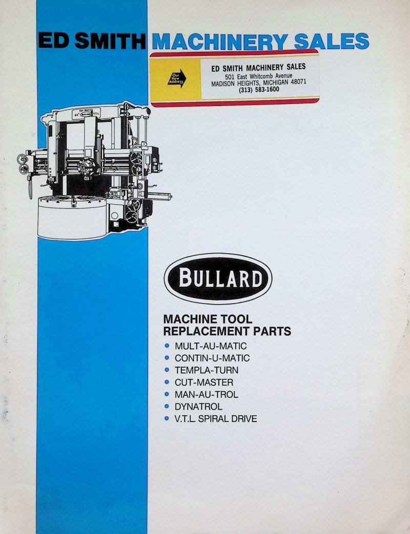
Bullard Machine Tool Replacement Parts List
Replacement parts list for Bullard machine tools, covering models Multi-Au-Matic, Contin-U-Matic, Templa-Turn, Cut-Master, Man-Au-Trol, Dynatrol, and V.T.L. Spiral Drive. This parts catalog details availability from a 7,000 sq. ft. warehouse with computerized inventory management and an additional 5,000 sq. ft. sub-assemblies facility—representing one of the largest Bullard parts stockings in the country. Includes specification and assembly information for clutch, headstock, and feedworks components essential for machine maintenance and repair.
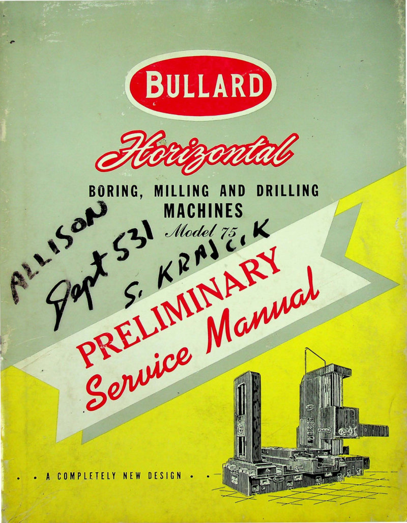
Bullard Model 75 Horizontal Boring Mill Service Manual
Preliminary service manual for the Bullard Model 75 horizontal boring mill, a precision machine tool designed for boring, milling and drilling operations. This workshop manual covers the complete mechanical and hydraulic architecture of the machine: general assembly drawings, head post counterweight and hydraulic assemblies, pendant control stations, feed mechanisms, headstock configuration, bed frame assemblies, oil distribution piping and guard systems, tank and table components, and rear post structure. Includes full electric and hydraulic schematic diagrams plus detailed wiring schematics for hydraulic circuits, pendant controls and cutting coolant delivery. Marked throughout as a completely new design from the manufacturer, making this repair manual essential for technicians maintaining or troubleshooting this model. Table of Contents: - GENERAL ASSEMBLY - Front and Right Side Section Elevations - Side Elevation – Right Hand - HEAD POST - Counterweight Bracket Assembly - Plan and Side Section - Hydraulic Counterweight Assembly - Section Elevation - Pendant Elevating Mechanism - PENDANT - Pendant and Headstock Control Unit - Feed Control Unit - FEED WORKS - Feed Bracket Unit - Rear, Front and Side Section Elevation - HEADSTOCK - Plan, Section Elevation and Rear View - Headstock and Feed Works - Left and Right Hand Elevation and Section Views - Feed and Traverse Take-Off Bracket Cover Assembly - Feed and Traverse Take-Off Bracket Unit - Bed Shafts, Feed and Traverse Take-Off Bracket Unit - OIL PIPING AND GUARD ASSEMBLY - Right Side - Plan View - Rear View - HEAD - Front and Plan View - Hydraulic Binder Assembly - Section Elevations - Section Elevations - Plan and Side Sections - Front View with Cover Removed and Side Section - Plan Section Thru Spindle Head and - Rock Feed Binder Assembly - TANK - Hydraulic Shifter Assembly - Shifter Cylinder Units - TABLE AND SADDLE - 54" X 92" Table and 48" X 132" Saddle Assembly - Saddle Gear Box for Plain Table - REAR POST - Left, Plan and Front Section Elevation - Left Side, Plan and Bottom Views - ELECTRIC AND HYDRAULIC - Schematic Diagram - WIRING DIAGRAM - Schematic Wiring Diagram for Hydraulic, Pendant and Cutting Coolant
Bullard Universal Boring Machine Instruction Manual
Instruction manual for the Bullard Universal 4 and 5 spindle horizontal boring, drilling, and milling machine. This comprehensive workshop manual covers initial uncrating and cleaning through complete operation and maintenance. Includes setup procedures such as mounting the head, preparing the foundation, levelling the machine, and reassembling spindle units. Details operating controls including the zero-speed or plugging switch, feed mechanisms to the spindle, and rapid traverse clutch adjustments. Extensive lubrication guidance covers oiling points throughout the machine, testing and conditioning of oils, feed friction and clutch adjustments, and spindle sleeve bearing maintenance. Provides detailed adjustment procedures for table and saddle gibs, rear post base and slide gibs, spindle feeding slide gibs, and head gibs to compensate for wear over time. Covers gearbox inspection and repair, threading attachment operation, V-belt alignment and tension, and rear post slide alignment. Includes a dedicated repair parts section with detailed technical drawings for reference and ordering. This service manual is essential for technicians performing routine maintenance, troubleshooting, and component replacement on these industrial boring machines. Table of Contents: - Uncrating, Cleaning, and Hanging Head - Foundation - Levelling - Re-Assembling 4" & 5" Spindle Bullard-Universal Boring Machine - Description of Operating Handles - Zero Speed or Plugging Switch - Operation of the Machine - Feed to Spindle - Oiling - Oiling Instructions - Testing Condition of Oils - Oiling Points - Table & Saddle Gibs Adjustments - Rear Post Base Gib Adjustments - Rear Post Slide Adjustments - Removing & Replacing Rear Post - Removing Gear Boxes for Inspection or Repair - Threading Attachment - Binders - Adjustments for Wear - Vee Belts Adjustment - Rapid Traverse Clutch Adjustment (Twin Disc) - Rapid Traverse Clutch Adjustment (Universal Cone Plate Type) - Feed Frictions Adjustment - Feed Clutch Adjustment - Spindle Sleeve Bearings Adjustment - Removing Sleeve from Head - Removing Bearings from Sleeve - Spindle Feeding Sleeve Bearing Adjustment - Rear Post Slides Alignment Adjustment - Spindle Feeding Sleeve Gib Adjustment - Head Gibs Adjustment - Repair Parts Section for 4" & 5" Bullard-Universal Horizontal Boring, Drilling and Milling Machines - Repair Parts Drawings
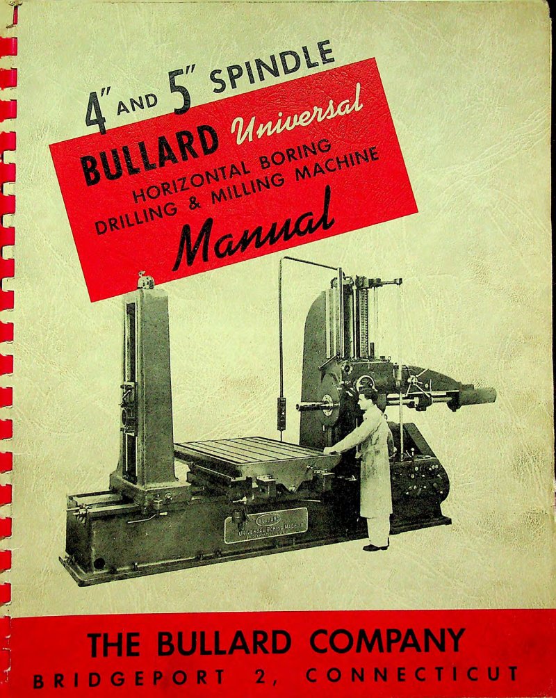
Bullard Universal Horizontal Boring, Drilling & Milling Machine Manual
Comprehensive workshop manual for Bullard Universal Horizontal Boring, Drilling and Milling Machines equipped with 4 inch and 5 inch spindles. This service manual covers the complete machine lifecycle from uncrating and installation through daily operation and long-term maintenance. Detailed sections address foundation requirements and levelling procedures essential for precision work, machine reassembly after transport, and a full walkthrough of operating handles with their exact locations on the machine. The manual provides clear instruction on machine operation and spindle feeding techniques, critical for achieving accuracy on production runs. Extensive coverage of the oiling systems and routine maintenance schedules helps operators keep the machine in peak condition. Includes practical guidance on bearing adjustments and clutch adjustments to restore original performance, plus a comprehensive parts list section with detailed technical drawings to support repair and component replacement. An indispensable reference for workshop technicians and machine operators responsible for setup, troubleshooting, and daily care of these versatile horizontal boring machines.
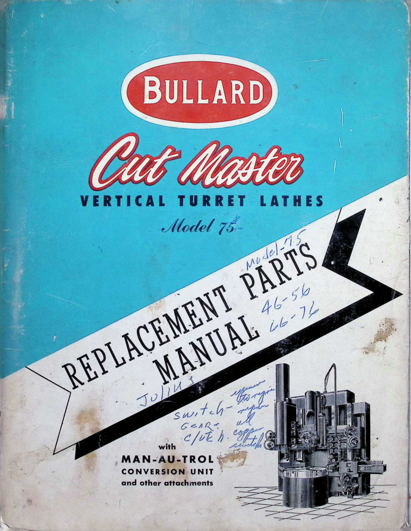
Cut Master Model 75 Vertical Turret Lathe Parts
Replacement parts manual for the Bullard Cut Master Model 75 vertical turret lathe, essential reference for operators and maintenance technicians working with 26", 36", 46", 56", 66", and 76" configurations. This comprehensive parts list covers standard machine components, the Man-Au-Trol conversion unit, and auxiliary attachments. Originally published by The Bullard Company in Bridgeport, Connecticut (1959), this workshop manual provides the detailed part identification and ordering information needed for repairs, maintenance, and rebuilds of these classic industrial lathes.
Cut Master Model 75 Vertical Turret Lathe Parts Manual
Replacement parts manual for Bullard Cut Master Model 75 vertical turret lathes, covering all standard sizes from 26" through 76" including the Man-Au-Trol conversion unit option. This 132-page parts list provides a pictorial index and detailed assembly component breakdowns essential for identifying and ordering replacement components. The manual includes comprehensive sections on the ram head, turret head, shaft housing, handwheel bracket assemblies, pendant controls, side head, handwheel mechanisms, table assemblies, and full lubrication and hydraulic schematic diagrams. Technicians and maintenance personnel will find the illustrated parts identification system invaluable for quick reference during repairs, rebuilds, or component replacement on these heavy-duty machine tools. Table of Contents: - RAM HEAD - RAIL RAISING ASSEMBLY - COUNTER-WEIGHT ASSEMBLY - SHAFT HOUSING - BED HOUSING - DRIVE SHAFTS TO RAM HEAD - TAKE-OFF BRACKETS - L.H. HANDWHEEL BRACKET UNIT - R.H. HANDWHEEL BRACKET UNIT - FEED CHART - PENDANT - TURRET HEAD - SIDE HEAD - HANDWHEEL UNIT - TABLES - TABLE SPEED CHART - SECTION THRU TABLE CARRIER - SECTION THRU MACHINE
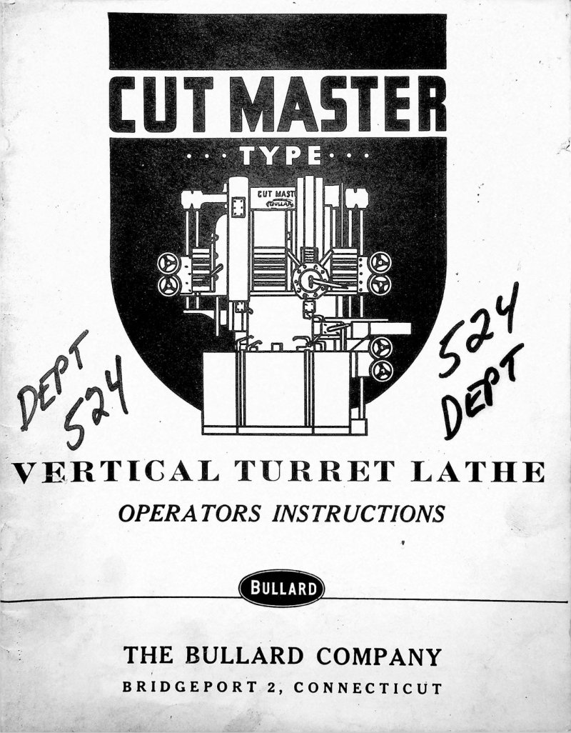
Cut Master Vertical Turret Lathe Operators Manual
Operators instruction book for the Bullard Cut Master Type Vertical Turret Lathe — a comprehensive workshop manual covering every aspect of machine operation, from initial installation and setup through daily operation and routine maintenance. The guide walks you through spindle operation, feed adjustment, and rail leveling procedures with practical clarity. Detailed sections address lubrication practices, automatic feed stops, spindle clutch and brake adjustment, and cutting speed selection using the included reference charts. Essential reference material for shop floor technicians operating this workhorse machine tool. Published by The Bullard Company, Bridgeport, Connecticut.
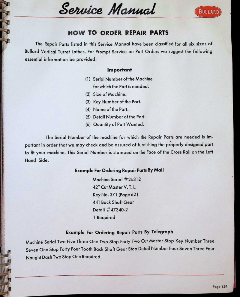
Cut Master Vertical Turret Lathe Parts List
Comprehensive parts list and cross-reference for Bullard Cut Master Vertical Turret Lathe, covering all six machine sizes. This repair manual section details every replacement part by key number, part name, and drawing reference, making it straightforward to identify and order the exact component you need. Pages 129–131 focus on the parts cross-reference, covering essential drivetrain and transmission components including cone drive shafts, traverse gears, feed clutches, center gears, miter gears, and the various bushings and retainers that support the turret's operation. The guide also walks you through the ordering process with worked examples for both mail and telegraph orders, so you can source parts efficiently whether you're restocking a single item or planning major maintenance on your lathe.
Cut Master Vertical Turret Lathe Service Manual
Comprehensive service manual for the Bullard Cut Master Vertical Turret Lathe, second edition. This workshop manual provides detailed operating instructions, systematic maintenance procedures, troubleshooting guidance, and a complete parts list for service and repair work. Published by The Bullard Company of Bridgeport, Connecticut, this 192-page reference covers the essential information needed for proper operation and upkeep of this precision turret lathe. Ideal for shop technicians and equipment operators seeking authoritative documentation on the Cut Master model. Table of Contents: - Adjustable Automatic Feed Stops - Adjustment—Clutch and Brake - Adjustment—Cross Rail Leveling - Adjustment—Traverse Friction Clutch - Adjustment—Vertical Feed Nut - Angle Turning Chart - Angle Turning with T.D.A. - Angle Turning without Attachments - Assembling the Machine - Brake and Clutch Adjustment - Capacities—Lubricating Oil Reservoir - Char—Cutting Speed - Cleaning the Machine - Clutch and Brake Adjustment - Coolant—Cutting - Cross Rail Leveling Adjustment - Cross Rail — Raising and lowering - Cutting Coolant System - Cutting Speed Chart - Damage in Shipment - Disk — Micrometer - Drum Scoring Chart—English (with Special Headstock Ratio 1:1) - Drum Scoring Chart—English Using "J" feed - Drum Scoring Chart—Metric - Drum Scoring with T.D.A. - English Drum Scoring Chart (with Special Headstock Ratio 1:1) - English Drum Scoring Chart Using "J" feed - English Thread Cutting Chart - Feed and Traverse Levers - Feed Change Pull Pins - Feed Nut — Adjustment - Feed — Safety Coupling - Feed Stops—Automatic Feed - Feed Stops—Ram Head - Feed Stops—Side Head - Feed Stops—Turret Head - Feed, Traverse and Rail Raising Safety Coupling - Foreign Shipment - Foundation - Hammer Head Wheels - Headstock—Swiveling the Rail - Headstock - Indexing the Turret - Installation - Installation — Preparing for - Installing the Lubricants - Jacking & Rolling On Skids - Leveling—Cross Rail Adjustment - Leveling the Machine - Levers—Feed & Traverse - Lifting with Crane - Lowering and Raising the Cross Rail - Lubricants — Installing the - Lubricant Specifications - Lubricating Oil Reservoir Capacities - Lubrication - Machine Assembling - Machine — Cleaning - Machine — Leveling - Machine — Operating the - Machine — Starting - Machine Weights - Metric Drum Scoring Chart - Metric Thread Cutting Chart - Micrometer Disk & Scales - Operating the Machine - Operating the T.D.A. Attachment - Preparing for Installation - Pull Pins — Feed Change - Rail Raising — Safety Coupling - Raising & Lowering the Cross Rail - Ram Head—Automatic Feed Stops - Receiving - Repair Parts Section - Rolling & Jacking On Skids - Safety Coupling — Feed - Safety Coupling — Rail Raising - Safety Coupling — Traverse - Scales - Shipment and Transit - Shipment — Damage in - Shipment — Foreign - Side Head — Automatic Feed Stops - Specifications — Lubricant - Starting the Machine - Suggested Lubrication Maintenance System - Swiveling the Rail Heads - T.D.A. Attachment - T.D.A. Attachment—Operation of - Testing Condition of Oils - Thread Cutting Chart—English - Thread Cutting Chart—Metric - Thread Cutting Chart with T.D.A. - Traverse Friction Clutch Adjustment - Traverse — Safety Coupling - Turret Head — Automatic Feed Stops - Turret Indexing - Vertical Feed Nut Adjustment - Weights of Machine - Wheels — Hammer Hand
Dynatrol Vertical Turret Lathe Feed Bracket Service Manual
Service bulletin S.B. #10-D for the Dynatrol Vertical Turret Lathe Variable Speed Feed Bracket. This service manual covers operational principles and essential adjustment procedures for both manually operated and portable pendant-controlled feed brackets. It details the functional control units and critical components—V.D. and C.D. Pumps, Servo Cam, Servo Valve, High Speed 3-Way Valve, and Feed Integrator Discs—along with maintenance and troubleshooting guidance for each system. Designed for authorized service agents, sales personnel, field service representatives, and maintenance departments responsible for Bullard lathe equipment.
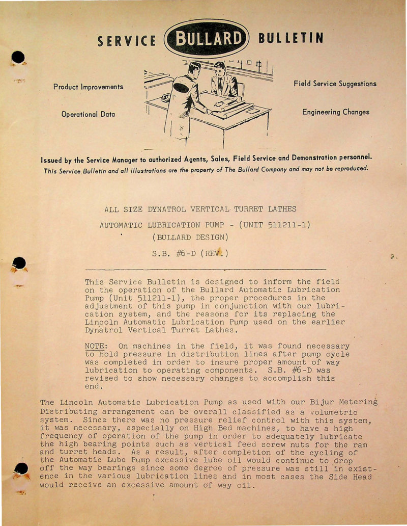
Dynatrol Vertical Turret Lathe Lube Pump Service Manual
Service manual for the Bullard Automatic Lubrication Pump (Unit 511211-1), engineered for all sizes of Dynatrol Vertical Turret Lathes. This workshop manual covers complete operation and adjustment of the pressure-controlled lubrication system, including solenoid valve configuration and pressure switch settings calibrated to approximately 200 P.S.I. The manual explains the advantages of the Bullard pump design over the earlier Lincoln pump installation, detailing how excess oil automatically returns to the reservoir. Includes operational sequences, comprehensive electrical and hydraulic schematic diagrams, and step-by-step adjustment procedures for distributing proper lubrication to all bearing points on the machine. Bulletin S.B. #6-D (Revised).
Dynatrol Vertical Turret Lathe Parts List
Bullard Dynatrol vertical turret lathe parts list covering all three machine sizes—26-36-46, 56-66-76-86, and 108-124-144 inches. This replacement parts manual features a pictorial index and exploded views for each configuration, making it straightforward to identify and order the correct components for maintenance and repair work across the full Dynatrol range. Table of Contents: - REPLACEMENT PARTS MANUAL - DYNATROL - vertical turret lathes - PICTORIAL INDEX - PICTORIAL INDEX - PICTORIAL INDEX
Dynatrol Vertical Turret Lathe Variable Speed Feed Bracket Manual
Service manual for the Standard Feed Bracket (infinite feed type) fitted to Bullard Dynatrol Vertical Turret Lathes. This workshop manual covers complete feedworks operation, explaining variable-speed drive options and the operation of variable delivery piston pumps used in the transmission system. Detailed sections address hydro-mechanical transmission principles, yoke control servomechanism design, directional clutch operation, high-speed 3-way valve function, formsprag clutch behavior, and both directional and feed control systems. Includes general description of the feed bracket assembly, feedworks schematic diagrams, and step-by-step adjustment instructions for manual feed bracket setup and portable pendant control configuration. An essential repair reference for technicians servicing Dynatrol lathe feed systems. Table of Contents: - TYPES OF DRIVES - CHIEF CHARACTERISTICS - VARIABLE DELIVERY PISTON PUMPS - SIMPLE HYDRO-MECHANICAL TRANSMISSION - BULLARD HYDRO-MECHNICAL TRANSMISSION-(FEED WORKS) OPERATING PRINCIPLES - YOKE CONTROL (SERVOMECHANISM) - DIRECTIONAL CLUTCH - HIGH SPEED 3-WAY VALVE - FORMSPRAG CLUTCH - DIRECTIONAL CONTROL - FEED CONTROL - GENERAL DESCRIPTION - FEED WORKS SCHEMATIC - ADJUSTMENT INSTRUCTIONS - MANUAL FEED BRACKET - PORTABLE PENDANT CONTROL
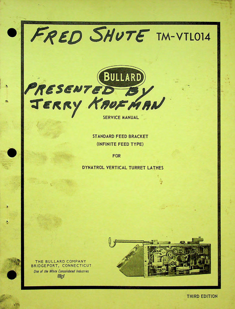
Dynatrol VTL Feed Bracket Service Manual
Service manual for the Bullard Dynatrol Vertical Turret Lathe Standard Feed Bracket (Infinite Feed Type). This workshop manual covers the complete hydraulic and mechanical systems: variable displacement piston pumps, hydro-mechanical transmission operation, yoke control servomechanism, directional clutch assembly, high-speed 3-way valve function, formsprag clutch behavior, and directional and feed control mechanisms. Includes detailed adjustment procedures for feed bracket setup and operation, feed works schematics, and portable pendant control documentation for manual feed bracket operation. Essential reference for technicians performing maintenance, troubleshooting, or repair on Dynatrol feed bracket systems. Table of Contents: - INTRODUCTION - TYPES OF DRIVES - CHIEF CHARACTERISTICS - VARIABLE DELIVERY PISTON PUMPS - SIMPLE HYDRO-MECHANICAL TRANSMISSION - BULLARD HYDRO-MECHANICAL TRANSMISSION-(FEED WORKS) OPERATING PRINCIPLES - YOKE CONTROL (SERVOMECHANISM) - DIRECTIONAL CLUTCH - HIGH SPEED 3-WAY VALVE - FORMSPRAG CLUTCH - DIRECTIONAL CONTROL - FEED CONTROL - GENERAL DESCRIPTION - FEED WORKS SCHEMATIC - ADJUSTMENT INSTRUCTIONS - MANUAL FEED BRACKET - PORTABLE PENDANT CONTROL
Dynatrol VTL Variable Speed Feed Bracket Manual
Service bulletin S.B. #10-D for the Dynatrol Vertical Turret Lathe Variable Speed Feed Bracket system. This workshop manual covers operation and required adjustments for both manual and portable pendant-controlled feed brackets. Includes detailed procedures for V.D. and C.D. pumps, servo cam, servo valve, high-speed 3-way valve, and feed integrator discs. Contains adjustment procedures and operational instructions with illustrated diagrams to guide technicians through setup, calibration, and troubleshooting of the variable speed feed mechanism.
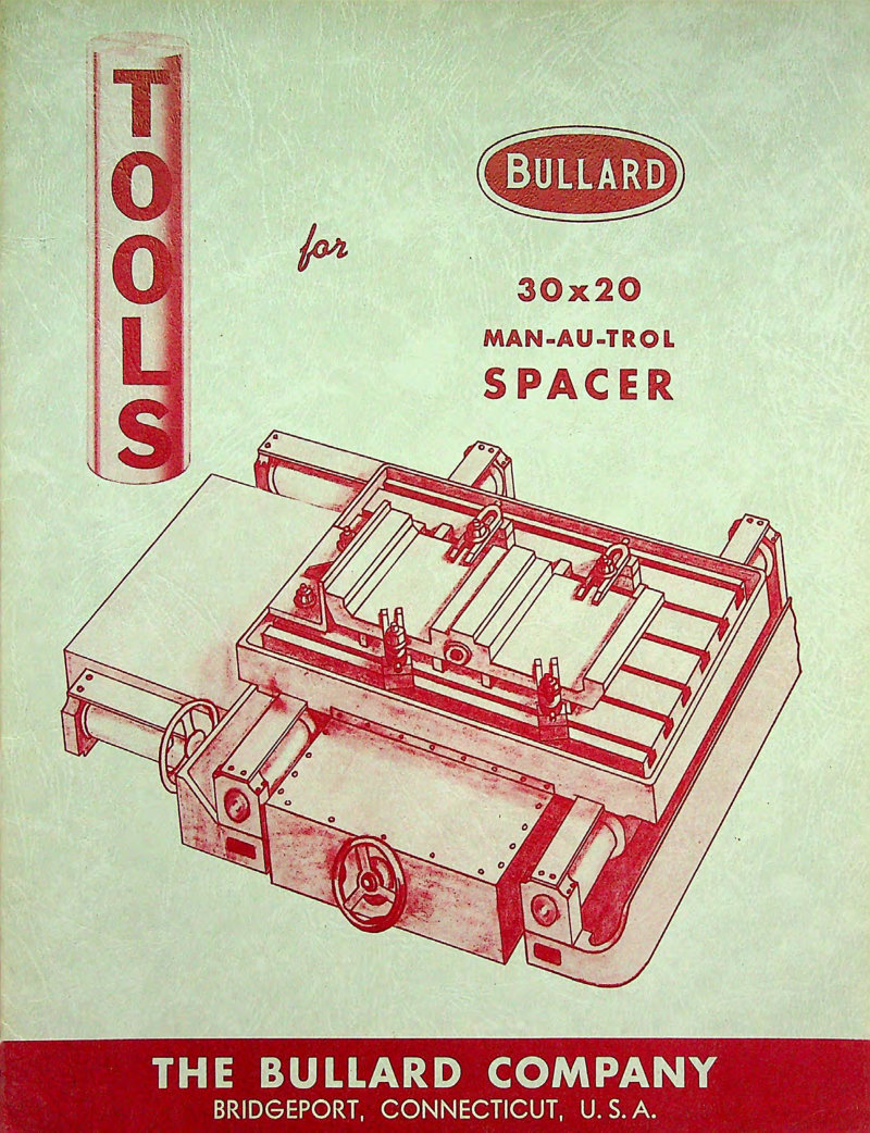
Man-Au-Trol 30x20 Spacer Parts List
Complete parts list and tool equipment catalog for the Bullard Man-Au-Trol 30x20 Spacer precision machine. Features a comprehensive component index and detailed breakdown of the standard tool equipment set, including T-bolts, center drills, angle plates, parallels, adjustable jacks, U-clamps, stop blocks, and accessories. Each tool and component is illustrated with technical drawings for accurate identification and ordering. Essential reference for maintenance, repair, and machine setup.
Man-Au-Trol Vertical Turret Lathe Instructions Manual
First edition temporary supplement instruction and parts manual for the Bullard Man-Au-Trol vertical turret lathe. This workshop manual provides technical specifications for the automatic spindle feed system, including motor amperage ratings and operating ranges. Includes mechanical assembly drawings and component layout diagrams presented in side view profile, essential for understanding the machine's structure and maintenance requirements.
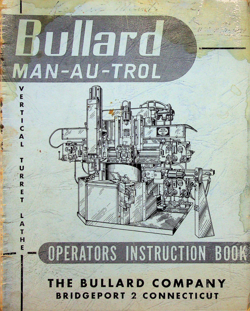
Man-Au-Trol Vertical Turret Lathe Operators Manual
Operators instruction manual for the Bullard Man-Au-Trol vertical turret lathe, published by The Bullard Company, Bridgeport, Connecticut in 1953. This workshop guide covers essential operating procedures and practical techniques for safely and efficiently running the machine. Document reference MANO.1—6-53 3M.
Man-Au-Trol Vertical Turret Lathe Service Manual
Service manual for the Bullard Man-Au-Trol Vertical Turret Lathe, an essential workshop reference prepared by The Bullard Company of Bridgeport, Connecticut. This repair manual covers complete operating instructions, detailed maintenance procedures, and comprehensive repair parts information to help machine operators and maintenance personnel master the lathe's automatic operation features and keep it running reliably. Whether you're setting up the machine, diagnosing issues, or performing routine service, this technical documentation provides the guidance you need for safe and efficient operation. Table of Contents: - Adjustment—Clutch and Brake - Adjustment—Cross Rail Leveling - Angular Turning Attachment Type "A" - Angular Turning Attachment Type "B" - Assembling the Machine - Attachment—Angular Turning Type "A" - Attachment—Angular Turning Type "B" - Capacities—Cutting Coolant Reservoir - Capacities—Lubrication Oil Reservoir - Care of Man-Au-Trol Switches - Chart—Cutting Speed - Chart—Table Speed - Clean the Machine - Clutch and Brake Adjustment - Couplings—Feed, Traverse and Rail Raising Safety - Cross Rail Leveling Adjustment - Cross Rail—Raising and Lowering - Cutting Coolant Reservoir Capacities - Cutting Coolant System - Cutting Speed Chart - Damage in Shipment - Dials—Micrometer - Detection Setting for Main Head - Detector Setting for Side Head - Description—Machine General - Feed Bracket and Man-Au-Trol Unit - Feed, Traverse and Rail Raising Safety Couplings - Foreign Shipment - Foundation - Function Drum Set Up for Main Head - Function Drum Set Up for Side Head - General Description - Hand Cranks - Head Shock - How to Order Repair Parts - How Man-Au-Trol Operates - Hydraulic (Unloading Valve) System - Index—Turret - Installation - Installing the Lubricants - Important Caution Notes - Jacking and Rolling on Skids - Lever—Manual—Automatic Position - Lever—Manual—Control - Leveling the Machine - Lifting with Crane - Lubrication - Lubrication—Installing the Lubricants - Lubrication—Oil Reservoir Capacities - Lubrication Specifications - Machine Approx. Net Weights - Machine—Assembling - Machine—Cleaning - Machine—General Description - Machine—Leveling - Machine—Starting - Machine—Wiring - Main Head—Detector Setting - Main Head—Start - Manual—Automatic Position Lever - Manual—Control Lever - Micrometer Dials and Scales - Overrunning Clutch—Ram and Turret Head - Preparing for Installation - Raising and Lowering the Cross Rail - Ram Head Overrunning Clutch - Ram Head—Swiveling - Ram and Turret Head Overrunning Clutch - Receiving - Repair Parts—How to Order - Repair Parts Section - Rolling and Jacking on Skids - Scales - Set Up—Main Head Function Drum - Set Up Procedure for Automatic Production - Set Up—Side Head Function Drum - Shipment—Damage in - Shipment—Foreign - Shipment and Transit - Side Head—Detector Setting - Side Head—Start - Specifications—Lubrication - Speed—Table Change - Start Side Head and Start Main Head - Starting the Man-Au-Trol V.T.L. - Suggested Lubrication Maintenance System - Switches—Care of Man-Au-Trol - Swiveling the Ram Heads - Table Speed Change - Table Speeds Chart - Testing the Condition of Oils - Turret Head Overrunning Clutch - Turret Index - Weights—Machine Approx. Net - Wiring the Machine
Man-Au-Trol Vertical Turret Lathe Service Manual
Service manual for the Bullard Man-Au-Trol 42-inch vertical turret lathe. This comprehensive workshop reference covers operating instructions, maintenance procedures, and repair parts information. The manual documents the fundamental principles of vertical turret lathe design and the automatic operation features developed by Bullard Company in Bridgeport, Connecticut. It includes detailed guidance on machine setup, operation, and troubleshooting for technicians and shop personnel. Originally published in 1953, this PDF serves as an essential technical reference and parts list for maintaining and servicing this classic industrial lathe. Table of Contents: - Adjustment—Clutch and Brake - Adjustment—Cross Rail Leveling - Angular Turning Attachment Type "A" - Angular Turning Attachment Type "B" - Assembling the Machine - Attachment—Angular Turning Type "A" - Attachment—Angular Turning Type "B" - Capacities—Cutting Coolant Reservoir - Capacities—Lubrication Oil Reservoir - Care of Man-Au-Trol Switches - Chart—Cutting Speed - Chart—Cutting Speed - Clean the Machine - Clutch and Brake Adjustment - Couplings—Feed, Traverse and Rail Raising Safety - Cross Rail Leveling Adjustment - Cross Rail—Raising and Lowering - Cutting Coolant Reservoir Capacities - Cutting Coolant System - Cutting Speed Chart - Dials—Micrometer - Detector Setting for Main Head - Detector Setting for Side Head - Description—Machine General - Feed Bracket and Man-Au-Trol Unit - Foreign Shipment - Foundation - Function Drum Set Up for Main Head - Function Drum Set Up for Side Head - General Description - Hand Cranks - Hand Stock - How to Order Repair Parts - How Man-Au-Trol Operates - Hydraulic (Unloading Valve) System - Index—Turret - Installation - Installation—Preparing for - Installing the Lubricants - Important Caution Notes - Jacking and Rolling on Skids - Lever—Manual—Automatic Position - Leveling the Machine - Lifting with Crane - Lubrication - Lubrication—Installing the - Lubrication Oil Reservoir Capacities - Lubrication Specifications - Machine Approx. Net Weights - Machine—Assembling - Machine—Cleaning - Machine—General Description - Machine—Leveling - Machine—Starting - Machine—Wiring - Main Head—Detector Setting - Main Head—Shaft - Manual—Automatic Position Lever - Manual—Control Lever - Micrometer Dials and Scales - Overrunning Clutch—Ram and Turret Head - Preparing for Installation - Raising and Lowering the Cross Rail - Ram Head Overrunning Clutch - Ram Head—Swiveling - Ram and Turret Head Overrunning Clutch - Receiving - Repair Parts—How to Order - Repair Parts Section - Rolling and Jacking on Skids - Scales - Set Up—Main Head Function Drum - Set Up Procedure for Automatic Production - Set Up—Side Head Function Drum - Shipment—Damage in - Shipment—Foreign - Shipment and Transit - Side Head—Detector Setting - Side Head—Shaft - Specifications—Lubrication - Speed—Table Change - Start Side Head and Shut Off Main Head - Starting the Man-Au-Trol V.T.L - Suggested Lubrication Maintenance System - Switches—Care of Man-Au-Trol - Swiveling the Ram Heads - Table Speed Change - Table Speeds Chart - Testing the Condition of Oils - Turret Head Overrunning Clutch - Turret Index - Weights—Machine Approx. Net - Wiring the Machine
Type D Mult-Au-Matics Service Manual
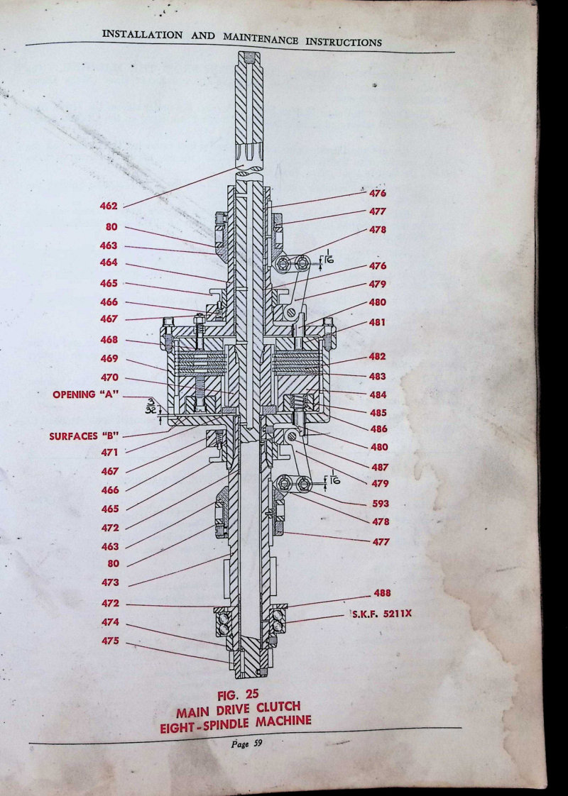
Installation and maintenance instructions for Bullard Type D Mult-Au-Matics eight-spindle and six-spindle automatic machines. This service manual provides detailed technical drawings of main drive clutch assemblies with numbered component diagrams (Fig. 25 for eight-spindle and Fig. 26 for six-spindle configurations), step-by-step removal procedures for clutch components, and comprehensive parts lists with part numbers. Covers clutch shaft units, toggle mechanisms, brake assemblies, and associated hardware. Essential reference for technicians performing maintenance, troubleshooting, and repair work on these precision production machines.
Type D Mult-Au-Matics Service Manual
Service manual for the Bullard Type D Mult-Au-Matics automatic chucking machine. This workshop manual covers installation procedures, routine maintenance schedules, and repair operations for this precision industrial equipment. Includes a comprehensive technical diagram detailing all major assemblies: drive motor, feed works, timing disk, clutch shift lever, index control lever, tool carrying head, chip guards, work spindle, loading station, and chuck operator lever. Essential reference for technicians performing setup, troubleshooting, and parts replacement on this automatic chucking system. Published by The Bullard Company, Bridgeport, Connecticut. Table of Contents: - Bracket (Drive) - Capacity Charts - 6-Spindle Machines (Dove Tail Ways) - 8-Spindle Machines (Dove Tail Ways) - 6-Spindle Machines (Square Lock Ways) - 8-Spindle Machines (Square Lock Ways) - Chip Receiver - Chuck Jaw Pressure Chart - Chuck Operator (Power) - Single - Double - Chuck Pressure Chart (Heavy Duty) - Chucks - Hand Operated - Power Operated - Clutch - Main Drive - 6-Spindle Machines - 8-Spindle Machines - Control and Index Interlock - Control (Two Pin) - Coolant Tank - Counterweighing - Cross Compound Head - Cutting Lubricant System - Cycle Chart (Index) - Diagrams - Feed Works Function - Electrical - 6-Spindle Machines - 8-Spindle Machines - Wiring Diagram - Disc. Timing - Double Index Chuck Operator - Double Index Mechanism - Double Purpose Head - Drive Bracket - Drive Clutch (Main) - 6-Spindle Machines - 8-Spindle Machines - Feed and Speed Plates - 8" 6 and 8-Spindle Machines - 12" 6 and 8-Spindle Machines - 16" 6-Spindle Machines - 16" 8-Spindle Machines - 16-23" 8-Spindle Machines - Feed Works - 6 or 8-Spindle Machines - Hand Operated Chucks - Heads - Standard Cross Compound - Standard Double Purpose - Standard Plain - Standard Universal - Vertical Compound - Index Control Interlock - Index Cycle Chart - Index Mechanism - Single—6-Spindle Machines - Single—8-Spindle Machines - Double—6-Spindle Machines - 8-Spindle Machines - Installation Diagrams - 6-Spindle Machines - 8-Spindle Machines - Interlock (Control and Index) - Jaw Pressure Chart - Lifting Machine - Lubricant (Cutting) - Lubrication System - Main Drive Clutch - 6-Spindle Machines - 8-Spindle Machines - Oiling System - Plain Band - Power Chuck Operator - Double - Heavy Duty - Single - Standard - Power Operated Chucks - Pressure Charts - Settling Tank - Single Index Chuck Operator - Single Index Mechanism - Sliding Pinion and Fork - Slinging Machine - Speed and Feed Plates - 8" 6 and 8-Spindle Machines - 12" 6 and 8-Spindle Machines - 16" 6-Spindle Machines - 16" 8-Spindle Machines - 16-23" 8-Spindle Machines - Spindle - 8" and 12" Machines - 16" Machines - Timing Disc - Two Pin Controller - Universal Head - Vertical Compound Head - Wiring Diagram
Type D Mult-Au-Matics Service Manual
Service and maintenance manual for the Bullard Type D Mult-Au-Matics automatic machine tool, covering both 6-spindle and 8-spindle configurations. Provides detailed installation guidance and operational procedures with comprehensive diagrams illustrating the drive motor, drive bracket, timing disc, clutch shift lever, index control lever, tool carrying head, work spindle, and chip cutting lubricant system. Includes technical specifications and an index to all illustrations for quick reference during setup and troubleshooting.
Vertical Turret Lathe 36-Inch Parts List
Comprehensive parts list for the Bullard 36-inch vertical turret lathe, designed for ordering replacement components and locating parts by serial number. The manual includes a foreword with ordering procedures and guidance on identifying your machine's serial number location. Detailed part numbering covers the bed division assembly and spindle components, including the water guard, table spindle, eye bolt, manhole cover, dust cap, spindle bushings, felt retainers, thrust washers, wiper seals, and the full range of screws and fasteners needed for maintenance and repair. Essential reference for workshop technicians and machine operators maintaining this classic industrial lathe.
Vertical Turret Lathe Operator's Handbook
Operators handbook and comprehensive instructions for Bullard Vertical Turret Lathes with Spiral Drive. Published by The Bullard Company, Bridgeport, Connecticut. This workshop manual covers machine operation, maintenance procedures, lubrication systems, cutting fluid equipment setup, and detailed adjustment protocols. The manual provides complete guidance on initial setup and installation, main and side head operation, brake system adjustments, startup procedures, and machine leveling techniques. Includes an extensive index for quick reference across all operational and maintenance topics.
Vertical Turret Lathe Spiral Drive Type Operators Handbook
Operators handbook and workshop instructions for Bullard Vertical Turret Lathes equipped with Spiral Drive Type transmission. This 28-page manual from The Bullard Company, Bridgeport, Connecticut, covers essential operation and maintenance procedures for these robust production machines. Includes a detailed front view diagram identifying all hand oiling points across the lathe assembly to help operators maintain proper lubrication schedules and extend equipment service life. Practical reference for daily operation, setup, and routine upkeep of Bullard vertical turret lathes in the shop.
Vertical Turret Lathes Spiral Drive Operator's Manual
Operator's manual for Bullard Vertical Turret Lathes with Spiral Drive, published by The Bullard Company of Bridgeport, Connecticut. This workshop manual serves as a comprehensive guide for machine operators seeking to master the capabilities and performance of these heavy-duty vertical turret machines. The introduction covers fundamental advances in machine shop practice and explains how Bullard's design delivers universal adaptability for varied production work. Key operational features discussed include simultaneous operation of main and side heads, the vertical spindle orientation with horizontal worktable plane that simplifies workholding and access, and the structural rigidity engineered to handle both heavy cutting forces and sustained high-speed operation. The handbook details the centralized control layout, lubrication systems essential for reliable performance, and rapid changeover procedures that maximize productivity. Emphasis throughout is placed on dependability and efficient production output, making this an invaluable reference for operators and maintenance personnel looking to optimize machine utilization and workflow.
Vertical Turret Lathes Spiral Drive Type Manual
Operators handbook and complete service instructions for Bullard Vertical Turret Lathes equipped with Spiral Drive transmission. Published by The Bullard Company, Bridgeport, Connecticut. This workshop manual covers operation, maintenance, and troubleshooting procedures for the Spiral Drive Type vertical turret lathe platform. Original documentation from industrial archives.