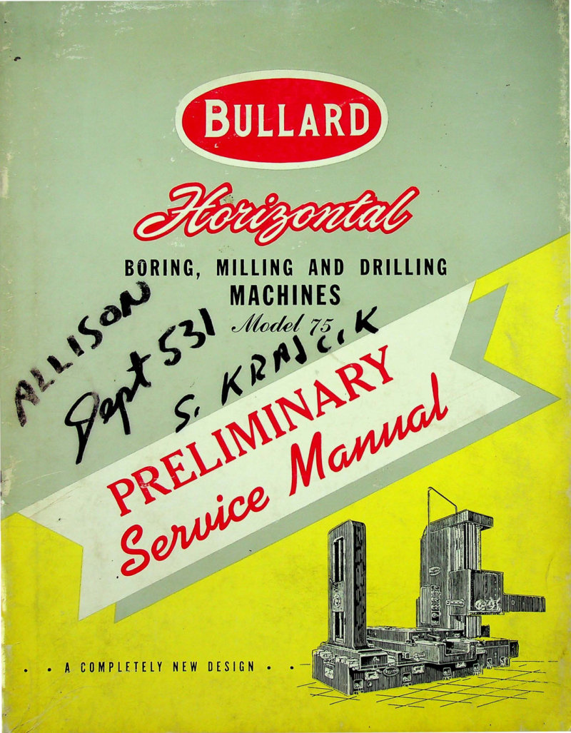
Bullard Model 75 Horizontal Boring Mill Service Manual
Preliminary service manual for the Bullard Model 75 horizontal boring mill, a precision machine tool designed for boring, milling and drilling operations. This workshop manual covers the complete mechanical and hydraulic architecture of the machine: general assembly drawings, head post counterweight and hydraulic assemblies, pendant control stations, feed mechanisms, headstock configuration, bed frame assemblies, oil distribution piping and guard systems, tank and table components, and rear post structure. Includes full electric and hydraulic schematic diagrams plus detailed wiring schematics for hydraulic circuits, pendant controls and cutting coolant delivery. Marked throughout as a completely new design from the manufacturer, making this repair manual essential for technicians maintaining or troubleshooting this model.
Table of Contents:
- GENERAL ASSEMBLY
- Front and Right Side Section Elevations
- Side Elevation – Right Hand
- HEAD POST
- Counterweight Bracket Assembly
- Plan and Side Section
- Hydraulic Counterweight Assembly
- Section Elevation
- Pendant Elevating Mechanism
- PENDANT
- Pendant and Headstock Control Unit
- Feed Control Unit
- FEED WORKS
- Feed Bracket Unit
- Rear, Front and Side Section Elevation
- HEADSTOCK
- Plan, Section Elevation and Rear View
- Headstock and Feed Works
- Left and Right Hand Elevation and Section Views
- Feed and Traverse Take-Off Bracket Cover Assembly
- Feed and Traverse Take-Off Bracket Unit
- Bed Shafts, Feed and Traverse Take-Off Bracket Unit
- OIL PIPING AND GUARD ASSEMBLY
- Right Side
- Plan View
- Rear View
- HEAD
- Front and Plan View
- Hydraulic Binder Assembly
- Section Elevations
- Section Elevations
- Plan and Side Sections
- Front View with Cover Removed and Side Section
- Plan Section Thru Spindle Head and
- Rock Feed Binder Assembly
- TANK
- Hydraulic Shifter Assembly
- Shifter Cylinder Units
- TABLE AND SADDLE
- 54" X 92" Table and 48" X 132" Saddle Assembly
- Saddle Gear Box for Plain Table
- REAR POST
- Left, Plan and Front Section Elevation
- Left Side, Plan and Bottom Views
- ELECTRIC AND HYDRAULIC
- Schematic Diagram
- WIRING DIAGRAM
- Schematic Wiring Diagram for Hydraulic, Pendant and Cutting Coolant
Documentation must be downloaded on a computer (PC, Mac, or Linux).
Do not use a smartphone or tablet to download documentation; they generally lack sufficient memory capacity to handle large files, and few users know how to locate the download folder on these devices.
Once downloaded, you can use it right away and even print the pages you need, or use your smartphone in photo mode to translate into the language of your choice: Google Translate
Document Details
- Format
- Pages
- 67
- Size
- 22.5 MB
- Category
- Machine Tools