HARDINGE - Service Manuals
53 manuals available for download
Hardinge is a trusted manufacturer of precision machine tools and automatic screw machines built for demanding manufacturing environments. Our comprehensive catalog includes original service manuals, repair guides, operator's manuals and detailed parts lists available as PDF downloads to support maintenance, troubleshooting and workshop operations. Whether you need technical documentation for bar feeds, chucking machines, or precision lathes, Hardinge's resource library provides the owner's manual and maintenance guidance required to keep your equipment running at peak performance.
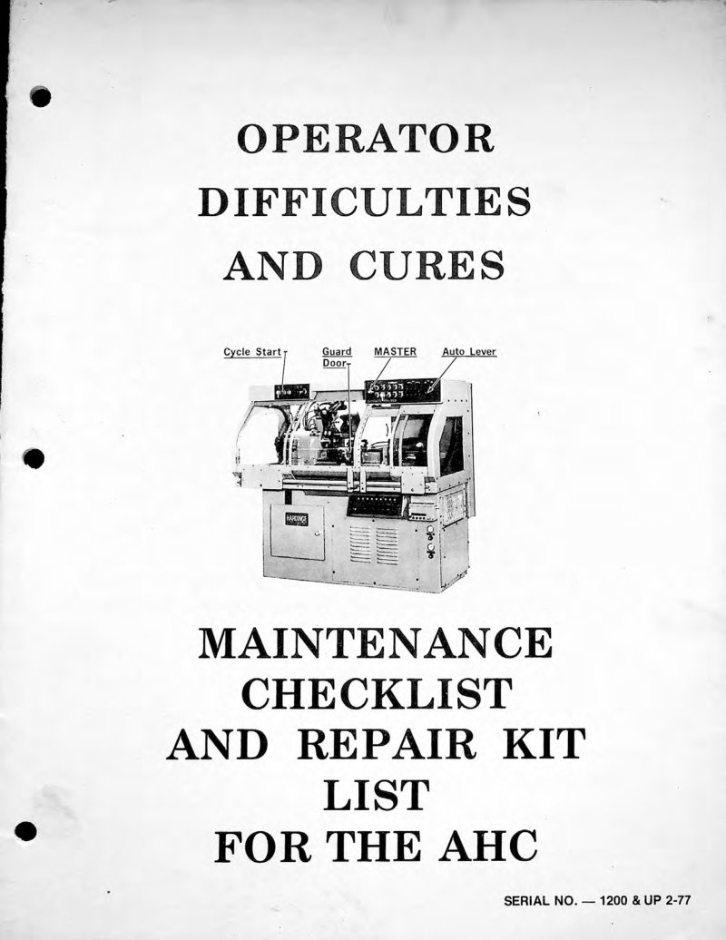
AHC Lathe Troubleshooting Service Manual
Troubleshooting service manual for the Hardinge AHC automatic lathe (Serial No. 1200 and up). This workshop guide provides systematic diagnostic procedures and field-proven remedies for common operational issues across all major machine functions—cycle start failures, collet closer operation, cross slide movement, carriage indexing, spindle performance, threading unit faults, turret positioning, and taper function problems. Organized as 17 numbered troubleshooting items, each with clear diagnostic steps and practical corrections. Essential reference for machine operators and maintenance technicians needing to restore full performance quickly and minimize downtime.
ASM-5C Automatic Screw Machine Operator's Manual
Operator's manual for the Hardinge ASM-5C Automatic Super-Precision screw machine. This repair and maintenance guide covers essential setup procedures including machine leveling, thorough cleaning protocols, hydraulic system priming, and reservoir filling (22 gallons capacity for later production models). Technical diagrams illustrate oil level gauge location and the hydraulic pump priming sequence, providing hands-on reference for initial operation and routine maintenance. Comprehensive resource for machine operators and technicians responsible for day-to-day setup and troubleshooting.
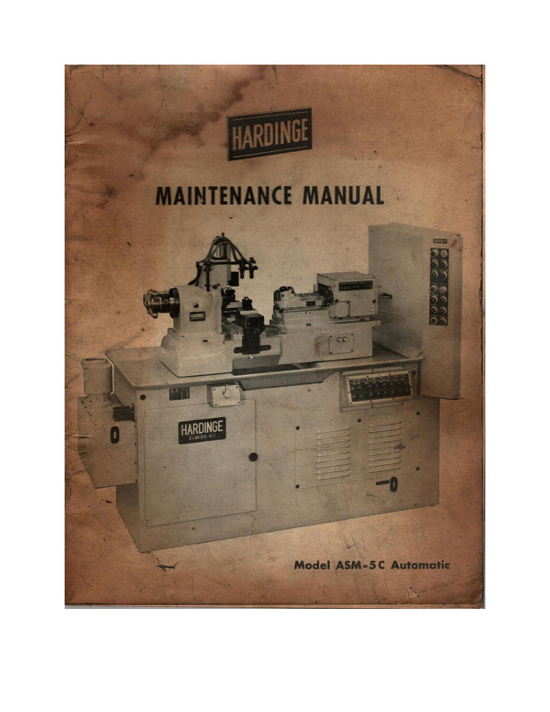
ASM-5C Automatic Screw Machine Service Manual
Comprehensive service manual for the Hardinge ASM-5C automatic screw machine, providing detailed guidance for technicians and operators performing maintenance and repair work. Covers systematic disassembly and reassembly of the clutch shaft and brake assembly, coolant system management including reservoir and cooling fan maintenance, adjustment and removal of cross slides for precision repositioning, headstock removal and installation procedures, hydraulic oil reservoir operation and valve compartment access, spindle bearing and motor lubrication protocols, spindle belt tensioning and replacement, turret disassembly with gib and index lock calibration, vertical slide feed valve and pressure switch setup, and comprehensive preventive maintenance schedules. Essential for workshop operations and machine longevity.
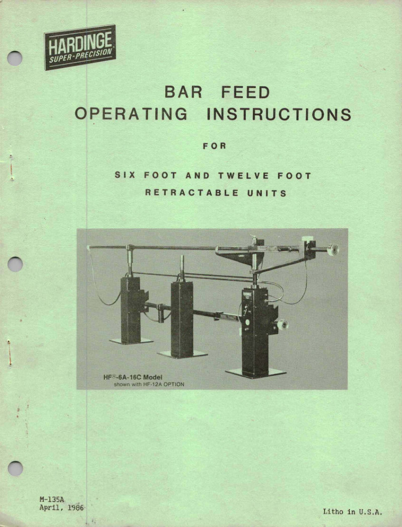
Bar Feed Operating Instructions M-135A
Operating instructions for Hardinge Super-Precision Bar Feed units, model M-135A, covering six foot and twelve foot retractable units (HF-6A-16C model shown with HF-12A option). This workshop manual provides essential safety recommendations, operational guidelines, and maintenance procedures for proper setup and daily operation of automatic bar feed equipment. Includes troubleshooting guidance and care instructions to keep the feed mechanism running smoothly. Dated April 1986. Valuable reference for machine shop technicians and equipment operators responsible for CNC lathe bar feeding systems.
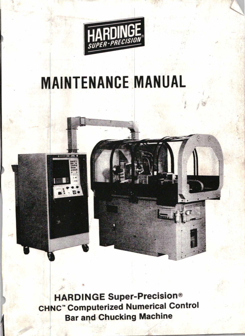
CHNC Bar and Chucking Machine Maintenance Manual
Maintenance manual for the Hardinge Super-Precision CHNC computerized numerical control bar and chucking machine. This workshop manual provides comprehensive maintenance procedures, safety recommendations, and operational guidelines essential for proper equipment care and longevity. The service manual covers equipment grounding and electrical safety protocols, including proper disconnection procedures before maintenance work, personal protective equipment requirements, guarding and door security measures, safe handling of chemical and flammable materials, and fire extinguisher placement and requirements. Additional sections address practical machine operation and setup: tool clamping procedures, awareness of pinch points during operation, turret tool handling and safety, chuck inspection and maintenance, tool mounting surface preparation, and correct installation and security of spindle-mounted work-holding devices. Designed for operators and technicians responsible for maintaining this precision CNC bar machine in optimal working condition. Table of Contents: - Adhesives - Air Connection - Belts (Head) - Adjustment - Belts (Head) - Replacement - Carriage - Ball Screw Removal and Replacement - Carriage - Ball Screw Cover Disassembly - Carriage - Bearing Support Disassembly - Carriage - Drive Motor Removal and Replacement - Carriage - Feedback Unit Removal and Replacement - Carriage - Feedback Unit Disassembly and Reassembly - Carriage - Gib Adjustment - Carriage - Magnet Replacement - Carriage - Removal and Replacement - Carriage - Timing Belt Replacement - Cleaning Machine - Collet Closer - Removal and Replacement - Coolant - Facilities - Coolant - Level Sensor Removal and Replacement - Coolant - Pump Removal and Replacement - Coolant - Reservoir Removal - Coolant - Reservoir Cleaning and Replacing - Cross Slide - Ball Screw Removal and Replacement - Cross Slide - Drive Motor Removal and Replacement - Cross Slide - Feedback Unit Removal and Replacement - Cross Slide - Feedback Unit Disassembly and Reassembly - Cross Slide - Gib Adjustment - Cross Slide - Limit Switch Mount Removal and Replacement - Cross Slide - Timing Belt Replacement - Cutoff Slide - Air/Oil Tanks - Cutoff Slide - Disassembly and Reassembly - Cutoff Slide - Feed Valve Removal and Replacement - Cutoff Slide - Gib Adjustment - Cutoff Slide - Removal and Replacement - Earth Ground - Electric Control Functions - Axis Drives and Regenerative Load Panel - Electric Control Functions - Main Power Supply and Input/Output Rack - Electric Control Functions - Power Connections - Electric Control Functions - Power Supply Panel - Electric Control Functions - Power Switchcase - Right Hand Section - Electric Control Functions - Spindle Unit - Electric Control Functions - System 7370 Control Interior - Electric Control Functions - To Open Switchcase Door - Electric Control Functions - Transformers - Fan (Pedestal) - Removal and Replacement - Foundation for Machine and Control - Headstock - Removal and Replacement - Installation - Leveling Machine - Lubricants - Lubrication - Headstock - Lubrication - Motors
DSM-59 and DSM-59-R Parts List
Comprehensive parts list for Hardinge Super-Precision Second Operation Machine models DSM-59 and DSM-59-R, serial number 7000 and up. This parts manual documents every component and subassembly across the entire machine: headstock, bed, pedestal, brake mechanisms in both old and new configurations, collet closer system, double tool cross slide, turret assembly, variable speed pulley assembly, variable speed control box and drive control, electric control panel, coolant system components, straight and taper turning attachments, vertical cutoff attachment, and tool holder. Essential reference for technicians ordering replacements, planning maintenance, or performing repairs on these precision second operation machines.
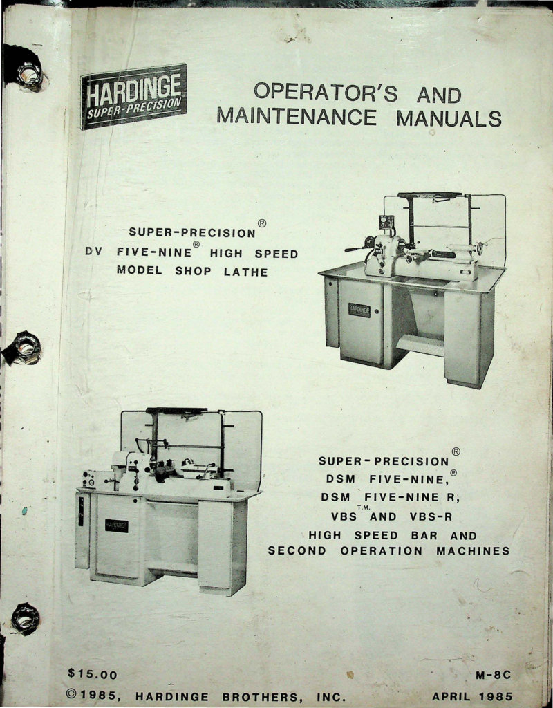
DV/DSM/VBS Lathes Operator's and Maintenance
Operator's and maintenance manual for Hardinge Super-Precision high-speed lathes covering the DV Five-Nine shop lathe model, DSM Five-Nine, DSM Five-Nine R, VBS, and VBS-R bar and second-operation machines. This workshop manual includes essential safety recommendations, detailed setup instructions, and comprehensive maintenance procedures to keep these precision lathes running reliably. Document M-8C, April 1985. Table of Contents: - CHAPTER 1 - INSTALLATION - Machine Serial Number - Foundation for Machine - Installation - Power Connection (DV/DSM Five-Nine) - System Grounding - Cleaning Machine - CHAPTER 2 - SPINDLE DRIVE (DV/DSM FIVE-NINE) - Free Spindle - Spindle Lock Pin - Starting Spindle - Change Spindle Speed - Applying and Removing Spindle Nose Tooling - Drive Lubrication - Spindle Bearing Lubrication - Drive Belt Adjustment - Drive Belt Replacement - Motor Brake - Spindle Collet Key - CHAPTER 3 - COLLET CLOSER - To Adjust Collet Closer - Collet Closer Removal - Collet Closer Replacement - CHAPTER 4 - COOLANT FACILITIES - CHAPTER 5 - TURRET - CHAPTER 6 - DOUBLE TOOL CROSS SLIDE - CHAPTER 7 - TAILSTOCK - CHAPTER 8 - COMPOUND SLIDE REST - Cleaning and Lubricating Slide Rest - CHAPTER 9 - DSM FIVE-NINE-R BAR & SECOND OPERATION MACHINE - Power Connections - Electric Countershaft Brake - Spindle Control Levers - Free Spindle - Spindle Driving Unit - Speed Changing - Spindle Belt Replacement - CHAPTER 10 - VBS SECOND OPERATION MACHINE - Changing and Adjusting Collet - Collet Closer Removal - Collet Closer Replacement
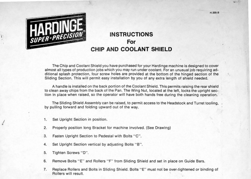
H-300-B Chip and Coolant Shield Owner's Manual
Installation and operation manual for the Hardinge H-300-B Chip and Coolant Shield, a machine tool accessory designed to contain coolant spray and metal chips during turning operations. The guide covers complete assembly procedures, from positioning the upright section and sliding shield assembly to installing the hinged section and extensions. Step-by-step instructions address bracket positioning, fastening all components securely with bolts and screws, and installing rollers on guide bars to ensure smooth shield movement. The hinged sections assemble with provided hardware and can be easily raised and folded away to grant quick access to the headstock and turret tooling without full removal. A rear handle facilitates chip removal and cleaning, while the integrated wing nut locking mechanism holds the assembly firmly in place during operation. Essential for machine shops and tool rooms setting up or maintaining the H-300-B system on turning centers and lathes.
Hardinge Bar Feed HF-6/HF-12 Parts List
Parts list for Hardinge Super-Precision pneumatic bar feed models HF-6 and HF-12. This manual includes a complete numbered component diagram identifying all 82 parts, with full part numbers, quantities required, and technical designations for each component. Coverage includes the exhaust valve assembly, check valve assembly, pneumatic fittings, and all accessories necessary for bar feed operation and maintenance. Essential reference for technicians performing service, repair, or assembly work on these precision bar feed units.
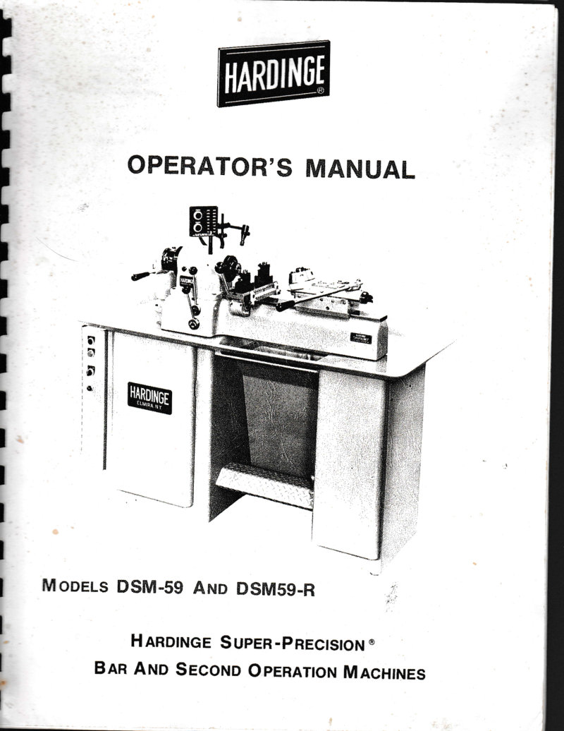
Hardinge DSM-59 DSM59-R Operator's Manual
Operator's manual for Hardinge Super-Precision Bar and Second Operation Machines, models DSM-59 and DSM59-R. This workshop manual provides safety recommendations, installation instructions, and step-by-step operating procedures for running both models. Detailed maintenance guidelines cover routine upkeep, lubrication specifications with product recommendations, spindle operation and adjustment, belt tension procedures, brake adjustment, collet operation and handling, coolant system setup, and machine leveling techniques. Includes comprehensive contents listing and technical specifications essential for daily operation and preventive maintenance.
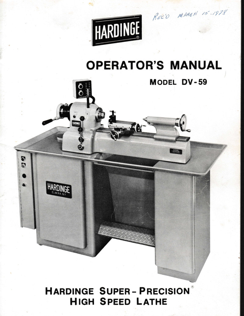
Hardinge DV-59 Operator's Manual
Operator's manual for the Hardinge DV-59 Super-Precision High Speed Lathe. This essential workshop reference covers safety recommendations, installation instructions, and comprehensive maintenance procedures. Detailed sections address belt tension adjustment and replacement, brake mechanism adjustment and insert servicing, collet closer assembly adjustment and removal, spindle operation and control, compound slide rest setup and use, tailstock configuration, coolant system operation, and optional tooling arrangements. You'll also find lubrication specifications and service schedules critical for extended machine life, floor plan guidelines for installation, and a complete contents listing. Whether performing routine maintenance or troubleshooting operational issues, this manual provides the knowledge needed to maintain and operate this precision machine tool effectively.
Hardinge DV59 Precision Lathe Parts List
Hardinge DV59 Precision Lathe and DSM59 Second Operation Machine parts list. Complete reference for identifying and ordering genuine components across the full assembly, with detailed parts diagrams covering headstock construction, collet closer mechanism, and all subassemblies. Each entry provides part number, quantity required, and technical designation. Essential documentation for technicians performing maintenance, repair, or rebuild work on these precision lathes, or for anyone sourcing replacement components.
Hardinge DV59/DSM59 Parts List
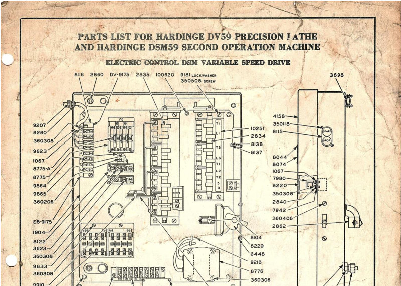
Parts list for the Hardinge DV59 Precision Lathe and Hardinge DSM59 Second Operation Machine, covering both Variable Speed Drive and 8-Speed Drive electrical control configurations. This technical reference provides detailed part identification with manufacturer part numbers, quantities, and descriptive nomenclature for all assemblies and subassemblies, including comprehensive wiring diagrams, relay components, switches, transformers, connectors, and hardware specifications essential for maintenance, repair, and assembly work on these precision machine tools.
Hardinge HLV Precision Tool Room Lathe Parts List
Comprehensive parts list for the Hardinge HLV Precision Tool Room Lathe, providing the detailed reference needed for maintenance, repair, and assembly work. Features exploded diagrams and detailed assembly drawings for critical components including the headstock and collet closer mechanism. Each component is identified by part number and quantity, making it straightforward to source replacements or plan rebuild sequences. Covers spindle sleeves, clamp nuts, spring washers, lock balls, spindle gears, splash guards, gaskets, lock pin screws, retaining rings, drive belts, front bearing nuts, wave washers, bearing retaining nuts, swivel blocks, snap rings, bearing screws, and associated fasteners. Essential for any tool room or machine shop maintaining or servicing the HLV lathe.
Hardinge HLV Tool Room Lathe Operator's Manual
Operator's instruction manual for the Hardinge Model HLV High Speed Precision Tool Room Lathe, featuring a solid hardened and ground steel dovetail bed. Published in 1954 by Hardinge Brothers, Inc. of Elmira, New York, this workshop manual covers the fundamentals of safe operation, setup, and everyday use of this compact, rigid lathe designed for precision tool and die work. Essential reference for machinists working with the HLV's spindle, chuck, and feed mechanisms.
Hardinge HLV-H Maintenance Manual
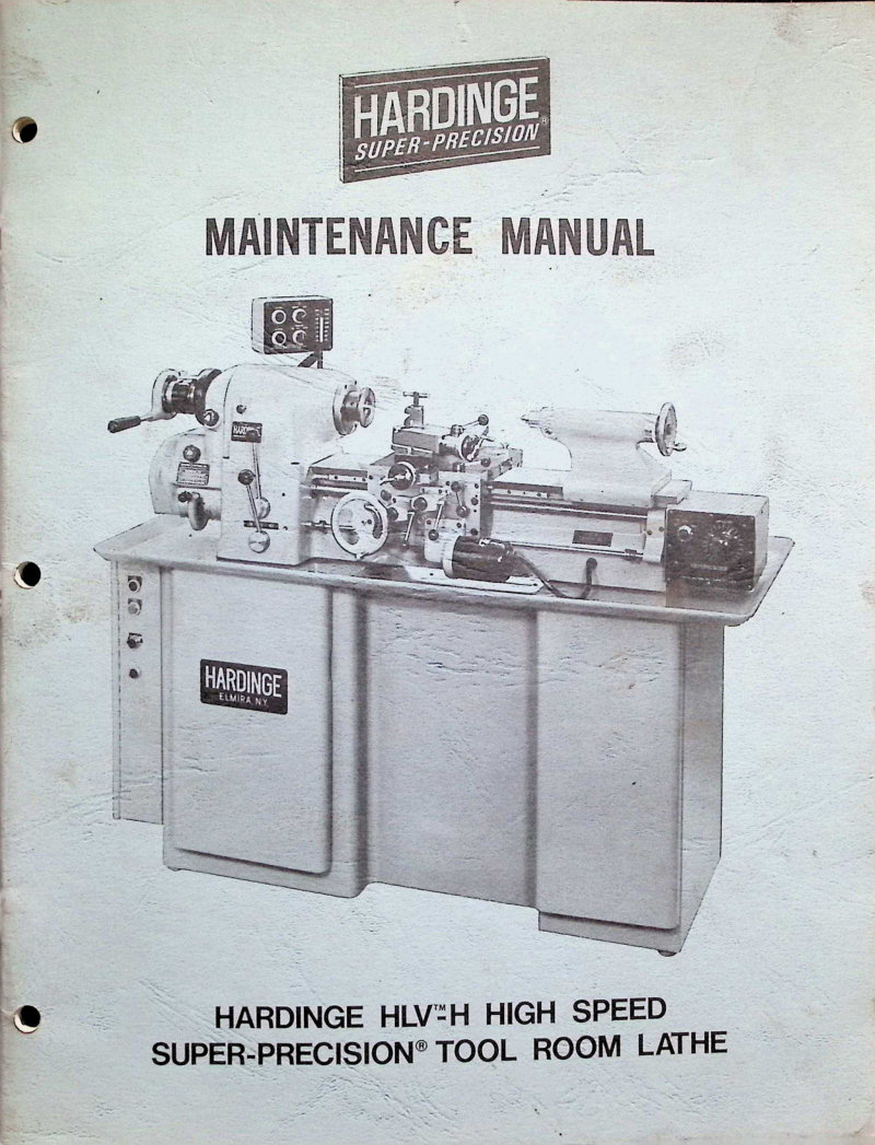
Complete maintenance manual for the Hardinge HLV-H High Speed Super-Precision tool room lathe. This 54-page workshop manual provides systematic guidance for servicing and preventive maintenance of all major systems. Covers belt adjustment and replacement procedures, brake adjustment, carriage and clutch assembly operation, gearbox disassembly and reassembly, headstock removal and reinstallation, lubrication system maintenance, spindle component care, feed screw mechanisms, tailstock assembly service, and power feed drive maintenance. Detailed safety recommendations throughout ensure proper handling of high-speed precision equipment. Essential reference for tool room technicians and maintenance personnel managing this class of precision lathe.
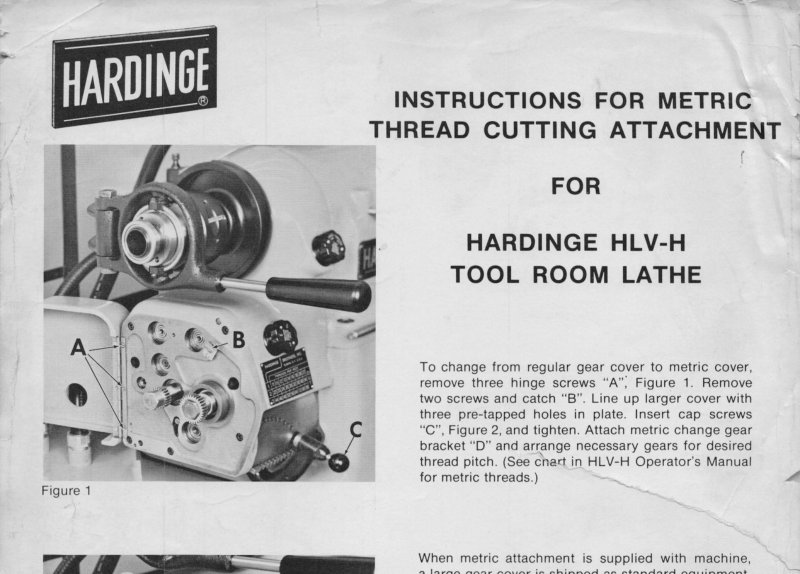
Hardinge HLV-H Metric Thread Attachment Manual
Instructions for converting the Hardinge HLV-H tool room lathe from standard gear cover to metric thread cutting configuration. Details the removal of hinge screws, installation of the large gear cover, attachment of the metric change gear bracket, and proper setup of the supplied gears—a 127-tooth gear, 50-tooth gear, and two 30-tooth gears. Also includes the procedure for using a second gear bracket to configure the lathe for English thread cutting. Single-page instruction sheet, dated May 1977.
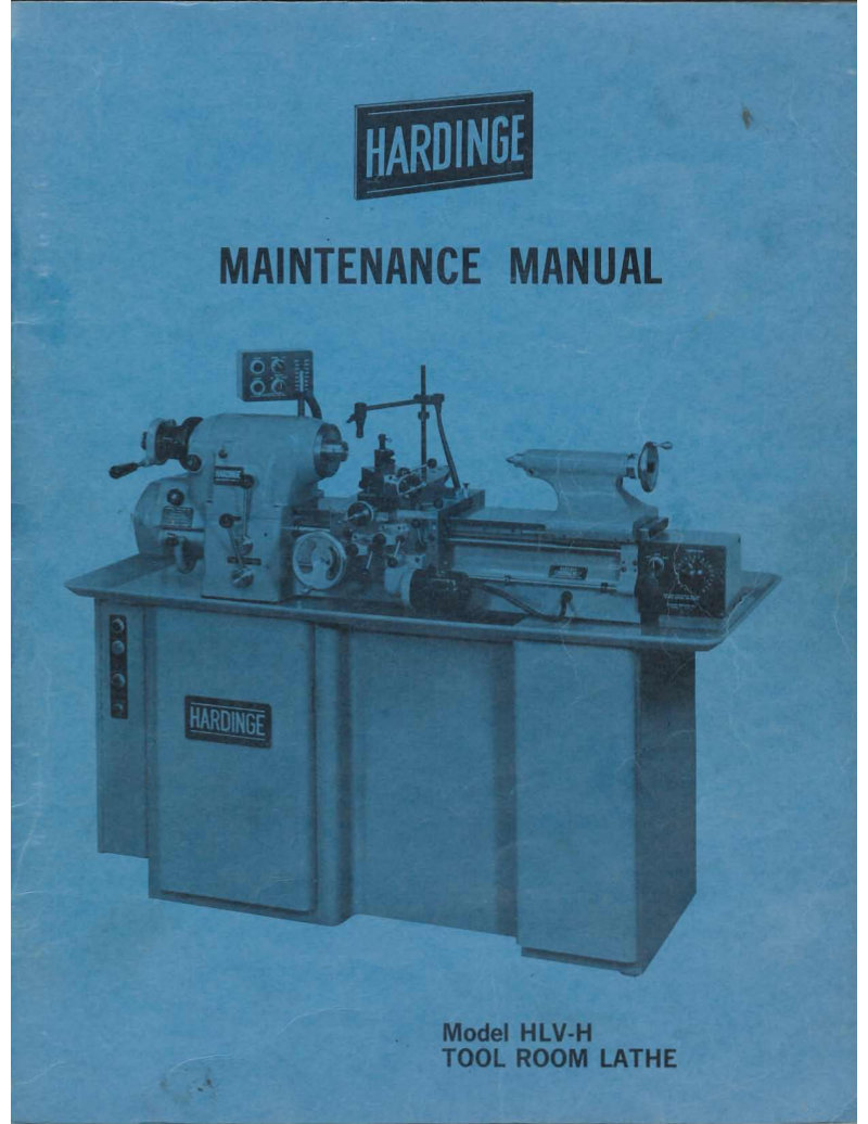
Hardinge HLV-H Tool Room Lathe Maintenance Manual
Comprehensive maintenance manual for the Hardinge HLV-H Tool Room Lathe, serving as an essential workshop reference for operators and technicians responsible for keeping this precision machine in peak operating condition. This service manual covers all preventive maintenance protocols and systematic adjustment procedures needed to maintain accuracy and reliability. Detailed instructions guide you through removal and replacement of critical components—belt drive system, collet closer mechanism, gearbox, headstock assembly, spindle, carriage, cross slide, lead screw, tailstock, and power feed drive systems—with clear step-by-step disassembly and reassembly sequences. The manual specifies exact lubrication requirements for the apron, clutches, carriage, cross slide, gearbox, and headstock bearing, ensuring proper film strength and wear protection throughout the machine. Additional sections address feed screw adjustments, electrical control functions, and troubleshooting common maintenance issues. An invaluable resource for workshop managers and skilled machinists performing routine servicing or conducting major overhauls on the HLV-H lathe.
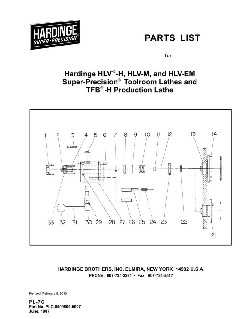
Hardinge HLV/TFB Super-Precision Parts List
Comprehensive parts list and exploded-view diagrams for Hardinge HLV-H, HLV-M, and HLV-EM Super-Precision toolroom lathes, plus the TFB-H production lathe. Numbered component illustrations paired with factory part numbers and ordering details make replacement and repair straightforward. Covers all major assemblies: collet closer mechanism, spindle drive system, tailstock, headstock, carriage assemblies, gearboxes, tool holders, and optional attachments and accessories. Essential reference for technicians, toolroom operators, and machinists maintaining these precision machines in production or job-shop environments. Table of Contents: - Adjustable Tool Block - Bed Assembly - Boring Tool Holder - Carriage & Cross Slide - View I - View II - View III - Chip & Coolant Guard - Collet Closer - Collet Closer Guard - Contour Turning Attachment - View I - View II - Coolant Facilities - Draw Spindle & Wrench - Electric Control Panel - Follower Rest - 4-Position Stop Drum - 4-Position Turret (Model L6) - Gear Boxes - Dual Dial (HLV-EM) - Single Dial (HLV-H) - Metric Converter Attachment - Headstock - Indicator Holder - Micrometer Stop - Pedestal Assembly - Power Feed Clutches - Power Feed Control Box - Power Feed Housing Assembly - Radius Turning Attachment - Rear Tool Holder - Dual Dial - Single Dial - Spindle Brake - Spindle Drive Motor Assembly - Square Turret (Model HTL) - Steady Rest - Switch Case - Tailstock - Dual Dial - Single Dial - Taper Turning Attachment - Tool Post Slide - Dual Dial - Single Dial - Variable Speed Actuator Assembly - Variable Speed Control Box - Variable Speed Pulley Assembly
Hardinge Milling Machine Operators Manual
Operators manual for the Hardinge tool room milling machine, covering all essential setup and running procedures. Details spindle speed selection via speed plate settings, operation of the high-stop-low lever and forward-stop-reverse lever for directional control, and proper adjustment of the step pulley guard and spindle lock. Explains draw spindle engagement, overarm positioning and clamping, knee gib adjustment, and saddle locking mechanisms. Includes guidance on arbor installation, overarm bracket setup, transverse feed screw lubrication points, and dial calibration for precision feed control. A practical workshop reference for operators responsible for maintaining and running this precision tool room equipment.
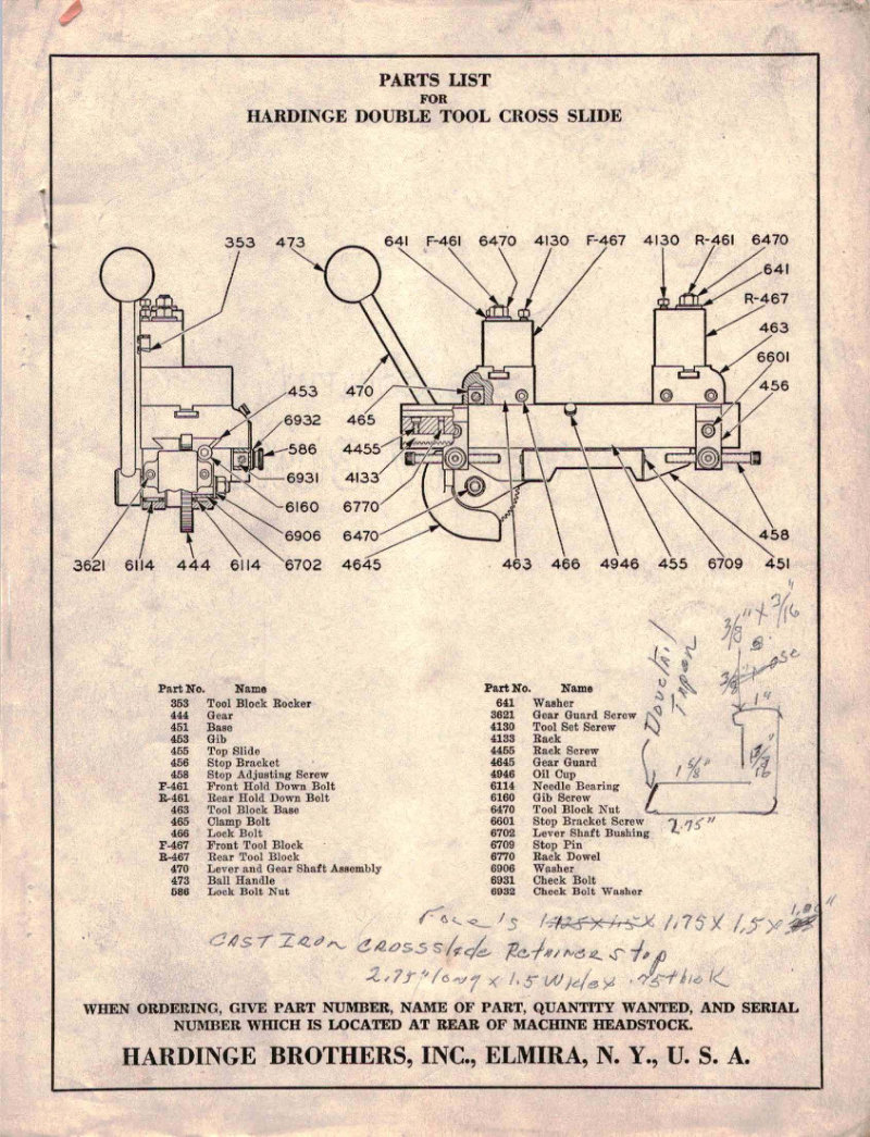
Hardinge Parts List - Cross Slide, Collet Closer, Headstock
Hardinge lathe parts list covering three essential precision-machining assemblies. The Double Tool Cross Slide (363-6982) breaks down every component—tool blocks, lead screws, gears, adjustment screws, clamp bolts, and lever mechanisms—with exploded technical drawings and part numbers for field maintenance and rebuild work. The Collet Closer section (414-8019) details the clutch fingers, tension springs, spindle shaft, and connecting linkages that control the automated chuck actuation system. The Headstock assembly (263-6989) diagrams the main frame structure, spindle bearings, draw bolt, rotating spindle, hand wheel, and belt pulley arrangement. Exact part numbers accompany each component throughout all three sections, making this an indispensable reference for ordering replacements, performing repairs, or undertaking complete restoration of Hardinge turret lathe subassemblies. The exploded views and technical drawings provide the spatial clarity needed to correctly identify parts in storage or during disassembly.
Hardinge Pneumatic Bar Feed Owner's Manual
Setup and operating instructions for the Hardinge Pneumatic Bar Feed, compatible with all Hardinge production machines. This owner's manual covers bar feed alignment procedures, pneumatic system configuration including filter-regulator and lubricator assembly, pusher cap installation for bar stock up to 7/8 inches diameter, and guide bushing specifications. Dimensional alignment data are provided for AHC, DSM-A, HC-AT, TFB-H, HLV-H, DSM-59, DV-59, HNC, and CHNC machine models, along with tube length specifications for HF-12 and HF-6 bar feed units. Essential reference for technicians setting up, maintaining, and troubleshooting pneumatic bar feed systems on Hardinge automatic machines.
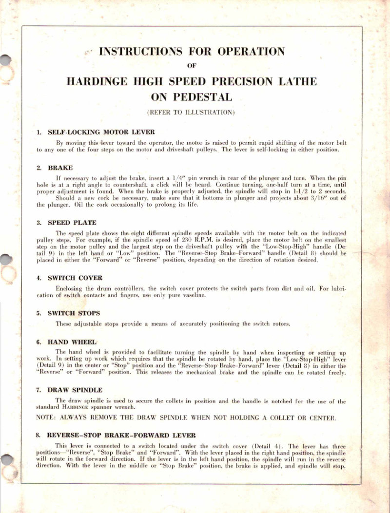
Hardinge Precision Lathe Owner's Manual
This owner's manual provides comprehensive operational guidance for the Hardinge High Speed Precision Lathe on Pedestal, a workhorse machine tool for precision turning and finishing work. The manual covers 30 essential operational details that any lathe operator needs to master for safe and efficient daily use. You'll find clear instructions on motor control — including the self-locking motor lever and brake adjustment procedures — plus detailed explanations of speed plate configuration, switch controls, and hand wheel operation. The manual walks you through critical spindle operations like draw spindle usage, proper positioning of the low-stop-high lever, and gib adjusting screws for maintaining smooth carriage travel. For tool setup and positioning, it covers the positive swivel lock, tool post configuration, and bed stop alignment. Maintenance sections address the tailstock center, oil cup upkeep, belt adjustments on both the main spindle and motor-drive systems, headstock oil cups, spindle belt adjustment, motor bearing care, and belt take-up procedures. Throughout the guide, you'll find guidance on proper positioning techniques, lubrication schedules to keep the lathe running smoothly, and essential safety procedures for both operation and routine maintenance. This is a practical workshop manual designed to help you keep your Hardinge running reliably.
Hardinge Speed Collet Chucks Parts List
Comprehensive parts list for Hardinge-Sjogren Step Chuck Type Speed Collet Chucks, an essential reference for machine shop technicians and maintenance personnel. Provides detailed part identification, pricing, and cross-references for all major assemblies including drive gears, backup plates, spindle nose components, roller and ball bearings, and fastening hardware across the full range of chuck configurations. Use this parts list when ordering replacement components, planning preventive maintenance schedules, or diagnosing wear issues on your collet chuck equipment.
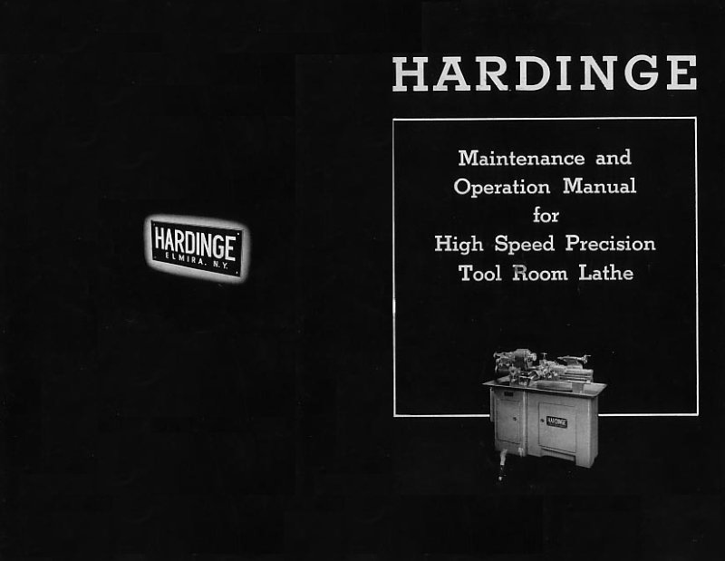
Hardinge TL Lathe Maintenance and Operation Manual
Maintenance and operation manual for the Hardinge TL high-speed precision tool room lathe. This workshop manual provides comprehensive coverage of the machine's control systems and mechanical components, including the electric motor control lever, carriage lever, handwheel, speed-change handles for both three and ten-position gear selections, spindle drive gear, draw spindle handle, change gear cover, spindle reverse lever, and main control panel cover. Detailed operational instructions walk you through the function and proper use of every major control and component on the machine. An essential workshop reference for operators and technicians performing routine maintenance or troubleshooting adjustments on this classic precision lathe.
HC Chucking Machine Maintenance Manual
Maintenance manual for the Hardinge Model HC chucking machine. This workshop manual provides comprehensive preventive maintenance procedures, adjustment techniques, and step-by-step repair instructions for sustained operation and troubleshooting. Detailed coverage includes belt maintenance and replacement, brake spindle servicing, carriage clutch and gearbox overhaul, drive system repair, feed screw adjustment, pulley alignment and replacement, speed change mechanism operation, turret and cross slide assembly, headstock maintenance, and electrical system diagnostics. An essential reference for machine operators and maintenance technicians managing this precision industrial lathe.
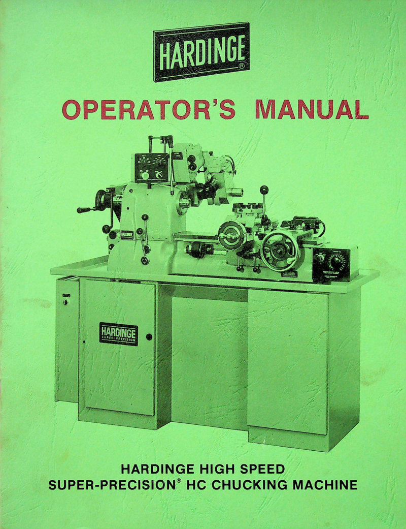
HC Super-Precision Chucking Machine Operator's Manual
Operator's manual for the Hardinge HC Super-Precision chucking machine, a high-speed production lathe built for precision manufacturing. The manual covers essential safety recommendations and step-by-step installation procedures, including machine leveling and electrical connections needed to bring the equipment into full operation. You'll find detailed lubrication schedules for the spindle, carriage, clutch assembly, gearbox, and vertical feed screw—critical for maintaining spindle performance and extending equipment life. Operating procedures are explained clearly for spindle control, brake adjustment, collet closer tuning, power feed clutches, and carriage handwheel operation including dial settings and stop drum adjustment. The guide addresses cross-slide stops, reference scale calibration, and turret indexing and operation. Complete machine specifications are included for reference. A companion HC Chucking Machine Maintenance Manual covers the preventive maintenance schedule in greater detail.
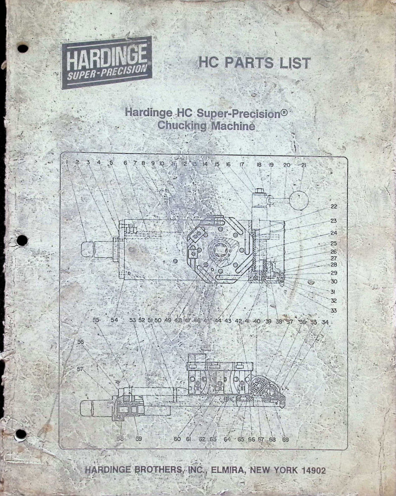
HC Super-Precision Chucking Machine Parts List
Parts list and assembly reference for the Hardinge HC Super-Precision Chucking Machine, featuring numbered exploded-view diagrams and detailed component identification across all major systems. Covers air-lube regulators, bed assembly, carriage, gear train, clutch assembly, collet closer, coolant system, headstock, pedestal, power case, spindle brake, spindle motor mounting, threading head automatic chasing assemblies, turret, variable speed control, and vertical cut-off slide. Includes parts ordering information and Hardinge Brothers, Inc. contact details for sourcing replacements and technical support.
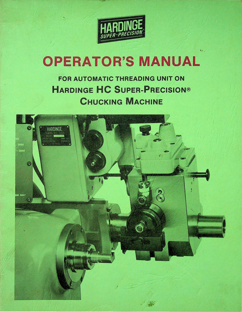
HC Super-Precision Threading Unit Operator's Manual
Operator's manual for the HC Super-Precision threading unit, the automatic threading attachment for Hardinge HC Super-Precision chucking machines. This workshop manual provides detailed instructions for setting up and executing threading operations, including lead screw selection, follower adjustment, and positioning of threading tool holders. Coverage includes thread depth control and fine adjustment procedures, metric and English thread reference charts, spindle speed tables, and pipe thread specifications. The manual also outlines maintenance schedules, lubrication points, and safety protocols essential for reliable operation of the threading unit, along with a reference guide for available lead screws and compatible threading tools.
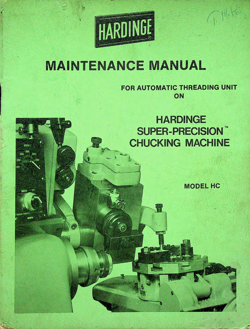
HC Threading Unit Maintenance Manual
Maintenance manual for the automatic threading unit fitted to Hardinge Super-Precision Model HC chucking machines. Provides comprehensive guidance on disassembly and reassembly of the chasing head, cylinder housing, tool post, and knockout control mechanism, along with all associated components. Details air and electrical connection requirements, proper lubrication procedures, preventive maintenance schedules, and step-by-step adjustment techniques for feed rate and slide travel. An essential workshop reference for anyone servicing these precision threading units.
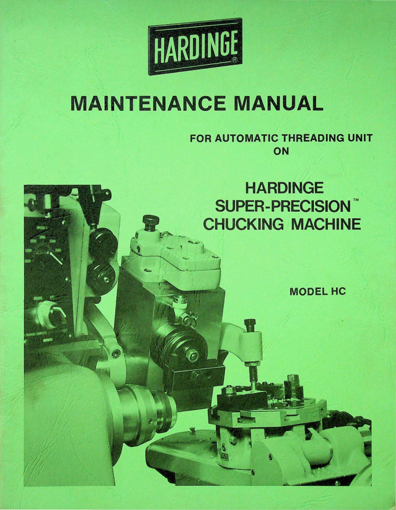
HC Threading Unit Maintenance Manual
Maintenance manual for the Hardinge HC Super-Precision automatic threading unit—the specialized attachment that handles threadchasing on the HC chucking machine. This workshop manual covers everything you'll need to service and repair the unit: air and electrical connections, tool post disassembly procedures, cylinder housing and chasing head removal and reinstallation, feed rate and slide travel adjustment screw removal and replacement, cycle stop micro switch replacement, knockout control disassembly and reassembly, proper gib adjustment for tight tolerances, lubrication points and schedules, and mounting bracket assembly. Includes step-by-step procedures for each major subsystem. Assumes you have foundational knowledge of machine tool maintenance.
HC Threading Units Operator's Manual
Operator's manual for the automatic and manual threading units fitted to Hardinge Model HC super-precision chucking machines. This workshop manual provides detailed front and rear view photographs of the automatic threading unit, along with essential guidance for operating both threading configurations on these precision production lathes. Essential reference for machine operators and maintenance staff working with HC-series equipment. Published by Hardinge Brothers, Inc., Elmira, New York.
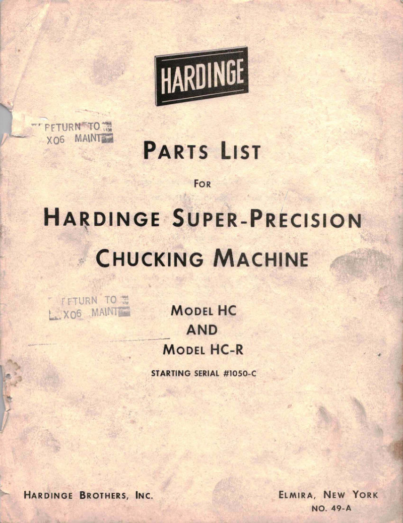
HC/HC-R Super-Precision Chucking Machine Parts List
Complete parts list for Hardinge HC and HC-R Super-Precision Chucking Machine models, starting from serial #1050-C. This workshop manual is the authoritative parts reference for technicians and machine operators, covering all major assemblies: automatic chasing head (views I and II), automatic turret assembly, bed assembly, brake assembly, carriage assembly, chasing knockout control, clutch assembly, collet closer, electric control panel, headstock assembly, pedestal assembly, power feed controls, tool post assembly, variable speed controls, and vertical cut-off attachment. Use it to identify correct replacement parts, troubleshoot component issues, and understand machine configuration. Published by Hardinge Brothers Inc., Elmira, New York, document No. 49-A. Table of Contents: - Automatic Chasing Head - View I - Automatic Chasing Head - View II - Automatic Turret Assembly - Bed Assembly - Brake Assembly - Carriage Assembly - View I - Carriage Assembly - View II - Carriage Gear - Chasing Head (Manual) - Chasing Knockout Control - View I - Chasing Knockout Control - View II - Chasing Knockout (Manual) - Clutch Assembly - Collet Closer - Coolant Facilities - Electric Control Panel - Headstock Assembly - Pedestal Assembly - Power Feed Control - Power Feed Assembly - Production Threading Arm - Tool Post Assembly - Variable Speed Control Box - Variable Speed Drive Control - Variable Speed Pulley - Vertical Cut-Off Attachment - Drive Assembly - Electric Control Panel - Headstock Assembly - Pedestal Assembly
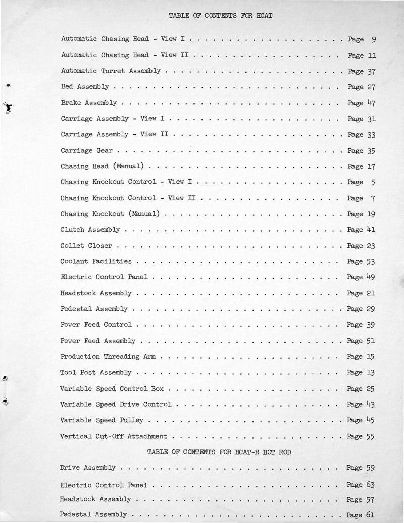
HCAT Chasing Knockout Control Parts List
Complete parts list and technical diagrams for Hardinge HCAT and HCAT-R chasing knockout control systems. This reference provides detailed component identification, original part numbers, and exploded assembly views for maintaining and servicing automatic chasing heads, turret assemblies, carriage assemblies, clutch systems, and related mechanical components. Essential workshop documentation for technicians working on Hardinge automatic chucking equipment. Table of Contents: - Automatic Chasing Head - View I - Automatic Chasing Head - View II - Automatic Turret Assembly - Bed Assembly - Brake Assembly - Carriage Assembly - View I - Carriage Assembly - View II - Carriage Gear - Chasing Head (Manual) - Chasing Knockout Control - View I - Chasing Knockout Control - View II - Chasing Knockout (Manual) - Clutch Assembly - Collet Closer - Coolant Facilities - Electric Control Panel - Headstock Assembly - Pedestal Assembly - Power Feed Control - Power Feed Assembly - Production Threading Arm - Tool Post Assembly - Variable Speed Control Box - Variable Speed Drive Control - Variable Speed Pulley - Vertical Cut-Off Attachment - Drive Assembly - Headstock Assembly - Pedestal Assembly
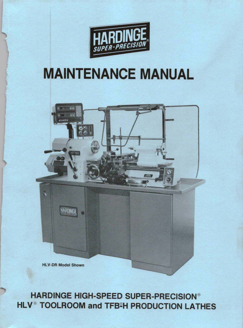
HLV and TFB-H Production Lathe Maintenance Manual
Comprehensive maintenance manual for Hardinge HLV High-Speed Super-Precision Toolroom and TFB-H Production Lathes, covering serial number 13585 and higher. This workshop manual outlines essential maintenance procedures, preventive care schedules, and operational best practices for optimal machine performance and longevity. Published February 1991, Manual M-10C (Part number M C-0009500-0010). Includes critical safety recommendations, OSHA hazard communication requirements, and specifications for petroleum-based cutting fluids. An indispensable reference for technicians, operators, and maintenance staff responsible for these precision lathe systems. Table of Contents: - CHAPTER 1 - CARRIAGE - Carriage Apron Disassembly - Carriage Apron Reassembly - Clutch Adjustment - Carriage Lock - Removal - Replacement - Gear Rack - Removal - Replacement - Lubrication - Gib Adjustment - Handwheel - Removal - Disassembly - Reassembly - Replacement - Clearance Adjustment - Lead Screw (HLV® Machines only) - Removal - Replacement - Lubrication - Lead Screw Nut (HLV Machines only) - Removal - Replacement - Lubrication - Carriage Lubrication System - Replacing an Oil Feed Tube Metering Unit - Operating the Lubricator - Filling the Lubricator Reservoir
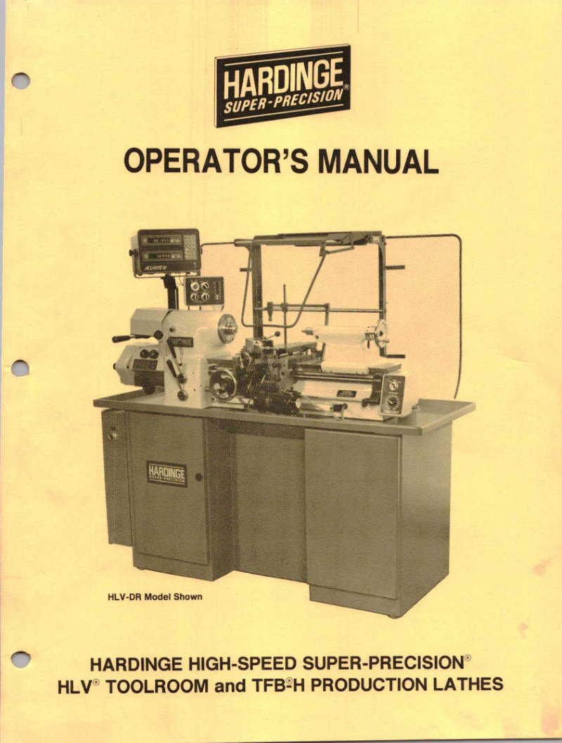
HLV and TFB-H Production Lathes Operator's Manual
Operator's manual for the Hardinge HLV toolroom lathe and TFB-H production lathe series. This workshop manual covers essential setup including machine installation, foundation requirements, leveling, and electrical connections. It details spindle operation, brake function, speed changing, tailstock adjustment, collet closer mechanisms, carriage and compound slide control, and power feed operation. The manual includes complete lubrication schedules, thread cutting techniques, tooling application guidance, and routine maintenance procedures. It also provides safety recommendations, full machine specifications, comprehensive thread charts, and precise tooling dimensions. 30 pages with technical diagrams and step-by-step operational instructions.
HLV TFB-H Toolroom Lathe Service Manual
Comprehensive service manual for the Hardinge HLV and TFB-H toolroom lathes, covering the full range of maintenance and repair procedures essential for keeping these high-speed super-precision machines in optimal working condition. The manual details disassembly and reassembly sequences for the headstock, gearbox, carriage, apron, collet closer, brake assembly, feed mechanisms, tailstock, and tool post slide. Step-by-step lubrication protocols and adjustment procedures are provided for each major component, along with detailed preventive maintenance guidelines to extend machine life and ensure reliable performance. Technical specifications cover bearing types, lubricant grades, and compatibility requirements. Safety recommendations are integrated throughout, with particular attention to high-speed operation hazards and proper lockout procedures during servicing. 55 pages with complete table of contents. Table of Contents: - Bed Lever—Removal - Replacement - Belt—Adjustment, Replacement - Brake—Adjustment - Insert Replacement - Solenoid and Spring Replacement - Carriage—Apron Disassembly - Apron Reassembly - Clutch Adjustment - Gear Rack Removal - Handwheel Disassembly - Lock Removal - Lubrication System - Collet Closer—Removal, Replacement - Coolant Facilities - Cross Slide—Removal - Feed Screw Nut Backlash Adjustment - Feed Screw, Disassembly - Feed Screw, Assembly - Drive Feed Screw Nut—Removal - Replacement - Electrical, Connections - Control Functions - Power Feed Control Panel - Gear Box—Removal - Disassembly - Assembly and Replacement - Gib Adjustments - Headstock—Removal - Replacement - Installation Instructions - Lead Screw—Removal - Lead Screw Nut—Removal - Replacement - Lubricants and Sealer - Lubrication—Apron and Clutches - Carriage - Cross Slide - Drive - Gearbox - Headstock Bearing - Tool Post Slide - Power Feed Drive—Removal, Disassembly - Preventive Maintenance - Speed Change Mechanism—Removal, Disassembly - Assembly and Replacement - Serial Number - Spindle Collet Key - Spindle—Lock Pin - Limit Switch Replacement - Tailstock—Disassembly - Assembly - Alignment - Tool Post Slide—Disassembly - Assembly - Feed Screw Nut Adjustment - Variable Speed Pulley and Countershaft—Removal
HLV-H Super-Precision Tool Room Lathe Parts List
Complete parts list and reference manual for the Hardinge HLV-H Super-Precision Tool Room Lathe, applicable to machines with serial numbers beginning at 100. This comprehensive workshop manual covers all major assemblies and subassemblies essential for maintenance, repair, and parts ordering: headstock spindle system, tailstock, machine bed, carriage saddle, four-station and square turrets, gearbox units, clutch and brake mechanisms, automatic power feed, variable-speed transmission systems, tool post configurations, taper attachment, collet closer assembly, and coolant circulation facilities. The document provides systematic guidance on identifying and ordering genuine Hardinge replacement parts, making it an indispensable service manual for tool room operators and maintenance technicians working with this precision lathe. Table of Contents: - Bed Assembly - Brake Assembly - Carriage Apron Assembly - Carriage and Cross Slide Assembly - Carriage Half Nut Assembly - Clutch Assembly - Collet Closer Assembly - Coolant Facilities - Contour Tracing Assembly View I - Contour Tracing Assembly View II - Electric Control Panel - Four Station Turret - Gear Assembly - Gear Box Units Change Gear Bucket - Gear Box Units Cluster Shaft and Change Shaft - Gear Box Units Clutch Shaft and Intermediate Shaft - Gear Box Units Gear Box - Gear Box Units Idler Shaft and Reverse Shaft - Gear Box Units Tumbler and Shaft - Headstock Assembly - Micrometer Stop - Pedestal Base Assembly - Power Feed Control Box - Power Feed Assembly - Radius Turning Attachment - Rear Tool Holder Slide Assembly - Square Turret Assembly - Tailstock Assembly - Taper Attachment - Tool Post Assembly - Variable Speed Actuator Assembly - Variable Speed Control Box Assembly - Variable Speed Pulley Assembly
HLV-H Toolroom Lathe Parts List
Comprehensive parts list for the Hardinge HLV-H toolroom lathe covering serial numbers 100 to 4999, dated September 1987. This workshop manual reference includes 27 detailed assembly sections organized by functional component: bed, brake system, carriage, clutch, collet closer mechanism, coolant system, contour tracing attachment, electrical control panel, four-station turret, gear assemblies, headstock, micrometer stop, pedestal base, power feed drive, radius turning attachment, rear tool holder slide, square turret, tailstock, taper attachment, tool post, and variable speed components. Practical guidance on ordering replacement parts included to support maintenance and repair operations. Table of Contents: - Bed Assembly - Brake Assembly - Carriage Apron Assembly - Carriage and Cross Slide Assembly - Carriage Half Nut Assembly - Clutch Assembly - Collet Closer Assembly - Coolant Facilities - Contour Tracing Assembly - View I - View II - Electric Control Panel - Four Station Turret - Gear Assembly - Gear Box Units - Change Gear Bucket - Cluster Shaft and Change Shaft - Clutch Shaft and Intermediate Shaft - Gear Box - Gear Box Idler Shaft and Reverse Shaft - Gear Box Tumbler and Shaft - Headstock Assembly - Micrometer Stop - Pedestal Base Assembly - Power Feed Control Box - Power Feed Assembly - Radius Turning Attachment - Rear Tool Holder Slide Assembly - Square Turret Assembly - Tailstock Assembly - Taper Attachment - Tool Post Assembly - Variable Speed Actuator Assembly - Variable Speed Control Box Assembly - Variable Speed Pulley Assembly
Lever Type Speed Collet Chucks Parts List
Complete parts list for Hardinge-Sjogren lever type speed collet chucks, covering both threaded spindle nose and taper key drive spindle nose configurations. The document opens with a detailed exploded view diagram on page 1 that identifies every numbered component and shows assembly relationships. Page 3 provides a comprehensive pricing table for 20 essential parts, including clutch rings, retaining nuts, breather balls, compression springs, and fasteners—each with its corresponding part number for accurate ordering and replacement. This parts list serves as the reference manual for technicians and operators maintaining or rebuilding these precision chuck assemblies.
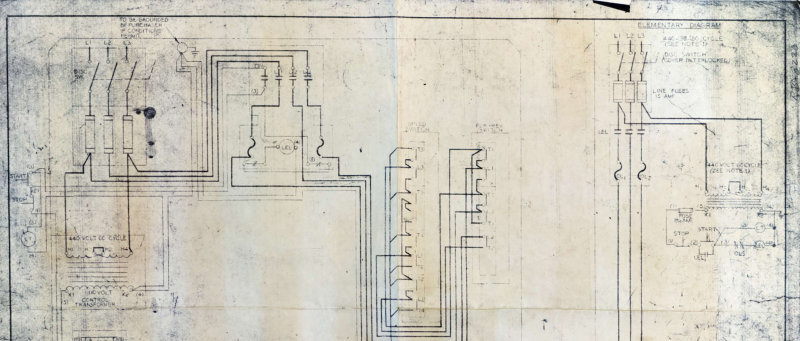
RB-8220 Wiring Schematic
Electrical wiring schematic for the Hardinge RB-8220 precision machine. This single-page technical diagram maps the complete circuit architecture, detailing transformers, motor control contactors, switching circuits, and terminal connections. Includes a comprehensive component legend for rapid identification of each electrical element. Essential for troubleshooting, maintenance, and understanding the machine's control system.
Spindle Bar Feed HF-1 Installation Manual
Installation and operation manual for the Hardinge Model HF-1 Spindle Bar Feed system. Provides setup procedures and configuration guidance for integrating with Hardinge production machines including the DSM-59, VBS, ASM-5C, DSM-A, HC, AHC, TFB-H, HSL-59, DV-59, and HLV-H models. Features detailed spacer configuration diagrams tailored to each machine type, systematic piston-liner selection charts for bar stock diameters ranging from 1/32 inch through 3/4 inch, and pressure adjustment specifications from 0 to 60 pounds. Accommodates bar lengths up to 24 inches, making it suitable for a wide range of production setups and bar-fed machining applications.
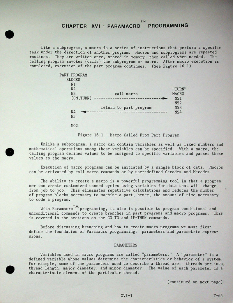
Superslant AB Programming Manual Part 4
Part 4 of the Hardinge Superslant AB Programming Manual covers Paramacro programming in depth. This section provides detailed reference material for system, local, letter, PAL, and PAL flag parameters, plus stored constants and programmed word indicators. You'll find complete parameter tables for quick lookup, parameter assignment commands including Assign Parameter and Call Macro functions, conditional logic with If-Then structures, and G-Code and M-Code block integration. The manual also walks through macro programming fundamentals, showing how to work with variables and mathematical operations to create efficient, reusable code for CNC machining workflows.
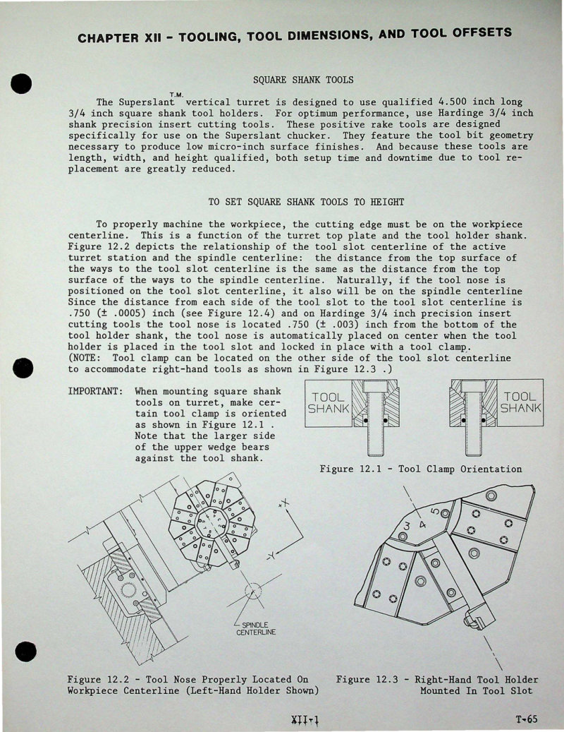
Superslant AB Technical Data and Parts List
Hardinge Superslant AB technical reference covering Chapter XII tooling specifications and parts configuration. Details square shank tool geometry (3/4 inch shank, 4.500 inches overall length), tool holder assembly dimensions, and qualified tool holder specifications for the vertical turret. Provides precise X and Z tool dimension references essential for accurate offset setup and tool positioning. Technical drawings illustrate vertical turret top plate layout, tool clamp orientation relative to turret stations, and tool nose positioning geometry. Qualified tool holder dimensioning includes tight tolerances (±.003 inch) with clear definitions of X Tool Dimension, Z Tool Dimension, and Tool Nose Reference Point measurement methods. Dimensional diagrams specify tool slot centerline locations, tool nose radius compensation values, and distinction between O.N.R. (Over Nose Radius) and T.S.C. (To Sharp Corner) measurement protocols — critical for setting up cutting tool offsets correctly on CNC and manual Superslant machines. Essential reference for tool room personnel, setup technicians, and machine operators responsible for tool preparation and offset data entry. Table of Contents: - # Table of Contents - X AND Z TOOL DIMENSIONS
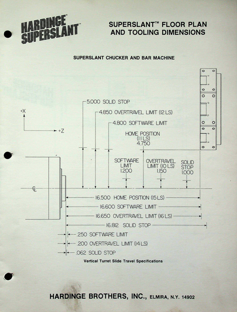
Superslant Floor Plan and Tooling Dimensions
Technical documentation for the Hardinge Superslant Chucker and Bar Machine covering floor plan layout and tooling dimensions. This manual provides detailed vertical turret slide travel specifications with exact measurements for home position coordinates, software limits, overtravel limits, and solid mechanical stops across both horizontal and vertical axes. Includes floor plan views that illustrate machine spatial configuration and overall footprint dimensions — essential reference material for machine installation, setup, and workshop layout planning. Table of Contents: - Air Control Valve Assembly - Axis Drive Covers - Carriage and Cross Slide - View I - View II - Carriage Drive - Chip and Coolant Guard - Collet Closer - Collet Closer Subassembly - Control Case (Allen-Bradley) - Control Case and Power Case Mounting Arrangement - Allen-Bradley - General Numeric - Control Console - Allen-Bradley End Views - Allen-Bradley Front View - General Numeric End Views - General Numeric Front View - Coolant Facilities - Coolant Tank and Pump Assembly - Headstock - Head Wall Assembly - Heat Exchanger - Hose and Fitting Diagrams - Hydraulic - Lubrication - Pneumatic - Hydraulic Control Panel - With Tailstock - Without Tailstock - Hydraulic Control Valve Assembly - Hydraulic Power Unit - Lubricator - Part Catcher - Pedestal - End Views - Front View - Power Case - Allen-Bradley Components - General Numeric Components - Hardware - Spindle Cartridge - Spindle Drive Motor - Spindle Feedback Assembly - Allen-Bradley - General Numeric - Tailstock - Tailstock Drive - Tailstock Manifold - Turret Assemblies - End-Working Turret and Turret/Tailstock Support - Turret View I - Turret View II - Turret View III - Valve Compartment - Valve Compartment Junction Box
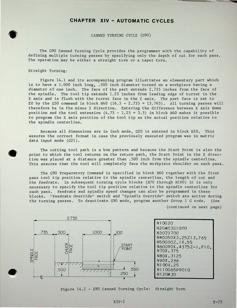
Superslant GN Programmers and Operators Manual
Part 3 of the Hardinge Superslant GN Programmers and Operators Manual covers automatic machining cycles for CNC lathe operation. Chapter XIV provides comprehensive coverage of the G90 Canned Turning Cycle for straight and taper turning, along with the G71 and G70 Multiple Repetitive Rough and Finish Turning cycles—essential routines for production work. The manual includes detailed technical specifications, CNC programming parameters, dimensioned engineering drawings, and real-world program examples to guide setup and execution on the Superslant GN platform. Table of Contents: - SET PARAMETER PROCEDURE
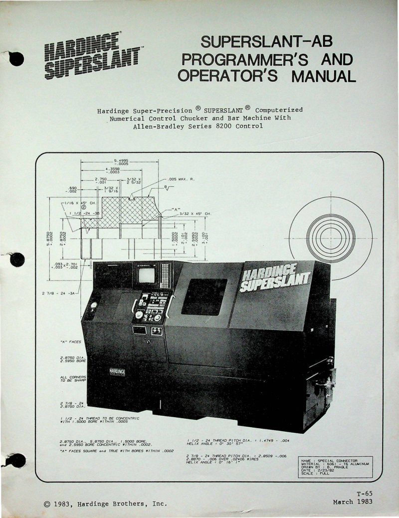
Superslant-AB Programmer's and Operator's Manual
Programmer's and operator's manual for the Hardinge Superslant computerized numerical control bar machine, featuring the Allen-Bradley Series 8200 control system. This comprehensive workshop manual covers setup, operation, and programming procedures for two-axis machines, two-axis configurations with tailstock, and three-axis models. Includes detailed technical drawings, machine specifications, tool offsets, cycle timing, and step-by-step operational procedures essential for initial setup and daily production. Provides the control logic and parameter reference needed to program complex parts efficiently on this precision bar-turning system. Document dated March 1983, a valuable reference for shops maintaining or operating Hardinge Superslant CNC equipment from this era. Table of Contents: - CHAPTER I - INSTALLATION - Machine Serial Number - CNC Control Serial Number - Foundation for Machine - Installation - Air Connection - Power Connection - Earth Ground - System Grounding - Cleaning Machine - CHAPTER II - SYSTEM 8200 SOFTWARE, POWER-UP, AND POWER-DOWN PROCEDURES - Processor - Interface - Power Supply - Bubble Memory - System Software - Software Loading Procedure - Power-Up Procedure - Power-Down Procedure - P2 Processor Restart Procedure - CHAPTER III - MAINTENANCE OF LUBRICATION, COOLANT, AND HYDRAULIC SYSTEMS, AND AIR FILTERS - Lubrication - Coolant Facilities - Chip Removal - Hydraulic Power Unit - To Bleed Hydraulic Lines - To Adjust Spindle Brake - Heat Exchangers - Control Case Air Conditioning Unit - To Clean Air Filters - To Replace Hydraulic Sensor Filter - CHAPTER IV - COLLET CLOSER - Spindle Lock Pin - Free Spindle - Hydraulic Collet Closer - To Adjust Hydraulic Collet Closer - To Clean Collet Closer - CHAPTER V - TAILSTOCK - Tailstock Operation - Manual - Programmed
Superslant-AB Programming Manual
Part 2 of the Superslant-AB operator and programmer manual covering Part Program Language essentials for CNC machining. Details decimal point programming conventions, axis designation standards, and tape coding in both EIA and ASCII formats. Explains tape parity check mechanisms for data integrity, End of Block character definitions, Rewind Stop character functionality, and the proper structure of Part Program Blocks with recommended sequence for organizing data block elements. Essential reference for anyone programming parts on Hardinge Superslant-AB turning centers. Table of Contents: - E-WORD - Velocity/Distance Feedrate Coding (H93) - Per Minute Feedrate Coding (H94)
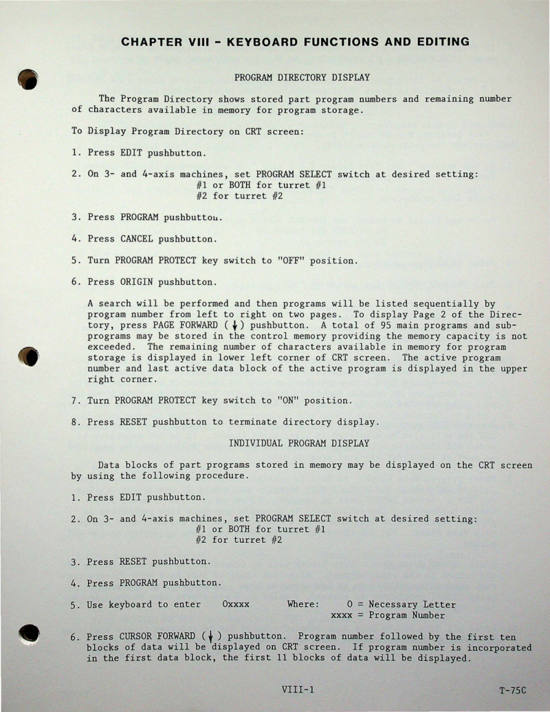
Superslant-GN Keyboard Functions Technical Manual
This chapter from the Superslant-GN control system technical manual covers keyboard functions and editing procedures essential for CNC machine operation. You'll learn to navigate the Program Directory Display to review stored programs at a glance, access Individual Program Display for detailed program inspection, and execute Program Storage from the keyboard to save new machine code. The manual walks through Program Cancellation methods when revisions are needed and provides comprehensive Memory Management techniques to optimize available storage capacity. Step-by-step instructions guide you through displaying and retrieving stored programs, entering program data blocks efficiently, monitoring and managing memory usage, and using keyswitch-protected controls to safeguard critical programs from accidental modification. Ideal for operators and technicians working with Superslant-GN control systems who need authoritative guidance on keyboard operation and data management.
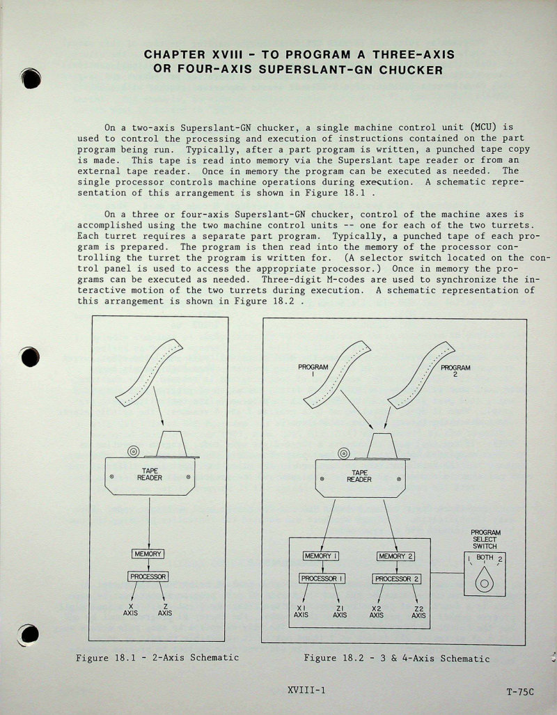
Superslant-GN Programmer Manual: 3/4-Axis
Superslant-GN Programmer Manual covering three-axis and four-axis operation. This manual details essential programming procedures for the Superslant-GN chucking system, including synchronization codes using 3-digit M-code formats, program numbering conventions, and program select switch operation. It covers spindle command syntax, turret #2 command restrictions, and control configuration schematics for both 2-axis and 3/4-axis setups to guide proper machine configuration and CNC programming workflows. Table of Contents: - SYNCHRONIZATION CODES (3-DIGIT M-CODES) - PROGRAM NUMBER

Superslant-GN Programmer's and Operator's Manual
Programmer's and operator's manual for the Hardinge Super-Precision Superslant, a computerized numerical control chucker and bar machine equipped with the General Numeric System GN6T control. This workshop manual addresses 2-axis, 3-axis, and 4-axis configurations and serves both programmers and machine operators. The document details programming procedures using radius programming (with diameter programming offered as an option), provides a comprehensive G-code reference covering Japanese standard codes and their EIA equivalents, and walks through operating instructions for day-to-day machine control. Originally published June 1983, this service manual remains essential for anyone setting up, programming, or running this precision turning center. The manual bridges programming theory and practical operation, making it suitable for CNC setup technicians and shop floor personnel alike.
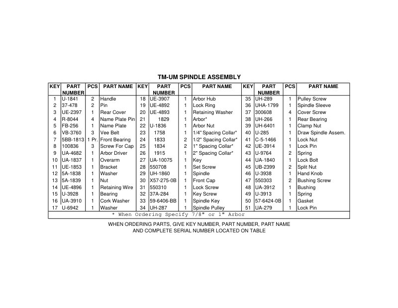
TM-UM Milling Machine Parts List
Parts list and assembly diagrams for the HARDINGE TM-UM Tool Room Milling Machine, providing complete reference documentation for component identification and ordering. The spindle assembly section details 51 numbered parts including handles, pins, bearings, arbor components, pulleys, and gaskets with precise technical drawings. The column assembly covers 35 numbered parts encompassing yokes, levers, shafts, controls, and oil pan components. Each technical drawing features callout key numbers matched to corresponding part numbers, piece quantities, and part designations. Ordering instructions specify the required information—key number, part number, part name, and complete serial number—making this an essential reference for maintenance, repair, and parts procurement for the TM-UM milling machine.
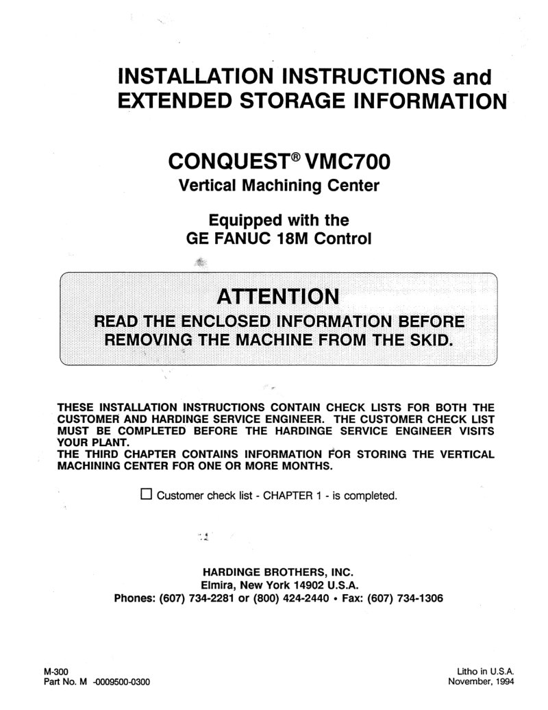
VMC700 Installation Instructions Manual
Installation and extended storage manual for the Hardinge CONQUEST VMC700 vertical machining center with GE FANUC 18M control. This workshop manual covers every step of bringing the machine online: customer installation checklist, foundation and floor placement requirements, machine cleaning and alignment, electrical grounding (earth and system), power connections, pneumatic air setup, lubrication oil specification and fill, cutting fluid coolant charging, and long-term storage preparation. Separate checklists are provided for customer personnel and Hardinge service engineers to track completion of critical tasks. Machine specifications include approximately 11,500 lbs shipping weight and foundation concrete minimum of 3000 psi. Precision level tolerances are specified at 0.0003 inches per foot. The storage section details full preservation procedures for machines awaiting installation or being stored offline, including re-commissioning steps to bring the VMC700 back into service. Essential reference for shop floor setup and maintenance planning.