EPSON - Service Manuals
26 manuals available for download
EPSON is a globally recognized manufacturer of imaging and printing technology, with a comprehensive range of professional and consumer-grade scanners and photo printers. Our extensive documentation library includes detailed service manuals, repair guides, and technical specifications to support technicians, service centers, and users in maintaining and troubleshooting EPSON equipment. Whether you need a workshop manual for routine maintenance, a parts list for component replacement, or a comprehensive owner's manual with troubleshooting guidance, our PDF downloads provide the essential technical information required for professional-level device support and repair operations.
EPSON - Epson Perfection 1200u Service
Comprehensive service manual for the Epson Perfection 1200u scanner, designed for maintenance technicians and professional repair providers. This 94-page workshop manual delivers the technical depth needed to maintain, diagnose, and repair this precision scanning device. Covers complete disassembly and reassembly procedures, detailed technical specifications, calibration protocols, and practical troubleshooting guidance for common failures. Internal functional diagrams and component schematics enable you to understand exactly how each subsystem operates, while step-by-step procedures walk through resolution of typical scanning faults. Whether you're performing preventive maintenance or tracking down a specific malfunction, this repair manual provides the internal architecture knowledge and systematic diagnostic approach to identify root causes quickly and execute repairs with confidence.
EPSON - Epson Perfection 1250photo Service
Comprehensive service manual for the EPSON Perfection 1250 and 1250 PHOTO color flatbed scanners. This detailed workshop reference covers all essential maintenance, troubleshooting, and repair procedures for these high-resolution scanning devices. Organized into six primary chapters, the manual begins with product features and control panel operations, then progresses through a technical overview of carriage assembly and control circuit functionality. The troubleshooting section systematically identifies error conditions and provides practical remedies. Dedicated chapters guide you through step-by-step disassembly and reassembly of all major components, followed by maintenance protocols for document glass and carriage lubrication. The comprehensive appendix supplies precise electrical and optical specifications, operating environment requirements, USB interface details, and control codes. Connector diagrams with complete pin assignments clarify all interface points. Full circuit schematics for both main interface and CCD boards enable in-depth diagnostics. A detailed parts list with part numbers supports component identification and ordering. Exploded diagrams show how subassemblies fit together, aiding reassembly accuracy. This repair manual incorporates critical safety precautions and electrostatic discharge warnings throughout. Designed for EPSON-certified service technicians and professional repair facilities, it provides the technical foundation necessary for successful restoration of these sophisticated imaging instruments.
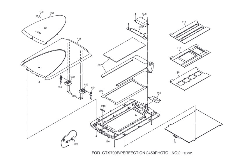
EPSON - Epson Perfection2450Photo Diagram
This parts identification guide for the Epson Perfection 2450 Photo scanner provides three detailed photographic diagrams essential for service and maintenance work. The first diagram shows the scanner with lid open, clearly labeling all major internal and external components—document feeder assembly, paper guides, drive rollers, and mechanical assemblies—so you can see how everything fits together. The second diagram focuses on the scanning glass platen and optical elements, identifying the glass assembly parts and guidance mechanisms you'll encounter during disassembly or component replacement. The third diagram illustrates proper loading and insertion of film strips, slides, and documents, making it straightforward to understand the accessory pathways through the scanner. Every part carries a specific reference code for quick, accurate identification when ordering replacements or performing maintenance. Whether you're a service technician diagnosing a mechanical issue, a maintenance professional planning a routine overhaul, or an experienced user tackling a repair, this parts diagram delivers the visual precision you need to work confidently on the Perfection 2450 Photo scanner.
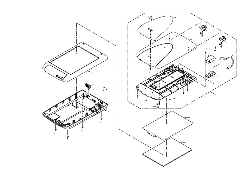
EPSON - Epson Perfection3170Photo Diagram
Detailed technical assembly diagram for the Epson Perfection 3170 Photo scanner (GT-9400UF model). This three-page photographic breakdown provides a systematic visual reference for the scanner's internal structure and mechanical design. The first sheet documents detachable accessories and external components—power cable, AC adapter, control panel, scanning bed assembly, and alignment fixtures. The second sheet presents an exploded view of the main scanner chassis, clearly showing the housing structure, drive mechanism, and all electrical connectors in their proper positions. The third sheet isolates the internal mechanical subsystems: the drive system, positioning guides, optical sensors, and the complete scanning mechanism with individual component callouts. Every part carries a reference number for quick identification, making this diagram invaluable for service technicians performing maintenance, troubleshooting, component replacement, or repair work on the Perfection 3170. Whether you need to locate a specific assembly, understand how the mechanism fits together, or track down a replacement part, this service diagram is an essential technical resource for anyone working on this scanner model.
EPSON - Epson Perfection3200Photo Diagram
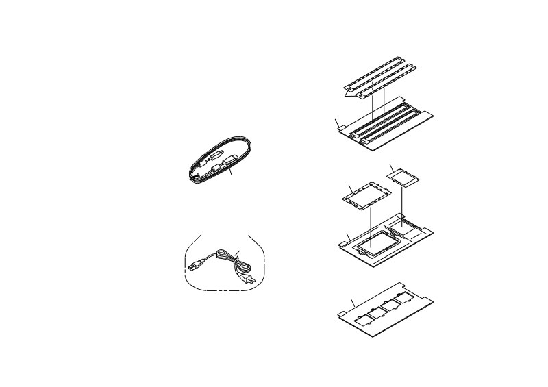
This detailed parts diagram set for the Epson Perfection 3200 Photo scanner provides complete visual reference for assembly, maintenance, and troubleshooting. Organized in four sections, it covers accessories for both 220/230V/240V and 100/120V power configurations, including power cables and positioning brackets. The housing assembly diagrams identify all external and internal components of the GT-9800F/Perfection 3200 with precision numbering (100-240 series). A comprehensive mechanical breakdown shows the arrangement of power supplies, optical assemblies, and mechanical elements across voltage variants (200-610 series). The final section illustrates carton packaging and initial setup, demonstrating how accessories are arranged for delivery. All components are systematically numbered and coded, making this service documentation essential for identifying part locations and relationships during assembly, disassembly, repair, or diagnostic work on this flatbed photo scanner.
EPSON - Epson Perfection4180Photo Diagram
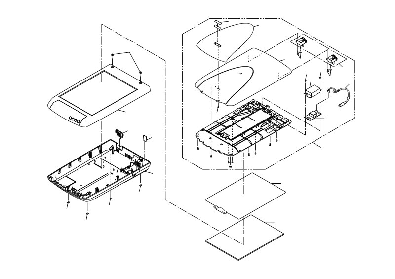
Complete technical schematic documentation for the Epson GT-F600 / Perfection 4180 flatbed photo scanner, presented as three detailed photo diagram series. The first series (Photo No.1 - B170-ACCE-001) covers external accessories and installation components: power cable (400), power adapter (401), control unit (402), base plate (10), intermediate tray (20), positioning frame (30), and transport unit (40). The second series (Photo No.2 - B170-CASE-001) details the main housing assembly structure, including top cover sections (100, 102, 103), side walls, closure elements (113), and internal components as they appear during step-by-step disassembly. The third series (Photo No.3 - B170-MECH-001) provides full mechanical deconstruction, revealing the optical system (500 to 536), drive motors, scanning unit (600), sensors, and electromechanical assemblies (200, 201) critical to scanner operation. Essential reference for service technicians, repair specialists, and support engineers performing maintenance, troubleshooting, and component identification on the GT-F600 / Perfection 4180.
EPSON - Epson Perfection4490Photo Diagram
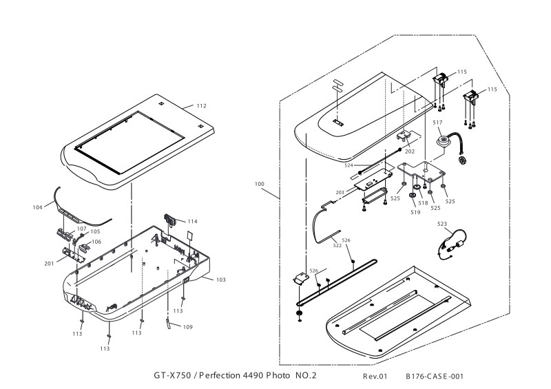
Comprehensive technical diagram guide for the EPSON Perfection 4490 Photo and GT-X750 professional film and photo scanners. This service documentation consists of four detailed illustrated plates that map the complete internal construction and assembly sequence of these imaging devices. The first plate identifies all external accessories and components, including the power cable assembly (400), AC adapter (401), and the optical modules and scanning guides (10, 20, 30, 40, 530) essential to operation. Subsequent plates present full exploded-view cutaway diagrams of the main housing, exposing the CCD sensor assembly, document and film transport mechanisms, positioning fixtures, and the complete optical path. Detailed schematics cover motor assemblies (115), the positioning and drive systems (517-527), guide rails and support structures (523-526), and feed tray architecture. This repair and maintenance resource is essential for technicians working on component replacement, optical alignment, transport system troubleshooting, and understanding the mechanical layout of this professional-grade scanner. The numbered parts and exploded views enable fast component location, accurate disassembly procedures, and informed maintenance decisions.
EPSON - Epson Perfection4870Photo Diagram
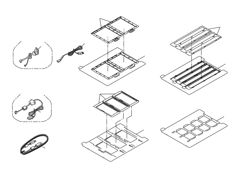
Comprehensive parts diagram and service manual for EPSON GT-X700 and Perfection 4870 Photo and 4870 Pro document scanners. This technical reference presents detailed assembly schematics and component identification across four major sections covering the complete internal architecture of these scanning devices. The manual includes exploded-view diagrams that clearly distinguish electrical connectors for both 100V and 220V AC models, exposure platforms, document frames with systematic part numbering and cross-references, and full chassis and top cover assembly sequences. Separate sections address the optical scanning path and mechanical positioning systems, including sensor calibration and registration mechanisms essential for accurate document capture. Every component is numbered and labeled consistently throughout to enable straightforward identification and parts ordering. Technical illustrations use isometric perspective views that show how each part relates spatially within the final assembly, making component location and replacement procedures clear at a glance. An indispensable workshop reference for maintenance technicians, repair centers, and parts distributors who need accurate component identification for troubleshooting and repair work on these scanner models.
EPSON - Epson Perfection4990Photo Diagram
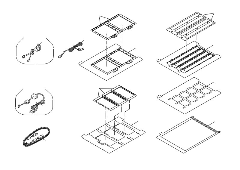
Complete parts identification and assembly diagrams for the EPSON GT-X800 / Perfection 4990 Photo scanner. Organized as four detailed photo sections that map every component and mechanical subsystem of the unit. The first section shows all accessories and power/interface connections, with separate diagrams for 100V and 220V variants including power supply connectors and cable assemblies. Sections two and three break down the external casing, internal frame, optical pathway, and motor drive train. The final section isolates the core mechanical elements—scanning head, stepping motors, drive belts, and carriage guide rails. Each part carries a reference number for quick cross-referencing against the parts list. Indispensable for service technicians and authorized repair centers performing component identification, parts replacement, and mechanical troubleshooting on this flatbed photo scanner.
EPSON - Epson r1800 r2400 Service
Comprehensive service manual for the EPSON Stylus Photo R1800 and R2400 professional color inkjet printers, designed as a complete workshop reference for certified repair technicians. This technical documentation covers systematic maintenance and repair procedures for both printer models across six major sections. The manual begins with product overview and detailed technical specifications, then progresses through electrical and mechanical operating principles to establish a solid foundation for troubleshooting and service work. A dedicated troubleshooting guide cross-references common printer error messages with diagnostic procedures, enabling efficient fault isolation. Step-by-step disassembly and reassembly instructions cover all major components and assemblies, supported by detailed photographic illustrations and technical schematics throughout. The service manual includes Epson-approved adjustment and calibration methods specific to each model, along with preventive maintenance protocols to extend printer lifespan and maintain print quality. The appendix provides connector pin assignments, exploded parts diagrams with comprehensive component listings, and circuit board layouts for reference during service operations. Safety precautions are emphasized, including electrostatic discharge handling requirements for sensitive processor boards, and all procedures mandate the use of manufacturer-approved replacement components only. Revised edition B from 2005 incorporates R2400-specific calibration procedures and operational updates.
EPSON - Epson SP 2100 2200 Service
Comprehensive technical service manual for EPSON Stylus PHOTO 2100 and 2200 color inkjet printers. This professional 258-page workshop manual is designed for certified repair technicians and delivers complete coverage of maintenance, diagnostic, and repair procedures essential for professional photo printer service work. The manual is organized into six core chapters covering product descriptions and specifications, electrical and mechanical operating principles, detailed troubleshooting procedures to resolve common and complex issues, comprehensive disassembly and reassembly instructions with step-by-step guidance, Epson-approved adjustment and calibration methods, and preventive maintenance schedules. The extensive appendix includes connector pin assignments, exploded diagrams with complete parts lists, circuit board component layouts for quick reference during repairs, and detailed electrical schematics showing signal paths and power distribution. Safety precautions and warnings meeting industry standards for professional electronics technicians are integrated throughout the document. Originally released in 2002 with final revisions through August 2002, this service manual serves as an essential reference for all technical service work on these professional photo printer models, whether performing routine maintenance or conducting in-depth component-level repairs.
EPSON - Epson SP r280 Service
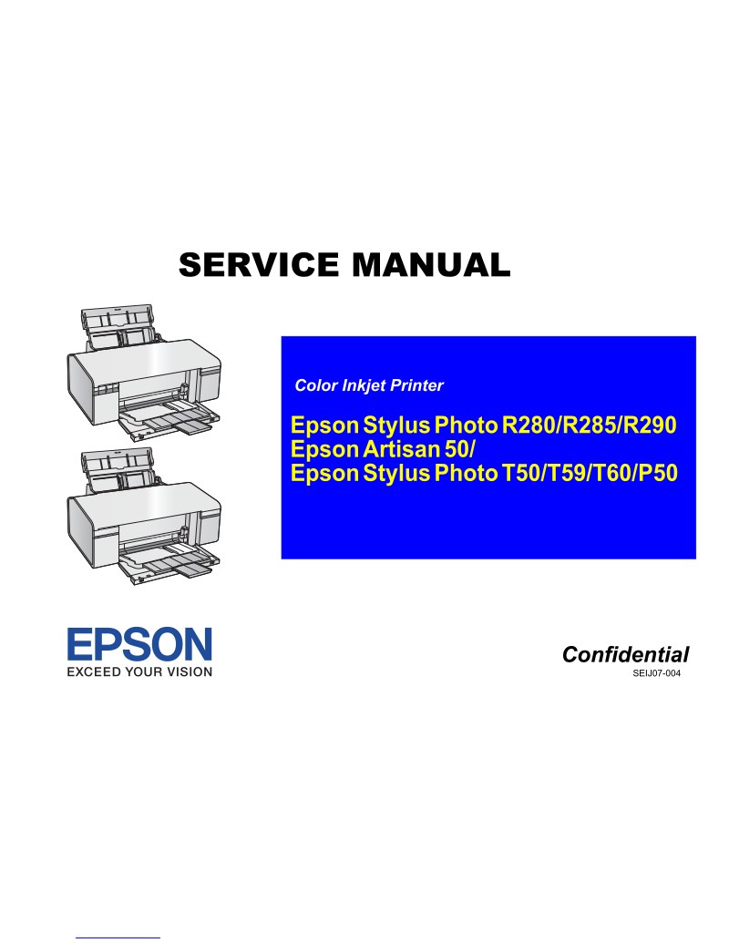
Comprehensive service manual for the Epson Stylus Photo R280, R285, R290, Artisan 50, and Stylus Photo T50, T59, T60, P50 color inkjet printers. This workshop repair manual delivers six detailed chapters covering product specifications and operating principles, electrical and mechanical system design, systematic troubleshooting procedures, complete disassembly and reassembly instructions with step-by-step guidance, Epson-approved adjustment techniques, and preventive maintenance protocols using specified lubricants and adhesives. Includes power-on sequence documentation and printer initialization procedures essential for service technicians. The appendix contains exploded parts diagrams and comprehensive parts lists for all model variants. Designed as a technical reference for authorized service work, component replacement, performance diagnostics, and long-term equipment maintenance.
EPSON - Epson SP10000 Service
Comprehensive service manual for the EPSON Stylus Pro 10000 and 10000CF large-format printers. This technical workshop manual is designed for certified EPSON repair technicians and delivers detailed coverage of maintenance and troubleshooting for these professional-grade printing systems. The documentation is organized into seven chapters: product descriptions and specifications, electrical and mechanical operating principles, systematic troubleshooting procedures, complete disassembly and reassembly workflows, EPSON-approved adjustment methods, and preventive maintenance protocols. The appendix supplies essential technical reference material including connector pin assignments, parts lists with component identification, electronic circuit board schematics and component layouts, exploded diagrams for mechanical assemblies, and complete electrical circuit diagrams. Safety receives detailed treatment throughout, with particular emphasis on the laser system incorporated in the Auto Point Head Optimization feature, including comprehensive warnings and safety procedures. The manual documents proper use of EPSON-approved lubricants and adhesives required for correct maintenance and reassembly. Whether diagnosing electrical faults, performing routine service, or executing major repairs, this repair guide equips technicians with the diagnostic procedures and technical specifications necessary to maintain and restore these professional printing systems to full operating condition.
EPSON - Epson SP1200 Service
Comprehensive service manual for the EPSON Stylus Photo 1200 color inkjet printer. This workshop manual is designed for certified maintenance and repair technicians who need authoritative technical reference material. Coverage includes operating principles that explain the mechanical and electrical fundamentals of the device, detailed troubleshooting procedures to diagnose and resolve common issues, and step-by-step disassembly and reassembly instructions for all major components. The technical specifications outline 1440 x 720 dpi printing capability with 6-color output, an integrated automatic sheet feeder supporting multiple media types, and three interface options—IEEE-1284 parallel, serial, and USB. The adjustment section features an exclusive adjustment program with improved user interface, providing activation procedures and model-specific calibration routines for the Stylus Photo 1200. Extensive appendix materials include detailed exploded diagrams organized in multiple sections, clearly identifying all major components, subassemblies, and printer mechanism parts. Circuit board documentation covers the three primary boards: C259/C264 Main Board, C257 Power Supply Board, and C206 Control Panel Board, with pinouts and functional descriptions. This repair manual serves as an essential technical resource for authorized service centers and qualified technicians performing maintenance and repairs on this printer model. PDF download includes all diagrams and technical data needed for professional servicing.
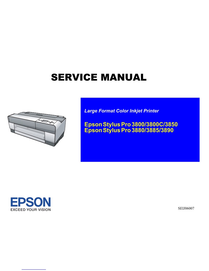
EPSON - Epson SP3800 Service
Complete service manual for the EPSON Stylus Pro SP3800, a professional wide-format photo printer designed for A2+ output (44 cm width). This 306-page technical reference equips authorized service technicians and maintenance professionals with diagnostic procedures, troubleshooting methodologies, and repair instructions needed to identify and resolve technical issues. The manual covers detailed system specifications, internal architecture, and step-by-step component replacement procedures for critical assemblies including the print head, ink cartridge systems, and mechanical subassemblies. Also included are calibration sequences, diagnostic test protocols, configuration parameters, and preventive maintenance schedules. This documentation provides everything required to maintain printer functionality, ensure consistent print quality, and extend equipment service life in professional environments.
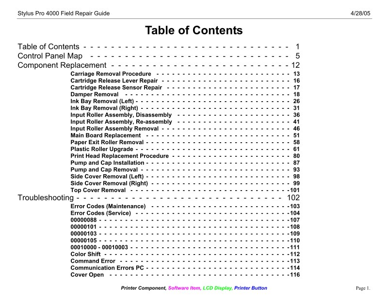
EPSON - Epson SP4000 FieldRepair
Field repair manual for the EPSON Stylus Pro 4000 large-format printer. This 231-page service manual is built for technical support staff and maintenance professionals who need to diagnose and repair this professional photo printer in the field. The manual covers diagnostic procedures, troubleshooting steps, and repair instructions specific to the Stylus Pro 4000. You'll find methodical repair procedures, component references, and preventive maintenance guidance—the kind of practical information that helps you identify what's gone wrong, execute the fix, and get the printer back online. Designed to work as a portable reference for on-site work, this repair guide complements EPSON technical documentation and gives authorized service providers and support centers the detail they need to handle common failures and keep equipment running. Table of Contents: - Stylus Pro 4000 Field Repair Guide - Printer Component, Software Item, LCD Display, Printer Button - Page 1. - Table of Contents - - - - - - - - - - - - - - - - - - - - - - - - - - - - - - 1 - Control Panel Map - - - - - - - - - - - - - - - - - - - - - - - - - - - - - 5 - Component Replacement - - - - - - - - - - - - - - - - - - - - - - - - - - 12 - Carriage Removal Procedure - - - - - - - - - - - - - - - - - - - - - - - - - - 13 - Cartridge Release Lever Repair - - - - - - - - - - - - - - - - - - - - - - - - - 16 - Cartridge Release Sensor Repair - - - - - - - - - - - - - - - - - - - - - - - - 17 - Damper Removal - - - - - - - - - - - - - - - - - - - - - - - - - - - - - - - - 18 - Ink Bay Removal (Left) - - - - - - - - - - - - - - - - - - - - - - - - - - - - - - 26 - Ink Bay Removal (Right) - - - - - - - - - - - - - - - - - - - - - - - - - - - - - 31 - Input Roller Assembly, Disassembly - - - - - - - - - - - - - - - - - - - - - - 36 - Input Roller Assembly, Re-assembly - - - - - - - - - - - - - - - - - - - - - - 41 - Input Roller Assembly Removal - - - - - - - - - - - - - - - - - - - - - - - - - 46 - Main Board Replacement - - - - - - - - - - - - - - - - - - - - - - - - - - - - 51 - Paper Exit Roller Removal - - - - - - - - - - - - - - - - - - - - - - - - - - - - 58 - Plastic Roller Upgrade - - - - - - - - - - - - - - - - - - - - - - - - - - - - - - 61 - Print Head Replacement Procedure - - - - - - - - - - - - - - - - - - - - - - - 80 - Pump and Cap Installation - - - - - - - - - - - - - - - - - - - - - - - - - - - - 87 - Pump and Cap Removal - - - - - - - - - - - - - - - - - - - - - - - - - - - - - 93 - Side Cover Removal (Left) - - - - - - - - - - - - - - - - - - - - - - - - - - - - 98 - Side Cover Removal (Right) - - - - - - - - - - - - - - - - - - - - - - - - - - - 99 - Top Cover Removal - - - - - - - - - - - - - - - - - - - - - - - - - - - - - - -101 - Troubleshooting - - - - - - - - - - - - - - - - - - - - - - - - - - - - - - 102 - Error Codes (Maintenance) - - - - - - - - - - - - - - - - - - - - - - - - - - -103 - Error Codes (Service) - - - - - - - - - - - - - - - - - - - - - - - - - - - - - -104 - Color Shift - - - - - - - - - - - - - - - - - - - - - - - - - - - - - - - - - - - -112 - Command Error - - - - - - - - - - - - - - - - - - - - - - - - - - - - - - - - -113 - Communication Errors PC - - - - - - - - - - - - - - - - - - - - - - - - - - - -114 - Cover Open - - - - - - - - - - - - - - - - - - - - - - - - - - - - - - - - - - -116
EPSON - Epson SP4910 Service
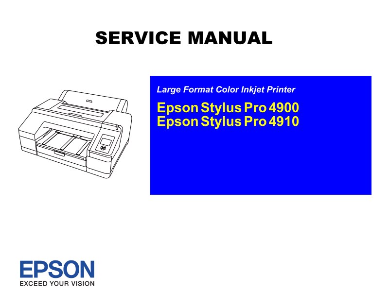
Comprehensive service manual for the EPSON Stylus Pro SP4910 large-format printer, a professional photo printer engineered for commercial photography labs and production environments. This 441-page technical resource serves as an essential workshop manual for maintenance technicians, repair specialists, and service department managers. The document delivers detailed troubleshooting procedures, repair methodologies, and diagnostic workflows tailored specifically to the SP4910 model. Coverage includes the printer's mechanical and electronic architecture, critical internal subsystems, preventive maintenance schedules, and step-by-step repair procedures for common issues. As a service manual designed for technical professionals, it provides the structured information needed to identify fault conditions, isolate root causes, and implement targeted corrective measures. The guide enables technicians to restore the printer to full operational capability and sustain peak performance in demanding professional photography and print production settings.
EPSON - Epson SP5000 Service
Complete service manual for the EPSON Stylus Pro SP5000 large-format printer. This 235-page technical reference provides everything needed to diagnose, maintain, and repair this professional-grade color printer used in photography labs and print production environments. The manual includes detailed disassembly and reassembly procedures, complete technical specifications, internal mechanism operation guides, preventive and corrective maintenance protocols, and comprehensive troubleshooting steps. Component diagrams, assembly instructions, error code reference, calibration procedures, and specific cleaning protocols for ink delivery and paper feed systems are all covered. Designed for authorized service technicians, repair centers, and field maintenance professionals, this manual delivers the precise technical information required for rapid diagnostics and efficient repairs, helping minimize downtime and extend equipment lifespan.
EPSON - Epson SP7400 Service
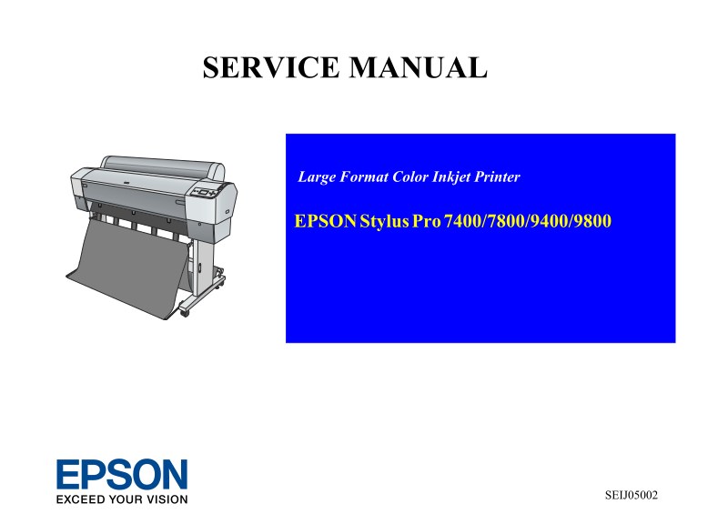
Comprehensive service manual for the EPSON Stylus Pro 7400, a professional wide-format inkjet printer built for high-end photographic and graphic production. This 428-page technical reference is an essential workshop manual for field service technicians, authorized repair centers, and maintenance departments working on this model. The manual covers everything required to diagnose, repair, and maintain the equipment reliably. You'll find detailed disassembly and reassembly procedures for all major components, complete hardware specifications, systematic troubleshooting protocols, and preventive maintenance schedules that keep the printer operating at full capacity. Specific sections address the paper feed mechanism, ink delivery and circulation systems, sensor arrays, and control circuit architecture—all documented with the precision needed for complex repairs in demanding commercial environments. Whether performing routine maintenance or addressing equipment failures, this service manual provides the technical data and procedural guidance necessary to restore and sustain professional-level performance.
EPSON - Epson SP7600 Service
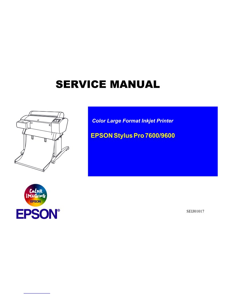
Complete service manual for the EPSON Stylus Pro 7600 and 9600 large-format color inkjet printers. This comprehensive technical reference is designed for EPSON-certified repair technicians and covers all maintenance and repair procedures for these professional wide-format printing systems. The manual spans six chapters addressing product descriptions and technical specifications, electrical and mechanical operating principles, step-by-step troubleshooting procedures, detailed disassembly and reassembly instructions, EPSON-approved adjustment methods, and preventive maintenance schedules with approved lubricants and adhesives. The appendix includes connector pin assignments, printed circuit board schematics and component layouts, exploded diagrams, and comprehensive parts lists for identifying replacement components. Safety guidelines throughout highlight critical DANGER and WARNING procedures that technicians must follow during maintenance and repair work, using clear symbols and notations to mark essential operating practices and precautions. Service professionals will find this workshop manual enables accurate diagnosis, component-level repair, and preventive maintenance on these wide-format inkjet systems. First edition, May 2002, reference SEIJ01017.
EPSON - Epson SP7700 Service
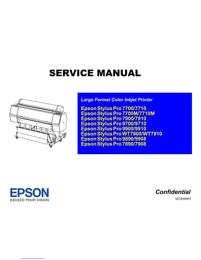
Comprehensive service manual for the EPSON Stylus Pro 7700, a professional large-format inkjet printer engineered for high-quality photographic output. This 519-page technical reference covers diagnostic procedures, troubleshooting methods, and maintenance operations essential for reliable equipment operation. The manual includes detailed service procedures, component replacement instructions, and technical specifications for identifying and resolving equipment failures. Technicians will find step-by-step guidance on routine maintenance, parts sourcing, and systematic fault isolation. Designed for authorized service centers and qualified repair professionals, this workshop manual provides the in-depth technical knowledge required to keep the Stylus Pro 7700 operating at peak performance.
EPSON - Epson V500Photo Diagram
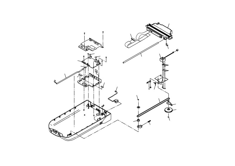
Comprehensive technical parts diagram for the Epson GT-X770 and Perfection V500 photo scanners, featuring detailed exploded-view illustrations with numbered service components across three separate diagrams. Photo No.1 illustrates all external accessories and connection points, including the power cable (400), power adapter (401), and document positioning holder elements (10, 20, 30, 40). Photo No.2 breaks down the complete case assembly structure, covering both top and bottom panels (100-115), fastening hardware, internal chassis framework, and the glass platen retention system. Photo No.3 reveals the full internal mechanical layout, including the optical scanning head with CIS sensor array (500-516), stepper motors and drive gears (501-514), and the precision linear guide rails (526-532) that control sensor movement across the platen. Every component carries a clear reference number for straightforward parts identification and ordering. This parts diagram serves maintenance technicians, professional repair shops, and technical support teams who need accurate component location and nomenclature for troubleshooting, preventive maintenance, and parts replacement on either scanner model.
EPSON - Epson V550Photo Diagram
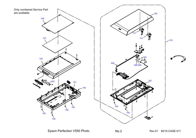
Complete technical parts diagram for the Epson Perfection V550 Photo scanner, presented as three detailed exploded-view sheets serving as an essential service reference for component identification and parts ordering. Sheet B210-ACCE-011 illustrates scanner accessories with numbered elements 10, 20, and 30, showing perspective views of tray and adapter assemblies. Sheet B210-CASE-011 provides a full exploded breakdown of the external housing, identifying cover panels (106, 107), hood components (109, 110), main scanning bed assembly (100, 101, 102, 103), and fastening hardware including screws and springs (105, 506). Sheet B210-MECH-011 exposes the internal mechanical assembly, clearly labeling the optical system (500, 501, 502, 507), movement rails (506), motor assembly (200, 206), and operational mechanism components. Each part carries a precise reference number, making this diagram invaluable for ordering genuine Epson replacement parts, performing maintenance, or diagnosing mechanical issues. Whether conducting routine maintenance, troubleshooting performance problems, or rebuilding scanner assemblies, these workshop diagrams provide the visual reference needed to identify exact components and their relationships within the scanner structure.
EPSON - Epson V600Photo Diagram
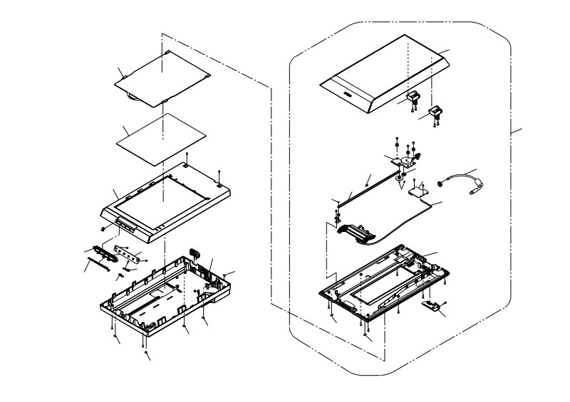
This technical documentation provides detailed component diagrams and parts location illustrations for the Epson GT-X820 and Epson Perfection V600 Photo scanners. Organized across three pages of numbered technical drawings, it comprehensively catalogs all available service parts and their assembly positions. Page 1 presents external accessories and auxiliary components including the power cord (400), external power adapter (401), connection cables (402), document feeding tray (10), transport belts (20), and sensor modules (30) essential for document scanning operations. Page 2 details the complete scanner assembly with primary structural and functional components: the upper cover (106, 107), main chassis (100), closure mechanisms (108, 109), touch switches (110), and the full internal architecture of the scanning and drive mechanisms including components numbered in the 500-515 series. Page 3 provides an exploded view of internal mechanisms including the optical scanning system (500-507), drive motors (501), sensor assemblies (503), guide rails (505), transmission elements (502, 504, 506, 508, 509), and optical components critical to achieving high-quality scan output. Each part is identified with a specific reference number, facilitating accurate component identification for parts ordering and equipment repair procedures. This parts diagram serves as an essential workshop reference for authorized service technicians, repair centers, and maintenance personnel tasked with scanner troubleshooting and component replacement.
EPSON - Epson V750 V700 Diagram
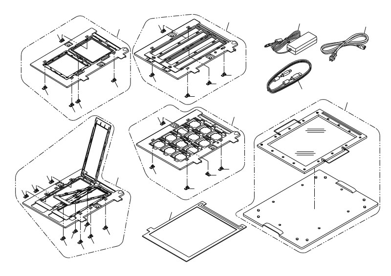
Complete technical parts diagram and assembly reference for EPSON Perfection V750-M PRO, V750 PRO, GT-X900, and Perfection V700 PHOTO document scanners. This service manual delivers detailed mechanical and optical architecture documentation essential for understanding the internal construction of these professional-grade scanning devices. The diagram manual organizes component information across four core sections: accessory components and connectors including power supplies and network interface cables, external housing and structural assembly covering covers, hinges, and support brackets, the complete internal optical and mechanical architecture with document transport mechanisms and precision positioning assemblies, and the transmission systems with motors, control levers, and guidance components. Each isometric diagram includes precise component reference numbering for accurate part identification. Exploded views clarify the spatial relationship between assemblies and indicate attachment points throughout the device. Maintenance technicians, authorized service centers, and repair professionals will find this parts diagram invaluable for troubleshooting mechanical faults, performing preventive maintenance, planning component replacements, and understanding the precise mechanical configuration of these scanning systems.
EPSON - Epson V800 V850 Diagram
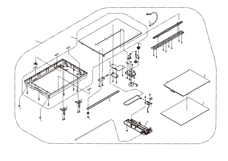
Comprehensive parts diagram and exploded-view catalog for Epson Perfection V850 Pro and GT-X980 professional scanners. This service parts list uses detailed technical drawings to identify every serviceable component, each assigned a unique reference number for direct ordering through Epson service channels. The documentation covers mechanical and optical assemblies including the scanner housing, glass platens, scan head mechanisms, and imaging sensors, plus the drive systems that power them—motors, timing belts, and feed rollers. Internal electronics sections detail circuit boards, connectors, and wiring harnesses, while accessories coverage includes scanning platforms and adapter modules for various document and photo configurations. Three-dimensional exploded views show spatial relationships between parts, making component identification straightforward during repair or preventive maintenance work. Multiple part-numbering sequences throughout reflect different regional variants and configuration options for these high-resolution scanning systems. An essential workshop reference for authorized service technicians, independent repair professionals, and maintenance departments sourcing replacement parts or diagnosing wear items.